Safety#
Overview#
This paper introduces important information such as safety matters and risk assessment that should be paid attention to when installing, using and maintaining the robot and its components, which must be read and understood by the user before the robot is powered on for the first time.
Before performing any operation, ensure that you have read all the operation instructions provided with the device, especially the dangers, warnings, and precautions that may endanger the safety of the human body and the device to minimize the chance of accidents. If this document is different from the document delivered with the device, the document delivered with the device shall prevail.
The personnel responsible for the installation and maintenance of the equipment must be trained professionals who have mastered the proper operation methods and all safety precautions. Only trained and qualified personnel are allowed to install and maintain devices.
Effective Scope and Responsibility Statement#
This information does not include how to design, install and operate a complete robot system, nor does it include all peripherals that can affect the safety of the entire system. In order to protect human safety, the system must be well designed and must be installed in accordance with the safety requirements specified in the standards and regulations of the country in which the robot is installed.
The robot integrator shall be responsible for ensuring that the robot system complies with the applicable safety laws and regulations of the country or region in which it is located, and that the necessary safety equipment to protect the operator of the robot system is properly designed and installed.
The details include but are not limited to the following:
Ensure that robot systems meet all basic requirements;
Perform a risk assessment of the complete system;
Ensure the design and installation of the entire system is accurate;
Make appropriate safety Settings in the software and ensure that they are not modified by users;
Develop detailed operating instructions;
Issue a declaration of conformity;
Collect all information in technical documents;
Label the installed robot system with the integrator’s logo and contact information.
Siasun Co., Ltd. is committed to providing reliable safety information and shall not be liable unless there is intentional or gross negligence on the part of SiASun Co., Ltd. in providing reliable safety information. To be clear, even if everything is done in accordance with safe operation, there is no guarantee that the robot system will not cause personal and property damage to the user.
Zhongke Siasun Co., Ltd. will not be liable for user losses caused by the following reasons:
Force majeure events (e.g. natural disasters, fires, wars, etc.);
Natural damage or wear of the robot system;
The site operating environment (for example, voltage, temperature, humidity, etc.) or external factors (for example, external interference, etc.) cannot meet the environmental requirements for normal operation that have been prompted;
The robot system is not installed correctly (including not re-installed correctly after relocation);
Due to intentional or negligent use by the User or a third party, improper use (including the user’s failure to use in accordance with this User manual and/or other requirements of Siasun Limited) or sabotage.
Unless otherwise agreed, the company shall not be liable for indirect, special or incidental losses caused by the use of the robot system, including but not limited to loss of revenue, loss of actual or expected earnings, loss of business, loss of opportunity, loss of goodwill, loss of reputation, loss of data, damage or disclosure.
Risk Assessment#
Risk assessment is one of the most important tasks that an integrator must perform. The robot itself is a partially completed machine, and the safety of the robot installation depends on how the robot is integrated (e.g. tools, obstacles, and other machinery).
Integrators are advised to perform risk assessments in accordance with standards ISO12100 (GB 15706) and ISO10218-2 (GB 11291.2). Alternatively, the technical specification ISO/TS 15066 (GB/ T 36008) can be selected as additional guidance. Integrators performing risk assessments should consider all work procedures throughout the robot’s application life, including but not limited to:
Teach robots when developing robot installations;
Fault diagnosis and maintenance;
Normal operation of robot installation.
The risk assessment must be carried out before the robot is powered on for the first time. Part of the risk assessment performed by the integrator is to identify the correct safety configuration Settings and determine whether additional emergency stop buttons and other protective measures are required.
The following identifies the major risks that integrators must consider. Please note that there may be other significant hazards associated with a particular robot device.
The finger is sandwiched between joint 4 and joint 5 of the robot.
Sharp edges and sharp points on tools or tool connectors puncture the skin.
Sharp edges and sharp points on obstacles near the robot’s trajectory puncture the skin.
Sprains or fractures due to impact between the robot payload and a solid surface.
Consequences of loose bolts used to hold the robot or tool in place.
Items fall off the tool, for example due to improper clamping or power failure.
Operation errors due to different emergency stop buttons on different machines.
If the robot is installed in a non-collaborative robot application where the risk cannot be adequately eliminated using its internal safety features, such as the use of hazardous tools, the system integrator must install additional protection based on the risk assessment (for example, using protection that can protect the integrator during installation and programming). Due to the failure to install protective devices caused by the loss, Siasun Co., Ltd. will not be responsible for this.
Safety Operation#
Emergency Shutdown#
Emergency shutdown is a condition that takes precedence over all other robot control operations and will result in all controlled hazardous stops, eliminate motor power from the robot drive, remain active until reset, and can only be restored by manual operation.
The emergency stop state means that the power system is disconnected and the robot cannot move. The user must perform the restore step, that is, reset the emergency stop button and press the “Power on” button on the teach pendant to resume normal operation. Emergency downtime cannot be used as a risk reduction measure, but can be used as a secondary protection device.
Emergency shutdowns should not be used for normal program stops, as this may cause additional unnecessary wear and tear on the robot.
Safety Related Functions#
Safety Function Introduction#
The GCR series robots are equipped with a variety of built-in safety features as well as safety I/O, digital and analog control signals for emergency electrical interfaces for connecting other robots and additional protective devices.
Safety Stop Categories#
Depending on the situation, the robot can initiate three types of Safety Stop defined in accordance with IEC60204-1. These categories are defined in the following table.
Safety Stop Category |
Description |
|---|---|
0(SS0) |
Cut off the robot power immediately |
1(SS1) |
Immediately reduce the speed of each joint to 0 with the fastest acceleration, spring up the lock gate after the joint is stationary, and cut off the robot power supply |
2(SS2) |
The robot is slowed down to a standstill while maintain ing the trajectory. After the standstill, all joints remain in the enabled state, and the brake is not moved. |
Switching between Safety Stop categories:
When a Type 1 stop is performed, a timer is triggered at the same time. If the robot still exceeds the set safe speed after 500ms, it will switch to Class 0 Safety Stop.
Safety Features#
The SIASUN collaborative robot safety functions listed in the table below are located in the robot and are intended to control the robot system, i.e. the robot and the connected tools/end-effectors. Robot safety functions are used to reduce the risks to robot systems as determined by risk assessment.
Safety function |
Description |
|---|---|
Emergency stop (ES) |
Executing SS1 |
Protective stop |
Executing SS2 |
Safe Operating Stop (SOS) |
After ss2 is executed, SOS monitoring will be triggered to monitor the current robot position deviation,and SS0 will be triggered if it is violated |
Joint Safe limited position (SLP) |
According to the threshold setting, SS2 is triggered when the joint position reaches the threshold. If the joint limit is triggered, ss0 is directly triggered |
Joint Safe limited speed (SLS) |
According to the threshold setting, SS2 is triggered when the joint speed reaches the threshold. If the joint speed imit is triggered, ss0 is directly triggered |
TCP position limit |
A safety plane can be set to limit the working area of the robot, which is set according to the threshold value When the threshold value is reached,SS2 is triggered If the safety plane is triggered, the safetycontroller directly triggers ss0. A maximum of six safety planes and three TCP coordinate systems are allowed |
Tcp speed limit |
According to the threshold setting, SS2 is triggered when he threshold is reached. If the Tcp speed limit is triggered,the safety controller directly triggers ss0 |
elbow pos limit |
According to the threshold setting, SS2 is triggered When the threshold is reached. If the elbow position restriction is triggered, the safety controller directly triggers ss0 |
elbow speed limit |
According to the threshold setting, SS2 is triggered when the threshold is reached. If the elbow speed limit is triggered, the safety controller directly triggers ss0 |
joint force limit |
According to the threshold setting, SS2 is triggered when the threshold is reached. If the joint torque limit is triggered, the safety controller directly triggers ss0 |
tcp force limit |
According to the threshold setting, SS2 is triggered when the threshold is reached. If the end force limit is triggered, the safety controller directly triggers ss0 |
elbow force limit |
According to the threshold setting, SS2 is triggered when the threshold is reached. If the elbow force limit is triggered, the safety controller directly triggers ss0 |
power limit |
According to the threshold setting, SS2 is triggered when the threshold is reached. If the power limit is triggered, the safety controller directly triggers ss0 |
mode switch input |
If the physical input is disabled, you can switch through the UI. But not both at the same time. SS2 is triggered when the mode is changed. If the script is paused, the script can continue to run. |
enable device input |
You can choose whether to enable this input. This input is valid only in manual mode and not in automatic mode. Violation triggers SS2. |
protective stop input |
If this parameter is valid in all modes,SS2 is triggered. If the safety protection reset input is not activated, it automatically resets after the signal disappears. Otherwise, the reset input needs to be triggered before the reset can be performed. |
protective stop reset input |
You can choose whether to reset the signal input. If the safety protection reset is activated, when the triggering safety protection stops and the triggering signal disappears,the channel signal input is required before the movement can continue. The rising edge is val id,and the high level needs to be maintained for 500ms. |
automatic protective stop input |
This parameter is valid only in automatic mode. SS2 is triggered. After the signal disappears, the safe mode returns to normal |
automatic protective stop reset input |
Similar to the protective stop reset input, it is only valid for the。 protective stop triggered by the automatic protective stop input. |
system emergency stop output |
This signal is generated only when the system is triggered by an emergency stop |
protective stop output |
protective stop output. This signal is output when the protective stop input is triggered |
automatic protective stop output |
Automatic mode protection stops output. This signal will be output only when the protection stops in automatic mode. |
reduce mode |
The reduced mode is triggered and parameters related to the reduced mode are used. |
reduce mode output |
The signal can be output globally. |
recovery mode |
When the joint limit or tcp limit is exceeded, you need to restart to enter the recovery mode. recovery mode limits joint speed to no more than /s. 30deg/s and end speed to no more than 250mm |
Safety IO Interfaces#
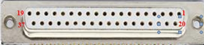
The safety IO interface is an external SCram and safety input and output interface provided by the control cabinet, including 1 SCram signal input (passive signal), 1 SCram feedback output (active signal), 1 protective stop input (passive signal), 2 configurable safety input (passive signal), and 2 configurable safety output (active signal). Among them, the scram signal input, protective stop input and configurable safety input are valid at high levels, and the effective level is 11V-30VDC; In addition, when the configurable safety output and scram feedback output are used, the relay needs to be connected for switching.
Configurable safety input The safety input can be: protected against reset input, protected against Stop input in automatic mode, protected against reset input in automatic mode, and protected against input in reduce mode. Configurable safety output can be configured to stop output in defense mode, Stop output in automatic defense mode, and output in reduce mode. The interface definition is as follows:
Safety I/O interface definition
ID |
Signal definition |
ID |
Signal definition |
|---|---|---|---|
1 |
EI1+ (SCram signal input 1+) |
2 |
EI1- (SCram signal input 1-) |
3 |
EI2+ (SCram input 2+) |
4 |
EI2- (SCram signal input 2-) |
5 |
PS1+ (Protective stop input 1+) |
6 |
PS1- (Protective stop input 1-) |
7 |
PS2+ (Protective stop input 2+) |
8 |
PS2- (Protective stop input 2-) |
9 |
CI1_1+ Configurable safety input 1 (1+)] |
10 |
CI1_1- [Configurable safety input 1 (1-)] |
11 |
CI1_2+ [Configurable safety input 1 (2+)] |
12 |
CI1_2- [Configurable safety input 1 (2-)] |
13 |
CI2_1+ [Configurable safety input 2 (1+)] |
14 |
CI2_1- [Configurable safetyinput 2 (1-)] |
15 |
CI2_2+ Configurable safety input 2 (2+)] |
16 |
CI2_2- [Configurable safety input 2 (2-)]] |
17 |
Reserved |
18 |
Reserved |
19 |
Reserved |
20 |
Reserved |
21-23 |
Reserved |
24-25 |
Reserved |
26 |
CO2_2-[Configurable safety output 2 (2-)] |
27 |
CO2_2+[Configurable safety output 2 (2+)] |
28 |
CO2_1-[Configurable safety output 2 (1-)] |
29 |
CO2_1+[Configurable safety output 2 (1+)] |
30 |
CO1_2-[Configurable safety output 1 (2-)] |
31 |
CO1_2+[Configurable safety output 1 (2+)] |
32 |
CO1_1-[Configurable safety output 1 (1-)] |
33 |
CO1_1+[Configurable safety output 1 (1+)] |
34 |
EO1-(SCram feedback output 1-) |
35 |
EO1+(SCram feedback output 1+) |
36 |
EO2-(SCram feedback output 2-) |
37 |
EO2+(SCram feedback output 2+) |
Clamp Injury and Collision Risk#
There are still blind spots in the collision detection function during the actual operation of the robot, and users must pay attention to the risk of collision detection failure or clamp injury under special working conditions. Three typical working conditions are described below.
Working condition 1: When the end position of the robot is more than 1000mm away from the center of the robot base, if the robot moves in the direction of the red arrow as shown in FIG. 2.6.1 and FIG. 2.6.2, the robot is less sensitive to external forces in the direction of movement, and is more prone to the risk of clamping injury. When the robot moves in the direction of the green arrow as shown in FIG. 2.6.1 and FIG. 2.6.2, if the robot collides with the external environment, it will be sensitive to the external force caused by the collision.
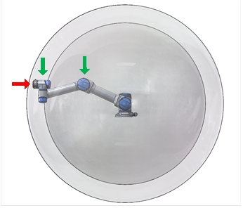
FIG. 2.6.1 Front view of robot under working condition
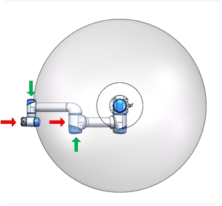
FIG. 2.6.2 Top view of robot under working condition
Working condition 2: With the Z direction of the robot base as the center and the radius of about 350mm, if the contact point is within this range and the direction of the contact force is perpendicular to the plane where the connecting rod of joint 2 and joint 3 is located, the collision detection function is difficult to detect the collision between the robot and the outside world. The red arrows in Figure 2.6.3 and Figure 2.6.4 are shown; At this time, if the direction of the contact force between the robot and the outside world is more consistent with the direction of the base mark Z, the robot is more sensitive to the external force generated by the collision, as shown by the green arrow in Figure 2.6.3.
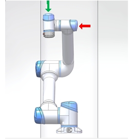
Figure 2.6.3 Front view of working condition 2
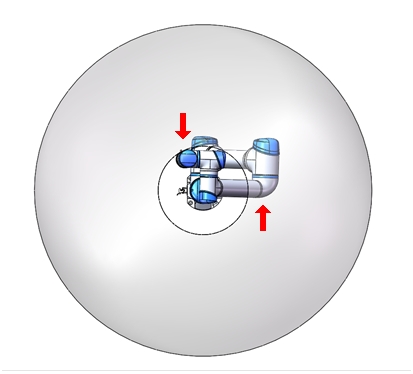
FIG. 2.6.4 Top view of working condition 2
Working condition 3: No matter what pose and motion state the robot is in, when the robot collids with the outside world, if the collision point is centered on the origin of the robot’s base position and the radius is about 350mm, it is difficult for the robot to detect this kind of collision, and the danger of nip injury is more likely to occur, as shown by the red arrow in FIG. 2.6.5 and FIG. 2.6.6. When the collision point is outside the range and does not meet the collision detection blind zone conditions described in working conditions 1 and 2, the robot is easier to detect the collision with the outside world, as shown by the green arrow in Figure 2.6.5 and Figure 2.6.6.
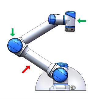
FIG. 2.6.5 Three-side view of working conditions
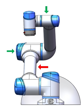
Figure 2.6.6 Three positive view of working conditions
For all the above described working conditions, if the robot moves in a direction that is not sensitive to external collision detection, the operating speed should be reduced as much as possible, taking into account the limited needs of the robot’s cooperation with the outside world.
When the nip accident unfortunately occurs, you can use the manual release brake function to reduce the loss caused by the accident.
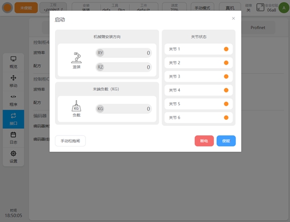
When the robot is powered on but not enabled, you can start the “Manual release lock function” at the lower left corner of the interface. After clicking the “manual release brake” button, the interface will switch as shown in the picture below:
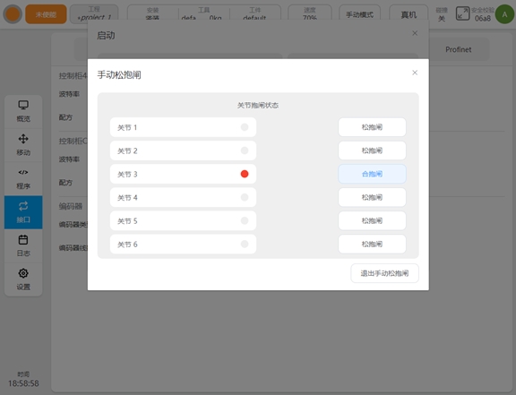
Click the “release lock” button to release the lock of the corresponding joint and allow the joint to be driven without power. The red indicator on the left of the interface indicates the lock status. Click “close lock gate” to re-close the lock gate of the corresponding joint.
Robot Singularity OverSpeed Risk#
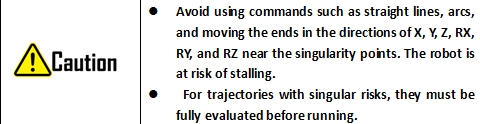
The robot will automatically slow down when performing motion planning (straight line, arc, etc., excluding joint motion) near the singularity, and should avoid the singularity or pass the singularity with joint motion when teaching. There are shoulder singular points, elbow singular points and wrist singular points for GCR series configuration.
Shoulder Singularity#
When the center of the wrist joint O6 is located on the axis J1 of a joint, the shoulder singularity is caused at this time, resulting in no solution of the 1 joint. A strange effect is also experienced when O6 is located very close to J1, where moving the end may cause joint 1 to overdrive. Refer to the figure below for a singular pose near the pose.
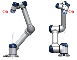
Figure 2.7.1 Shoulder singularity reference pose
Elbow Singularity#
When the two, three and four joint axes J2, J3 and J4 are coplanar, there is no solution to the two joint. Simply, when joint 3 is in the near singular pose near 0 degrees, moving the end may cause joint 2, joint 3, and joint 4 to overdrive. Refer to the figure below for the singular pose near the elbow:
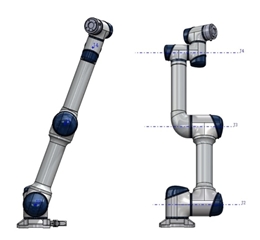
Figure 2.7.2 Elbow singularity reference pose
Wrist Singularity#
When joint 5 is 0 degrees, there is no solution to joint 6, resulting in wrist singularity. When the 5 joint is close to 0 degree, it is a strange posture near the wrist, and moving the end may cause the 4 joints, 5 joints and 6 joints to overspeed. Refer to the following figure:
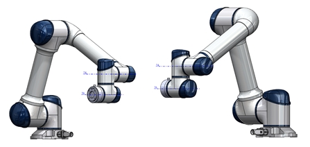
Figure 2.7.3 Wrist singularity reference pose
When the robot runs to or near the above singular points, the planned motion based on Cartesian coordinates cannot be inversely solved to the joint motion of each axis, and the motion planning cannot be carried out correctly. The node motion motion or movej motion command can be adopted.