Palletizing package Settings#
Palletizing process package setup, including engineering setup, BoxPallet module and script optimization.
Project setup: Create a palletizing executive
BoxPallet module: Set pallet scene related parameter definition
Script optimization: Improve the program functions and optimize the path planning of the robot
Project Settings#
1、 “Tool Settings” interface, as shown in Figure 9.
Click the “Settings” button
Select “Tool Settings”
Click the “Add” button
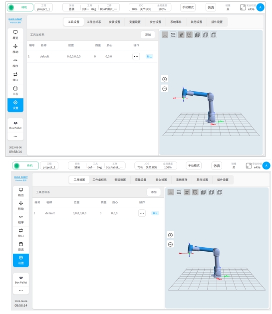
Figure 9
2、Install the tool, as shown in Figure 10.
The Z axis of the tool coordinate system is perpendicular to the plane where the suction cup is located, and the direction is the same as the opening of the suction cup
The plane formed by the X and Y axes of the tool coordinate system coincides with the surface of the suction box
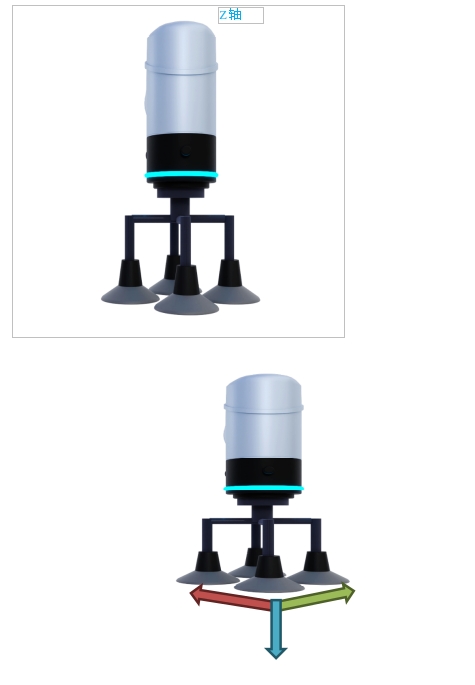
Figure 10
3、 Set coordinate system parameters, as shown in Figure 11.
① : Enter the name of the coordinate system
② : Input six degrees of freedom bias
③ : Input tool quality
Click the “OK” button
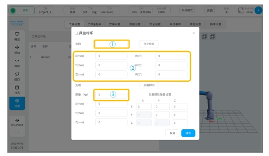
Figure 11
4、 Activate the tool coordinate system, as shown in Figure 12.
Select the generated tool coordinate system
Click “Set as Current”
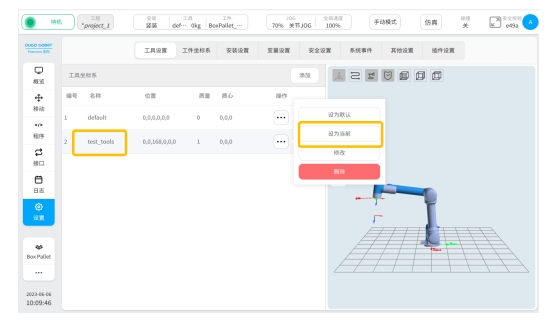
FIG. 12
5、 Click the created project and click “Enter Program”.
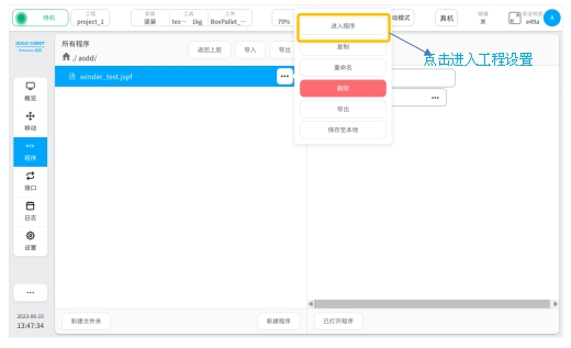
FIG. 13
6、 Add BoxPallet module.
Click the BoxPallet module on the “Instructions” page and drag it to the appropriate location in the programming area
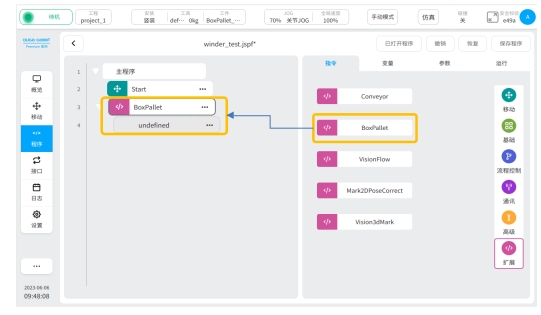
FIG. 14
BoxPallet module#
The BoxPallet module defines a complex solution for palletizing application scenarios in the palletizing process package. This function can make it more convenient for users to define and set parameters.
BoxPallet module has five configuration function interfaces, which are described as follows:
Feeding point configuration: Set parameters related to feeding point
Box configuration: Set box dimensions, quality and other related parameters
Pallet configuration: Set pallet-related parameters for the palletizing box
Stack configuration: Set the number of stack layers and stack layout
Script configuration: Set waypoints and other functions in the palletizing process
module common configuration interface#
1、 Enter the parameter configuration interface of BoxPallet module, as shown in Figure 15.
Click the “Programs” button
Select the module BoxPallet
Position (1) in the figure: Click to change the module name; Position (2) in the figure: click this area and enter the module comment
Select the “Parameter” card, click “Open Configuration Tool” and press

FIG. 15
loading point configuration#
1、Enter the loading point configuration interface, as shown in Figure 16.

Figure 16
2、 teach the material spot.
Click the teaching point button and move the end of robot above the top material point box by operating the teach pendant
As shown in Figure 17, slowly move the end of robot so that the suction cup is fully attached to the housing surface
Ensure that the surface of the suction cup is parallel to the surface of the container
Ensure that the Z-axis of the tool coordinate system is perpendicular to and downward from the plane where the suction cup is located
Ensure that the position and direction of each box at the feeding point are consistent
Click the “Record current position” button to jump to the loading point configuration interface
As shown in Figure 18, the font of “Feed point” appears green, click the “Next” button

Figure 17
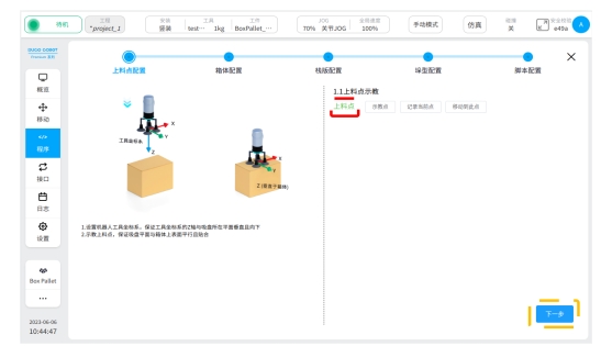
Figure 18
container configuration#
1、 Select the origin of the pallet.
Under the overhead Angle, select any corner of the pallet as the origin of the pallet coordinate system
As shown in Figure 19, the lower right corner of the pallet is used as the origin point
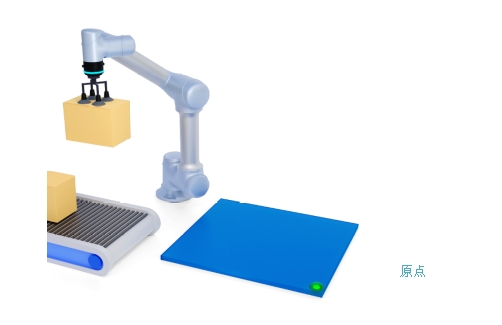
Figure 19
2、 Determine the pallet coordinate system.
Adjust the user’s field of view as shown in Figure 20 so that the pallet origin is at the top left of the field of view
In this field of view, down the origin is the positive direction of the X axis of the pallet coordinate system
In this field of view, the right direction along the origin is the positive Y-axis of the pallet coordinate system
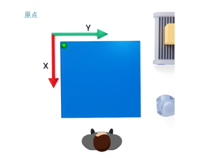
FIG. 20
3、 Set box parameters.
Select any side of the box as the “front”. As shown in Figure 21, “Front” has been selected
As shown in Figure 22, the operating robot will fit the “front” of the box with the upper edge of the pallet, the side with the left edge of the pallet, and the bottom with the pallet
Set the box parameters in Figure 23, where L1(X direction), L2(Y direction)
Click the “Next” button
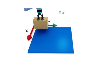
Figure 21
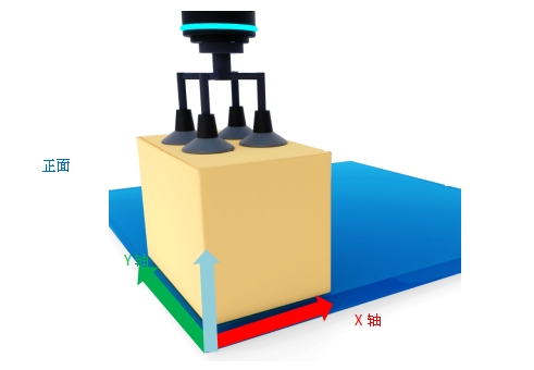
Figure 22
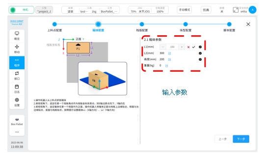
FIG. 23
pallet configuration#
1、Enter the “Pallet Configuration” interface, as shown in Figure 24, and fill in the pallet parameters.
Refer to the “first point” diagram in the figure, pallet side length D1 is the direction of pallet X
The pallet side length D2 is in the Y direction of the pallet

FIG. 24
2、Pallet calibration.
Teach in the order of P1 to P4
Teach P1 point (as shown in the “first point” in Figure 24)
The box position shown in the previous step (box configuration) is denoted as P1 point
Teaching point P2 (as shown in the “second point” in Figure 25)
The robot will translate the box forward along the X axis at any distance (more than half of the side length of the pallet), place the box on the pallet, and confirm that the edge and bottom of the box are fitted. Record it as point P2
Teach P3 point (the “third point” in Figure 25)
Operate the robot to return to point P1, move forward along the Y axis for any distance (more than half of the pallet side length), and place the box on the pallet, similarly referred to as point P3
Teach P4 points (as shown in the “fourth point” in Figure 25)
Operate the robot back to P1 point, turn the box “front” to the bottom (180° in the top view), the same as P4 point
Complete the 4 teaching points and click the “Next” button

FIG. 25
Stack configuration#
1、 Set stack type parameters, as shown in Figure 26.
① Location: Choose A stack type
② Position: Set the boundary reference and enter the actual value in the margin
When stacking on the pallet, if there is a requirement for the spacing between the box and the pallet, please turn on this function, if there is no requirement, you can turn off this function
③ Position: Set the number of layers (palletizing height)
Layer 1 is the lowest layer on the pallet
As the number of layers increases, so does the number of layers
Each layer can be set up A stack or B stack

Figure 26
2、 Place the stack type, as shown in Figure 27.
① Position: Click the box button in any direction (it will be highlighted)
The arrow direction of the container in the figure is consistent with the definition of “front” in the container configuration
② Position: the pallet placement area is shown in the figure (when using the boundary reference, the placement area is in the area surrounded by the boundary reference line)
Place the box into the pallet placement area
Close to the pallet boundary or reference line, click to place, the box will automatically adsorb the border
If a box is placed on the pallet, click close to the box, and the newly placed box will be automatically adsorbed and attached to the existing box
To retype the stack, click the “Empty pallet” button

Figure 27
3、 Adjust the box, as shown in Figure 28.
Click on the box you want to adjust, and three ICONS appear
icon

: Using this icon, rotate the case clockwise (90° per click)
icon

: Use this icon to delete the currently selected box
icon

: Use this icon to confirm the direction and position of the current container
Click on the box to move the box (in the layout area) by dragging and dropping, and click on the icon once it is in place


Figure 28
4、 Switch the stack type, as shown in Figure 29.
As shown in the picture, set the B-stack type
The same way to complete the B-stack layout
You can see both A stack (typeset) and B stack (currently typeset)
After configuring the A and B stacks, confirm the stack Settings for each layer
Avoid the upper and lower boxes falling due to the stack layout.
Click the “Next” button.
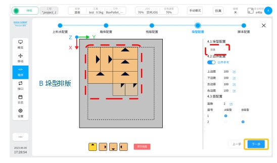
Figure 29
script configuration#
1、 Teaching three teaching points and their pullback points, as shown in Figure 30.

Figure 30
Figure 30 (1) Position: teaching “waiting for loading point”
As shown in Figure 31, click the teaching point and move the robot to the position between the pallet and the feeding point
Raise to a certain height in the negative direction of the Z-axis of the world coordinate system (does not affect interference with other objects in subsequent motion)
Click the “Record current position” button
FIG. 31
Position (2) in FIG. 30: Teach “loading obstacle avoidance point”
Operate the robot to move to the loading point (loading point Configuration section)
As shown in Figure 32, click on the teaching point and lift up (along the normal direction of the top surface of the box).
Similarly lift to a certain height (above the height position of the “feed back point”)
Click the “Record current position” button
As shown in Figure 30, “Feed back point” : Enter the height value (mm), the height is greater than 10mm
If there is a boot block, the height value is greater than the height of the boot block, as shown in Figure 32

FIG. 32
Position (3) in FIG. 30: Teach “pallet obstacle avoidance point”
Click the teaching point and move the robot to the top of the pallet
As shown in Figure 33, lift up (along the normal side of the top surface of the box)
Similarly lift to a certain height (higher than the height of the top box of the stack)
Click the “Record current position” button
As shown in Figure 30, “Place a retracement point” : Enter the height value (mm), which is greater than 10mm
Figure 33
2、 Interlayer tolerance setting (in Figure 35), the effect is shown in Figure 34.
Enter the value of interlayer tolerance, the range is [-100, +100], the unit is mm
Enter a positive value to expand the spacing between layers
Enter negative values to press the spacing between layers
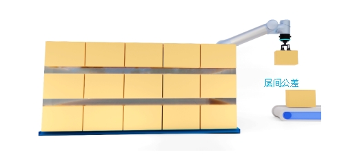
Figure 34
3、 Motion speed, as shown in Figure 35.
As shown in Figure 35, the speed or speed of the actual motion can be adjusted by pulling the percentage

Figure 35
4、 Reachability test, as shown in Figure 35.
“Whether there is a lifting platform” : If the device is available, turn it on, and if not, turn it off
Lift Table Travel: Enter the actual value
“Accessibility Test” :
Check whether all boxes on the pallet can be placed in place
Test results are for reference only
Click the “Finish” button to jump to the program interface, as shown in Figure 36
Click the “OK” button to complete the configuration of BoxPallet module and generate script, as shown in Figure 37

FIG. 36

Figure 37
Script optimization#
1、 Set parameters of the “Start” module, as shown in Figure 38.
Operate the robot to move to the position of “waiting for loading point”
Click “Record current point” button, click “Confirm button”

Figure 38
2、 Set the “Group waiting signal” module, as shown in Figure 39.
By adding instructions, the robot continues to grab the box and start stacking
There are three ways to add instructions:
Example Setting an I/O port
Set up communication module
Set up the “Wait” module (execute according to fixed wait time)
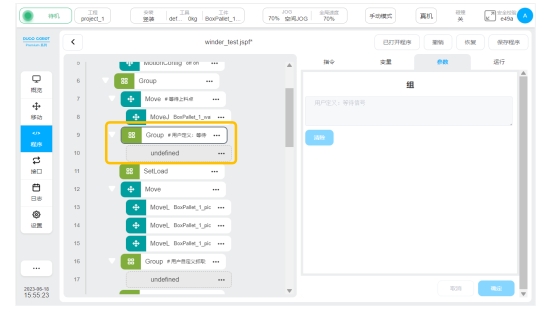
Figure 39
3、Set up the “Group custom crawl” module, as shown in Figure 40.
Add instructions to set the fetching mode
It can be realized by setting the I/O interface and communication

FIG. 40
4、 Set the “Group custom lifting platform lifting” module, as shown in Figure 41.
Position (2) in the figure: the “Group lifting platform” module can raise the height of the lifting platform by loading the command module
Positions (1) and (3) in the figure: “Group middle waypoint” module. You can add new waypoints by loading the command module to prevent path interference during script running
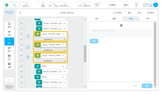
Figure 41
5、Set the “Group Custom placement” module, as shown in Figure 42.
Add instructions to set how to place the box
The box can be placed by setting the I/O interface and communication
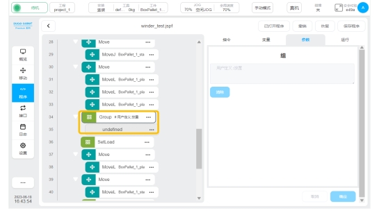
FIG. 42
6、 Set the “Group custom lifting platform lowering” module, as shown in Figure 43.
Position (2) in the figure: the “Group lifting platform lowering” module can reduce the height of the lifting platform by loading the command module
Positions (1) and (3) in the figure: “Group middle waypoint” module. You can add new waypoints by loading the command module to prevent path interference during script running

Figure 43
7、 The robot returns to the initial position of the script, as shown in Figure 44.
Click the “Save Program” button
Click the “Drag Move” button
The robot moves in the mode of movej. Releasing stops the movement. In order to prevent the movej from bumping into other objects in its path, it is recommended that the user return to the waiting point in advance in a manual jog

Figure 44
Click as shown in Figure 45

Button to start running the script
Using Manual Mode, select Simulation mode to run the entire process
Use Manual Mode and select Real Machine mode to run the entire process
If trajectory interference or singularity occurs after the above two processes are executed, add instructions to the “Group Custom intermediate waypoint” module in the script and set a new waypoint to solve the problem
Using “Real Machine” mode, click “Automatic Mode” to run the whole process
The user can adjust the robot running speed by clicking the “global speed” button to make the rhythm meet the production demand
Click the “Save Program” button to solidify the entire script

FIG. 45