External shaft Process package Settings#
External shaft process package setup, including external shaft configuration, external shaft scheme configuration two parts.
External axis configuration#
The external shaft configuration page displays basic information such as shaft name, shaft type, and shaft position. You can click the shaft position, enable or disable the shaft, and configure shaft parameters. One external axis corresponds to an actual single degree of freedom servo unit.
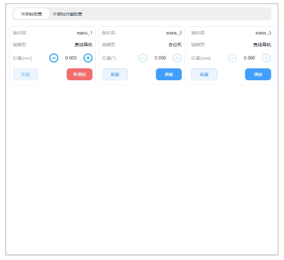
Click the “Enable” button, after the external axis is enabled, you can hold down the left side of the axis position display

Icon or right

The icon moves the external axis in the opposite direction or in the positive direction. When the external shaft break is enabled, the shaft cannot be clicked.
Click the “Configure” button, the external shaft parameter configuration box will pop up as shown below. The configurable parameters include shaft type, shaft control mode, reference speed, reference acceleration, maximum speed, maximum acceleration, encoder type, encoder resolution, zero offset, lead, direction of motion, upper limit and lower limit. After external axis is enabled, external axis parameters cannot be configured.
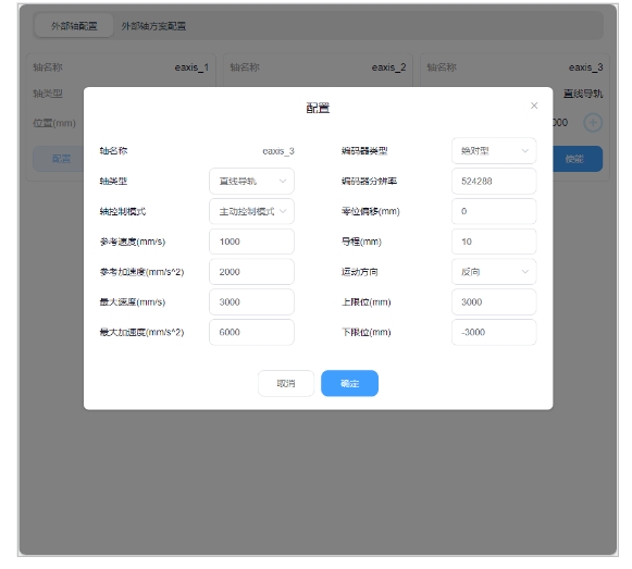
Shaft type: linear guide or positioner;
Axis control mode: active control mode or cooperative control mode. In the active control mode, the external axis is directly generated and controlled by the robot controller for planning instructions; In the cooperative control mode, the external axis is controlled by an independent controller and interacts with the robot controller. The robot performs cooperative control based on the external axis instructions, and the robot maintains a specific relationship with the external axis coordinate system.
Reference speed: This speed will be used as the reference speed when the external axis is moving, in mm/s or °/s;
Reference acceleration: This acceleration will be used as the reference acceleration of the external axis point motion in mm/s^2 or °/s^2;
Maximum speed: This speed will be used as the maximum speed constraint and monitoring parameter when the external shaft is jointly planned, the unit is mm/s or °/s;
Maximum acceleration: This acceleration will be used as the acceleration constraint and monitoring parameter of the external axis jointly planning the movement, in mm/s^2 or °/s^2;
Encoder type: incremental or absolute;
Encoder resolution: no dimension parameter, to convert the encoder communication data cnt number into the actual Angle value of the scale factor, encoder cnt/ encoder bit = the actual Angle;
Zero offset: display configurable and effective only when the encoder type is absolute, the default is 0, the unit is mm or °, the user can directly modify or quickly modify by setting the current position to zero;
Lead: It is configurable and effective only when the external shaft type is linear guide. The unit mm is used to describe the displacement distance generated by the linear guide when the encoder rotates 360°. The encoder cnt/ encoder position * lead = the actual position of the linear guide.
Direction of motion: forward or reverse, describing the relationship between the encoder increasing direction and the actual axis movement direction, the forward is the same direction, the reverse is the opposite reverse;
Upper limit/lower limit: describes the absolute range of motion of the external axis with reference to the current zero position. Exceeding the limit will trigger the corresponding safety stop operation, in mm or °.
External axis scheme configuration#
On the External Axis Configuration page, you can create an external axis scheme or edit or delete an existing external axis scheme. The left area of the page is the external axis scheme navigation TAB, and the right area is the external axis scheme parameter content displayed in the corresponding external axis scheme TAB, as well as all enable/disable, external axis calibration, and external axis click buttons.
Click on the upper right corner of the left area of the page

Icon, the virtual keyboard will pop up as follows:

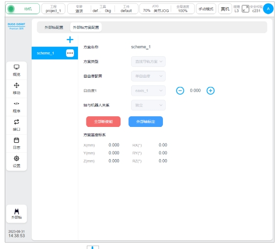
After you enter the name of the external axis scheme to be created, scheme_test is displayed as shown in the following figure. In the left navigation TAB, the new external axis scheme name scheme_test is displayed. The font color is red, indicating that the external axis scheme is invalid, that is, the scheme whose parameters are not configured. The external axis scheme is valid only if the font color is black. The content area on the right shows the content to be configured for the new external axis scheme. The configurable parameters include scheme type, freedom configuration, and the relationship between the axis and the robot.
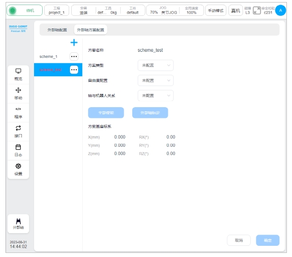
Scheme type: linear guide scheme or positioner scheme;
Freedom configuration: The linear guide scheme currently only supports single freedom, and the positioner scheme supports single freedom and two degrees of freedom. After the degree of freedom is selected, the degree of freedom can be bound to the external axis according to the selected degree of freedom. As shown in the figure below, the degree of freedom of the single-degree-of-freedom linear guide scheme 1 binds the external axis of the linear guide eaxis_3;
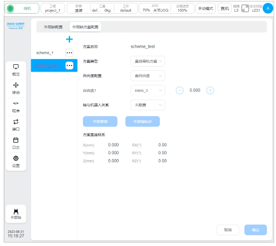
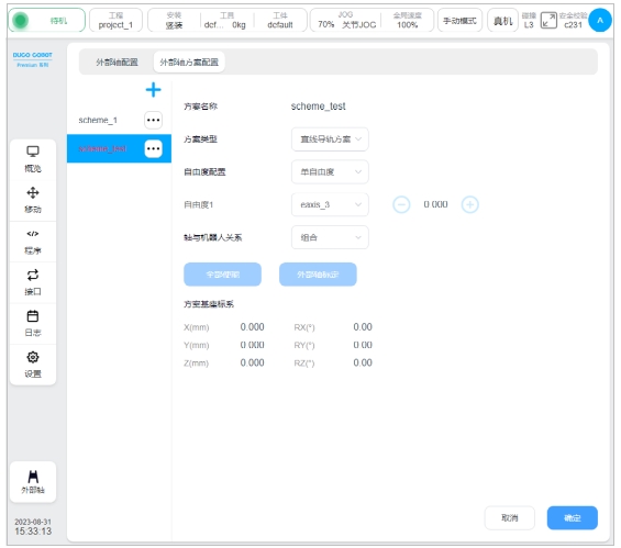
Axis and robot relationship: independent or combined, that is, the external axis is independent of the robot or the robot is fixed on the external axis;
Solution base coordinate system: It is used to describe the position of the external axis base coordinate system in the world coordinate system. By default, it coincides with the world coordinate system. The coordinate system is calibrated through the external axis calibration process.
After the above configurable parameters are set, click OK at the lower right corner of the page to complete the configuration of the external axis scheme.
In the editing state of the external axis scheme, the buttons of “Enable all” or “Disable All” and “External axis calibration” on the page are disabled, and the click operation button of the external axis cannot be operated. Enable/disable the external axis scheme and calibrate the external axis scheme can be performed only when the external axis scheme is not in the edit state, and the external axis click button can be operated only when the external axis scheme is enabled, that is, the click operation can be performed only when all external axes are enabled.

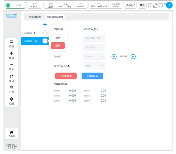
Click on the left side of the page after the external axis scheme name

Icon, a pop-up box showing “Edit” and “Delete” buttons, you can edit or delete the selected external axis scheme.
External axis calibration#
The external axis calibration process is used to calibrate and calculate the base coordinate system of the external axis scheme. In the non-editing state of the external axis scheme, click the “External axis calibration” button on the page to enter the external axis calibration process page. According to the different types of external shaft, external shaft calibration is also divided into linear guide calibration and positioner calibration.
Linear guide calibration#
According to the different types of relationship between shaft and robot, linear guide calibration is also divided into two types: combination and independent. This section uses the external axis scheme scheme_test as an example to describe the calibration flow of the combined linear guide scheme.
Click the “External axis calibration” button on the page, as shown below:
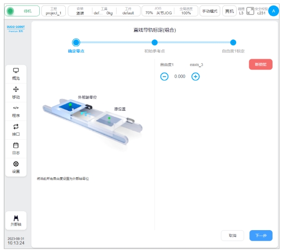
1、 Determine the zero point: You can press and hold the ICONS on the left and right sides of the display of the external axis position, move the external axis, determine the external axis zero point position, and click the “Next” button;
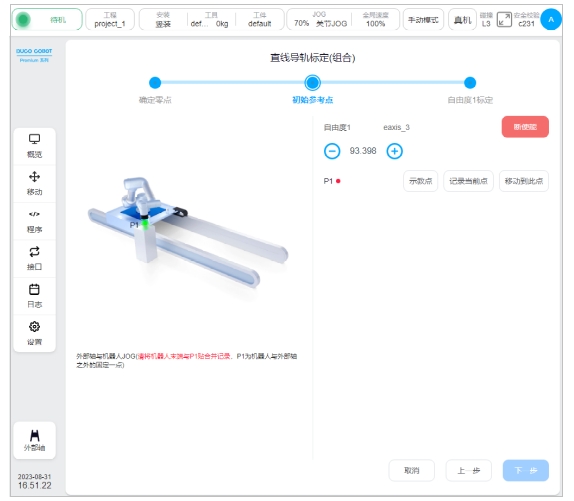
2、Initial reference point: P1 point is a fixed point outside the robot and the external axis, JOG the external axis and the robot respectively, so that the end of robot and P1 point paste merge records; After teaching the robot or the external axis position, the P1 point will be displayed as, click the “Next” button;
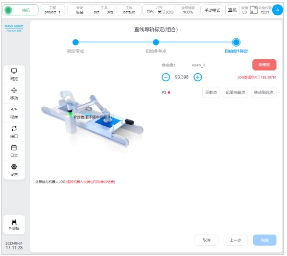
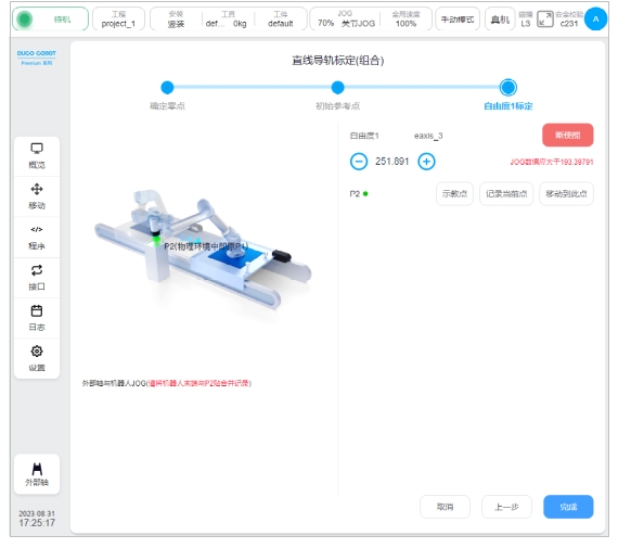
3、 the degree of freedom 1 calibration: JOG the external axis and the robot in the same way, so that the end of robot and P2 point (in the physical environment is the original P1 point) paste combined records; After teaching and recording the position of the end of robot, click “Finish”.
Calibrating of positioner#
When the type of the external axis is a positioner, the calibration of the external axis is the calibration of the positioner. In this paper, the calibration process of single-degree-of-freedom positioner type external axis scheme is introduced. Click the “External axis Calibration” button on the page as shown below:
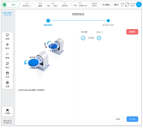
1、 Determine the zero point: You can press and hold the ICONS on the left and right sides of the display of the external axis position, move the external axis, determine the external axis zero point position, and click the “Next” button;
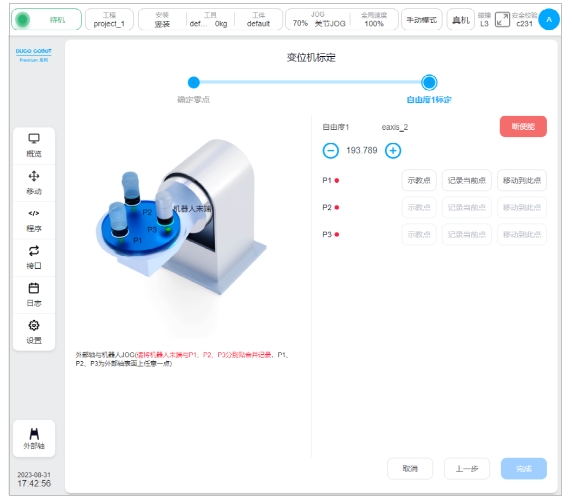
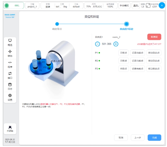
2、 degrees of freedom 1 calibration: P1, P2, P3 are any point on the surface of the external axis, JOG the external axis and the robot, so that the end of robot and P1, P2, P3 are attached to the combined record; After teaching and recording the position of the end of robot, click “Finish”.
External axis programming function block#
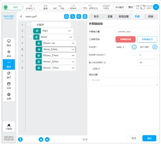
There are four functional blocks related to the external axis: Move_Eaxis, MoveJ_Eaxis, MoveL_Eaxis, MoveC_Eaxis.
Move_Eaxis
An instruction block for the external axis to move separately. Parameters available:
External axis scheme: Name of the target external axis scheme.
Freedom target point: the position of freedom corresponding to the target external axis scheme, record the position freedom and the unit of freedom set according to the external axis scheme and the type of external axis scheme change, the unit is ° or mm.
Maximum planned speed: Maximum planned speed of an external axis. The unit is °/s or mm/s, depending on the external axis scheme type.
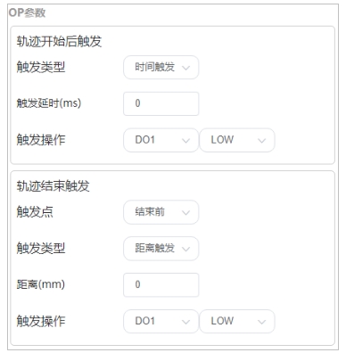
Enable OP: The OP feature allows you to set generic digital outlet states or manipulate custom events during track execution.
If OP is enabled, you need to perform the following configurations:
It can be triggered after the start of the trajectory and before/after the end of the trajectory
Trigger type: You can select no trigger, time trigger, distance trigger
Trigger delay: Set time (unit: ms)
Trigger distance: Set the distance, in mm
Trigger action: Select a port and port status, or perform a custom event
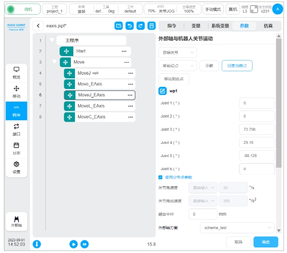
MoveJ_Eaxis
The external axis moves with the robot joints. The robot moves in the manner of joint motion, and can choose to move to the target joint or the target posture. Parameters available:
Target position: It can be set by teaching or set as a variable, and can be changed manually after teaching setting.
Use parent node coordinate system: This parameter can be set when the target position posture is selected. If this parameter is selected, the function block uses the reference coordinate system set by the parent node Move function block
Reference coordinate system: can be set when the target position posture is selected. If the parent coordinate system is not checked, its reference coordinate system can be set separately for the function block
Use parent node parameters: When selected, the function block uses the joint angular velocity and joint angular acceleration parameters set by the parent node Move function block. If this parameter is not selected, you need to set the joint angular velocity and joint angular acceleration for this function block. This parameter is selected by default
Joint angular velocity: Unit °/s, variable can be directly entered or selected.
Joint angular acceleration: Unit °/s2, variable can be directly entered or selected.
Fusion radius: The unit mm0 indicates no fusion.
Enable OP: The OP feature allows you to set generic digital outlet states or manipulate custom events during track execution.
The external axis parameter configuration is the same as Move_EAxis, which is not covered here.
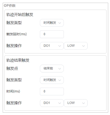
If OP is enabled, you need to perform the following configurations:
It can be triggered after the start of the trajectory and before/after the end of the trajectory
Trigger type: You can select no trigger, time trigger, distance trigger
Trigger delay: Set time (unit: ms)
Trigger action: Select a port and port status, or perform a custom event
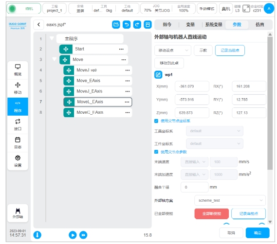
MoveL_Eaxis
The external axis moves in a straight line with the robot. The robot moves to the target position in a straight line. Parameters can be set:
Target posture: It can be set by teaching or set as a variable, and can be changed manually after teaching setting.
Parent coordinate system: If this parameter is selected, the function block uses the reference coordinate system set by the parent Move function block. This parameter is selected by default
Reference coordinate system: If the parent coordinate system is not selected, the reference coordinate system can be set separately for the function block
Use parent node parameters: When checked, the function block uses the end speed and end acceleration parameters set by the parent node Move function block. If you do not select this option, you need to set the end speed and end acceleration for this function block. They are selected by default
Terminal speed: In mm/s, a variable can be directly entered or selected.
Terminal acceleration: Unit mm/s2, can be directly entered or selected variables.
Fusion radius: Unit: mm. 0 indicates no fusion
Enable OP: The OP feature allows you to set generic digital outlet states or manipulate custom events during track execution.
The OP parameters are configured as Move_EAxis.
The external axis parameter configuration is the same as Move_EAxis, which is not covered here.
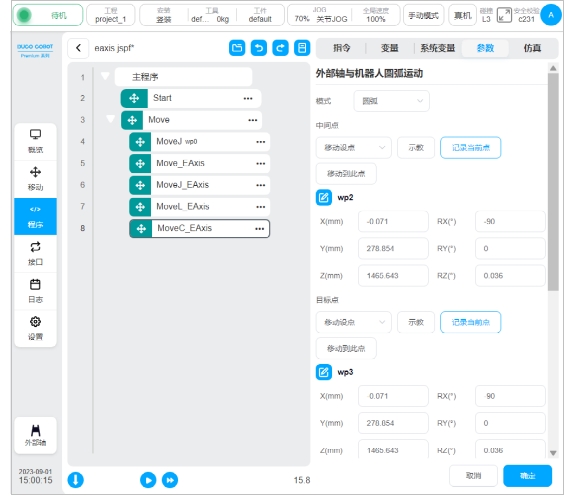
MoveC_Eaxis
The external axis moves in an arc with the robot. Robot moves according to arc or whole circle, parameters can be set:
Mode: Arc or full circle
Intermediate point posture/intermediate point 1: can be set by teaching or set as a variable, and can be changed manually after teaching setting.
Target posture/middle point 2: It can be set by teaching or as a variable, and can be changed manually after teaching setting.
Parent coordinate system: If this parameter is selected, the function block uses the reference coordinate system set by the parent Move function block. This parameter is selected by default
Reference coordinate system: If the parent coordinate system is not selected, the reference coordinate system can be set separately for the function block
Use parent node parameters: When checked, the function block uses the end speed and end acceleration parameters set by the parent node Move function block. If you do not select this option, you need to set the end speed and end acceleration for this function block. They are selected by default
Terminal speed: In mm/s, a variable can be directly entered or selected.
Terminal acceleration: Unit mm/s2, can be directly entered or selected variables.
Fusion radius: Unit: mm. 0 indicates no fusion
Posture control mode: If “consistent with the end point” is selected, the robot’s posture plans the posture in the arc path according to the end point; If “consistent with the starting point” is selected, the robot’s posture in the arc path is planned according to the starting point’s posture, and the posture in the path process is consistent with the starting point. If “constrained by the center of the circle” is selected, the posture of the robot is constrained relative to the posture change generated by the arc motion.
Enable OP: The OP feature allows you to set generic digital outlet states or manipulate custom events during track execution.
The OP parameters are configured as Move_EAxis.
The external axis parameter configuration is the same as Move_EAxis, which is not covered here.