Safety Settings#
This section describes how to view safety configurations and change application safety configurations. There are currently two types of safety controllers, DucoSafetyV1.0 for DC30 control cabinets. DucoSafetyV2.0 ADAPTS to DC00 / DC15S/ DC30D control cabinets.
DucoSafety V1.0#
View Safety Configurations#
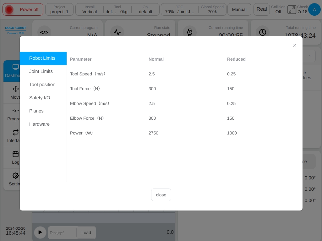
Click the ‘Safety Verification’ button on the status bar. The following dialog box is displayed to view the currently activated safety configuration parameters.
The user can also view the safety configuration parameters on the safety setting page.
Safety Configuration Change Application#
You must use the password to unlock the account before changing the safety configuration. Enter the setting page – safety configuration, click the ‘Unlock’ button at the bottom left to unlock the robot only when the power is off. Entering the password (login password of the current user) them enter the safety parameter configuration mode after the verification is passed. The status area on the status bar is displayed as Safety Parameter Settings.

When you change the configuration, the modification will be highlighted in yellow. All changes made will only take effect when the ‘Apply Settings’ button is clicked. By clicking the ‘Restore Default Settings’ button to restore all the safety parameters to the default settings. After clicking the ‘Apply Settings’ button a prompt box will pop up as shown in the picture.
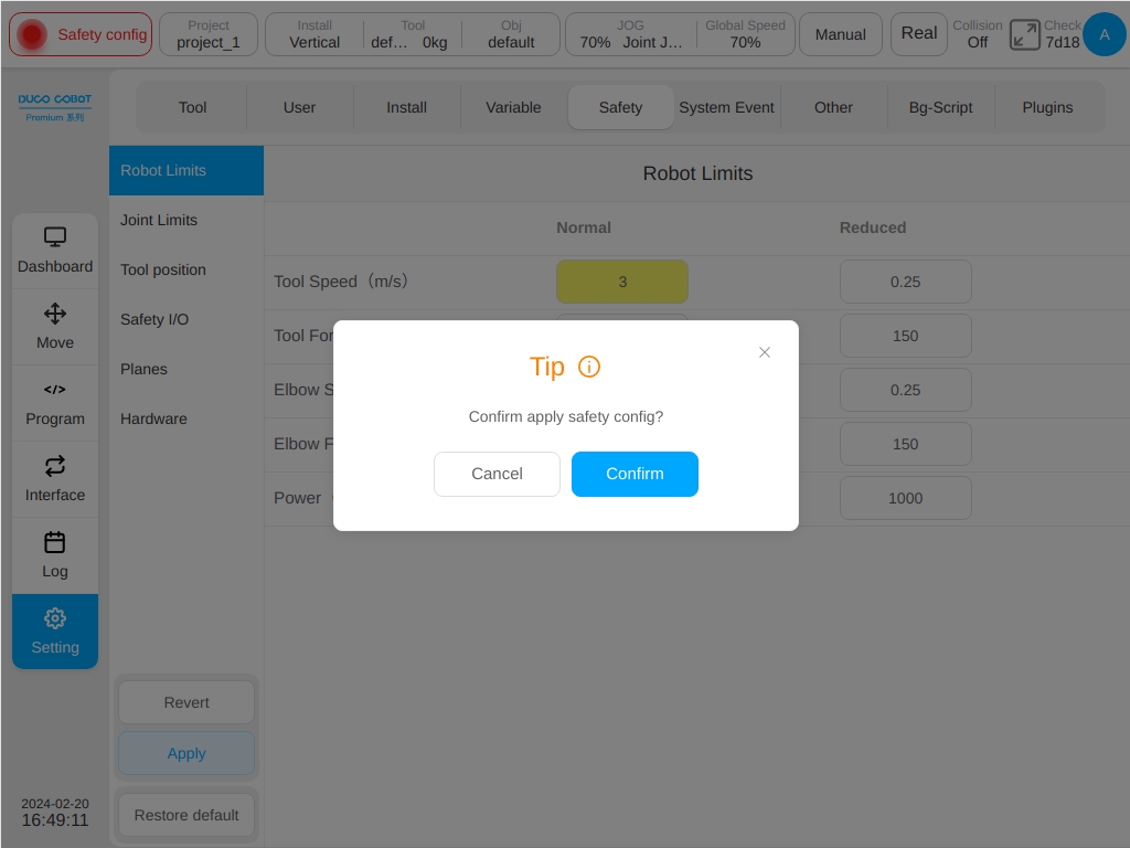
After clicking the ‘Confirm’ button, a prompt box for loading safety parameters will be displayed as shown in the figure.
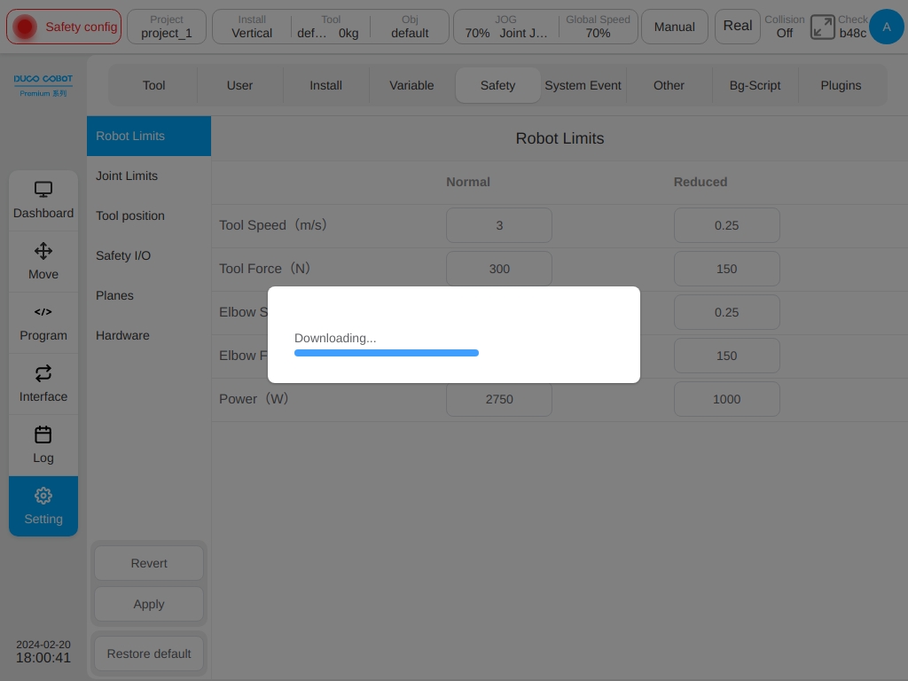
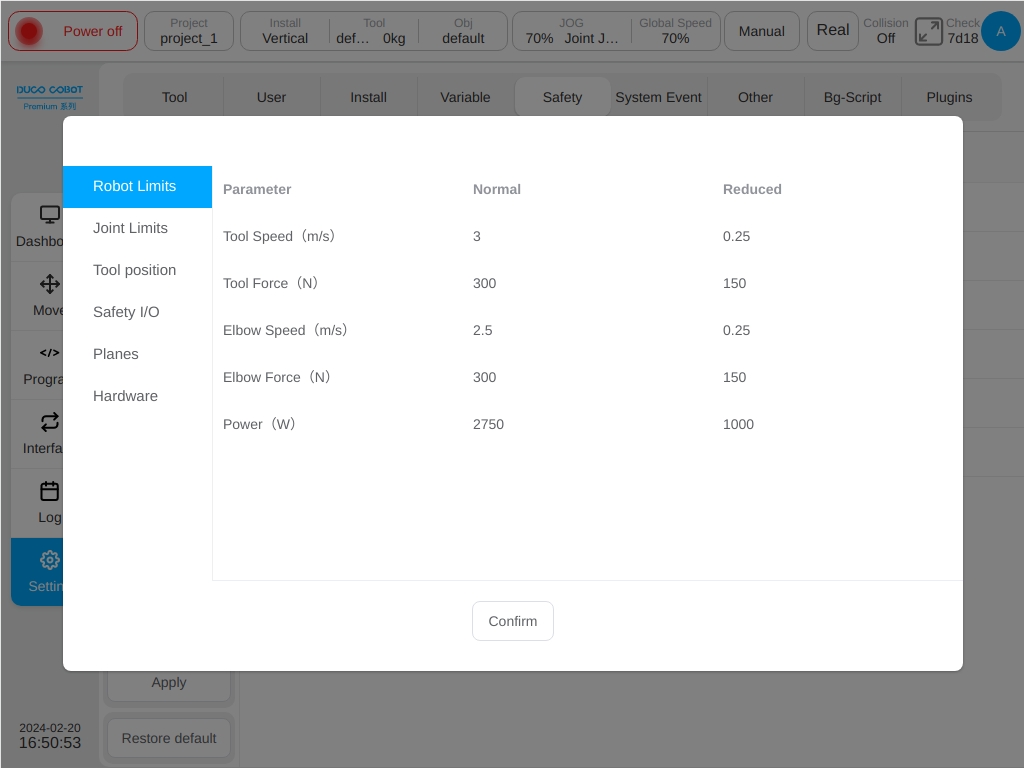
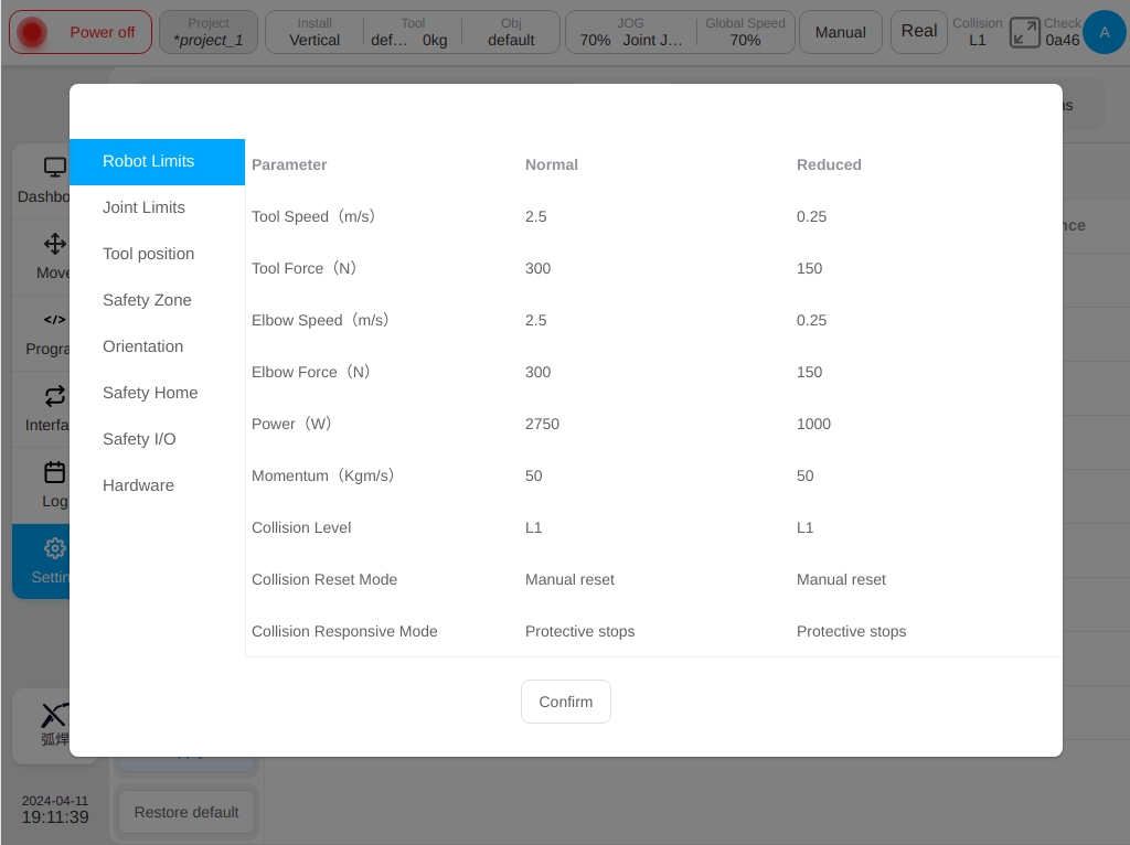
After the safety parameters are configured, the system displays the configured safety parameters in a dialog box for checking purpose. As an example shown in the following figure. Once everything is checked click the ‘OK’ button to set the safety parameters. After the configuration succeed, the safety check above the status bar is changed.
Safety Parameter Description#
This section describes the safety configuration parameters of the robot.
Safety Mode#
Normal Mode:The safety mode is activated by default
Reduced Mode:This mode can be activated using safety input IO
Recovery Mode:When the actual motion parameters of the robot exceed the safety limit, causing the robot to stop, the recovery mode will be activated, and the user can move the robot within the safety limit
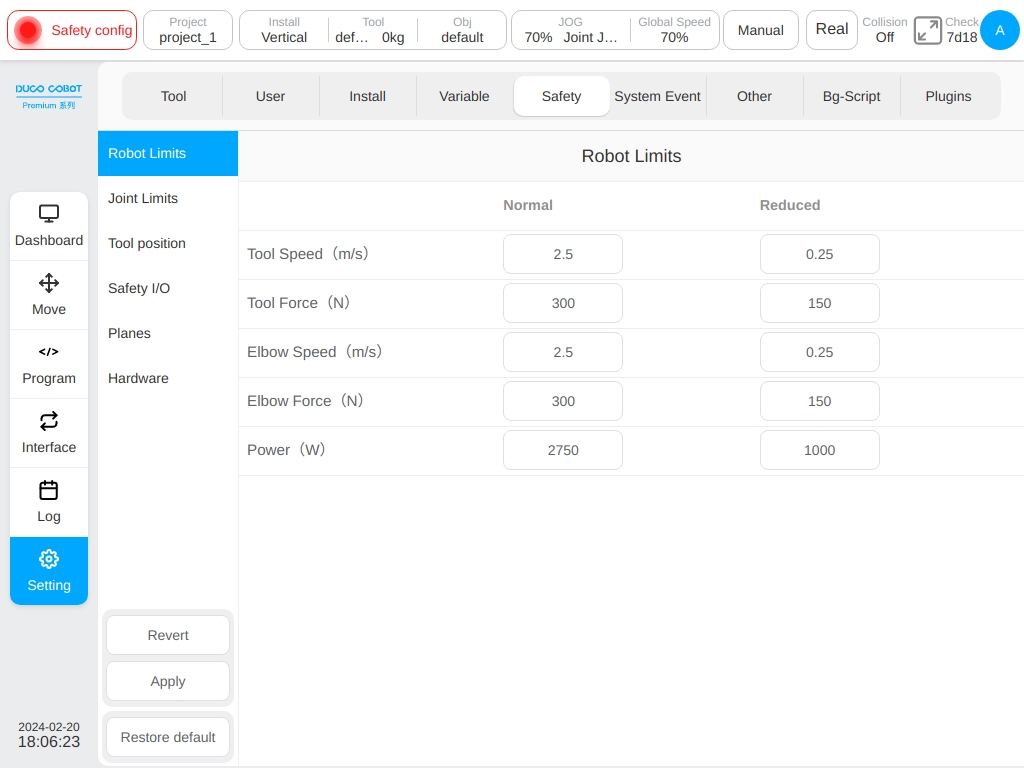
Robot Safety Parameters#
Robot parameters are used to limit general robot motion. The user can configure its parameter values in normal mode and reduced mode.
Maximum End Speed Limits the maximum speed at the end of the robot.
Maximum Force at the End Limits the maximum force applied externally at the end of the robot.
Maximum Elbow Speed Limits the maximum elbow speed of the robot.
Maximum Elbow Force Limits the maximum external force applied by the robot’s elbow.
Power Limit the maximum amount of mechanical work done by the robot to the exterior.
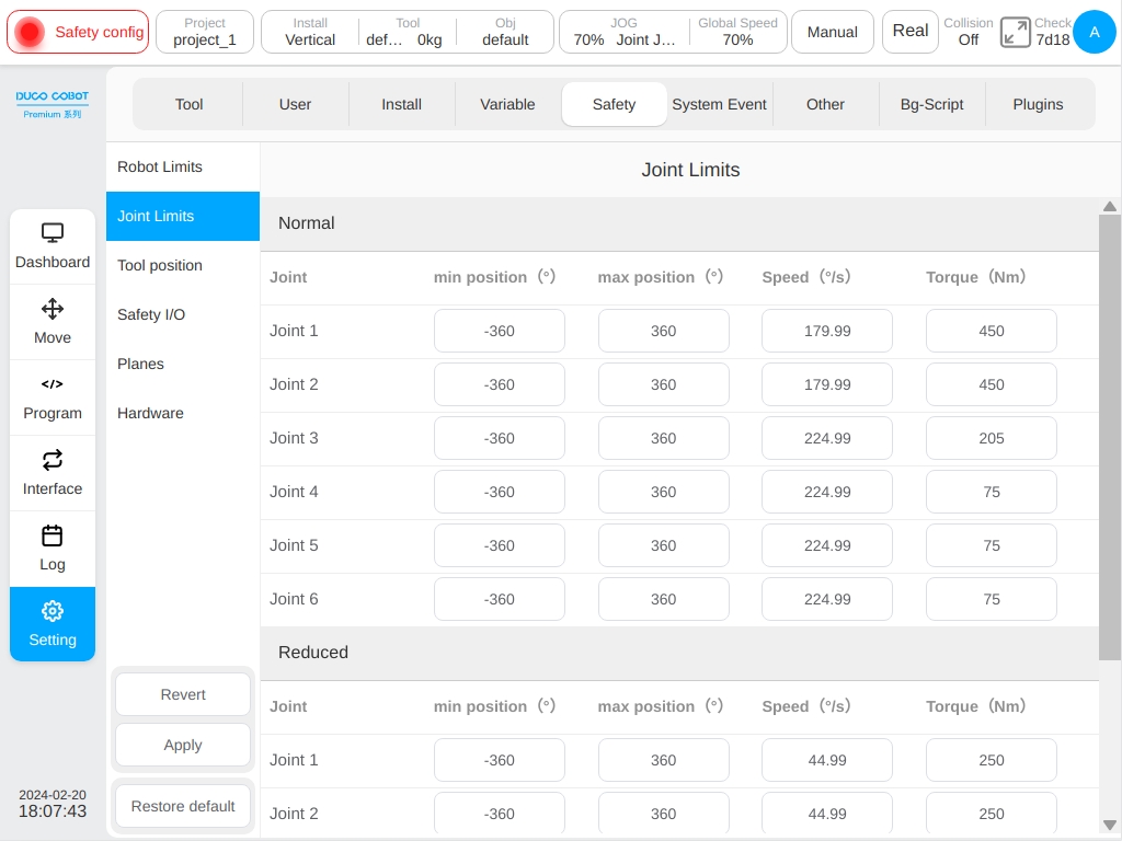
Joint Safety Parameters#
Joint parameter limit is used to limit the position range, maximum speed and maximum torque of each joint of the robot. You can configure its parameter values in normal mode and reduced mode
Position Range:Defines the minimum and maximum positions of each joint.
Maximum Velocity:Defines the maximum angular velocity of each joint.
Maximum Torque:Define the maximum torque of each joint
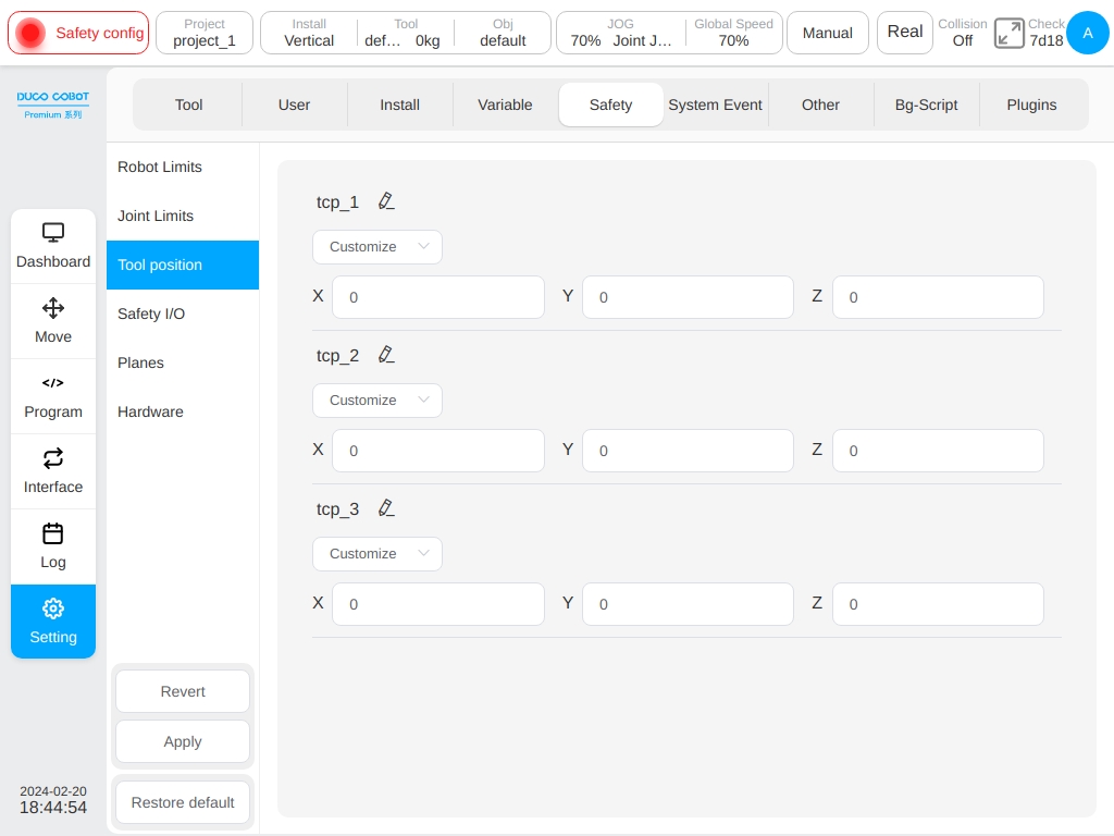
Safety TCP#
The safety system can define three sets of TCP offsets, when configured, it will used by robot for speed monitoring and position monitoring. Any TCP position or speed exceeding the safety setting will trigger a safety violation.
Speed monitoring is the maximum speed of the tool among “Robot Safety Parameters”. Position monitoring is also called “Virtual Boundary”. In the drop-down box, you can select an existing TCP or customize the XYZ value directly. When you select an existing TCP and change the value in the X, Y, and Z input fields, the TCP name in the drop-down menu will become ‘Custom’, indicating the newly defined TCP.
Modifying the TCP settings does not affect the configured safety parameters.
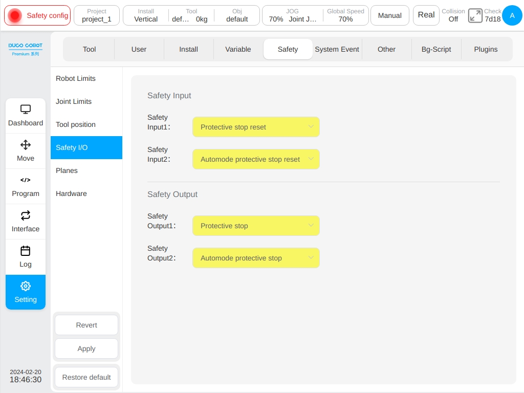
Safety IO#
The safety I/O module contains two configurable safety input ports and two configurable safety output ports.
Safety input features include:
Guard Reset Input:When the guard stop occurs, the port is triggered and the robot returns to normal state
Automatic Mode Protective Stop Input:After configuration, when the robot triggers the port in automatic mode, the robot performs a protective stop.
Automatic Mode Protection Reset Input:When automatic mode protection stops, the port is triggered and the robot returns to normal state.
Reduced Mode Input:After configuration, this port is triggered and the robot will transition to the reduced mode. The robot will slow down so that the parameter limits meet the safety parameter limits in the reduced mode.
Safety output features include:
Guard Stop Output:This port is triggered when the robot is in the guard stop state
Automatic Mode Guard Stop Output:This port is triggered when the robot is in automatic mode guard stop
Reduced Mode Output:This port is triggered when the robot is in the reduced mode.
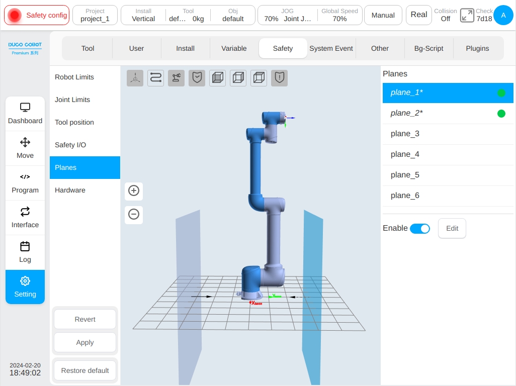
Virtual Boundary#
Virtual boundaries can be used to limit the robot’s workspace. Six virtual boundaries can be defined to limit the robot’s tools and elbows. When the robot’s tools and elbows touch the virtual boundary, the robot will perform a guarded stop.
The green indicator on the right side of the interface indicates that the plane is activated. while the 3D display can show the location of the activated virtual boundary and the effective area of the virtual boundary. When a plane is selected, the corresponding plane will be highlighted on the 3D display.
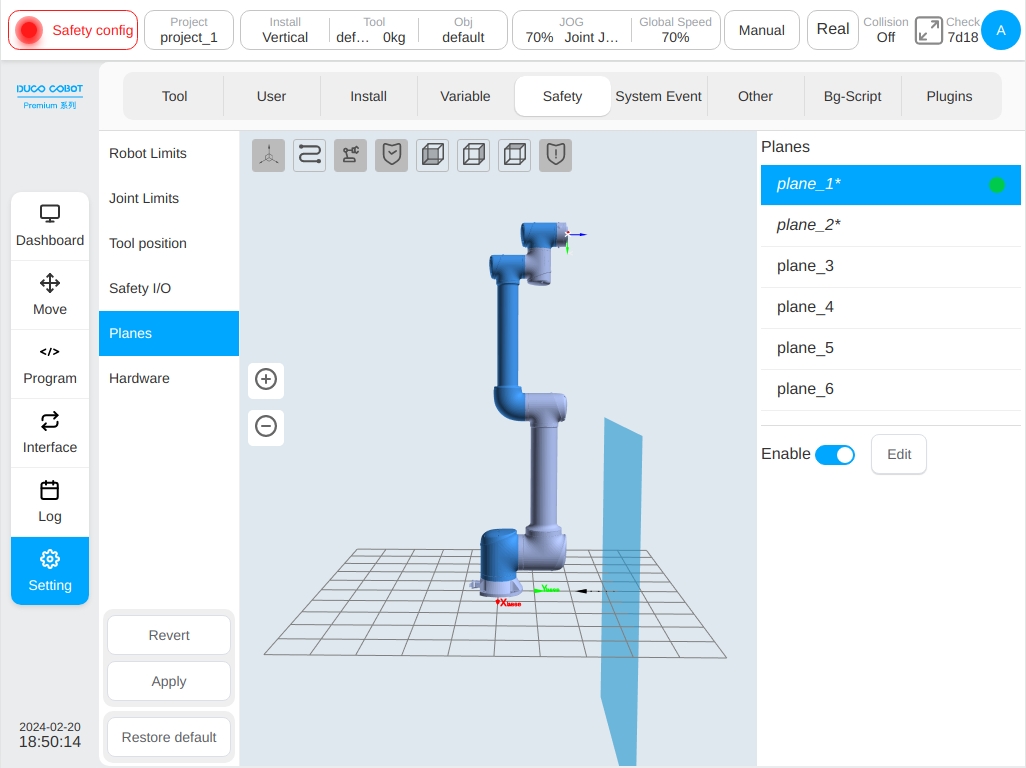
Virtual boundaries are defined in the following ways:
Select a reference coordinate system, which can be the world coordinate system, the base coordinate system, or the workpiece coordinate system defined in the setting; select one of the axes (X, Y, Z) of the reference coordinate system as the normal axis of the virtual plane, and set the offset distance along the axis; a positive value of the offset distance indicates a positive offset along the coordinate axis, and a negative value indicates a negative offset along the coordinate axis. In this way, a plane is determined, and then the effective activity area of the robot arm is selected to be on that side of the plane. For example, if the reference coordinate system is chosen as the base coordinate system, the Z-axis is chosen as the normal axis, and the offset distance is set to 600mm, then the virtual plane is formed by offsetting the XoY plane of the base coordinate system to the Z-axis in the positive direction by 600mm.
The following figure shows the corresponding interaction, select a plane, click the ‘Enable’ and the ‘Edit’ button, select the reference coordinate system, normal axis, enter the offset distance, select the effective area. Click the ‘OK’ button to define the virtual boundary, the arrows displayed on the virtual plane indicate the active area of the robot.
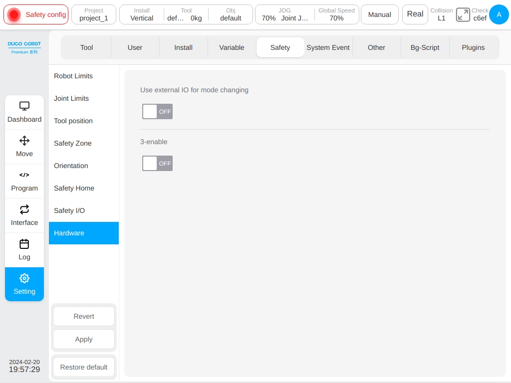
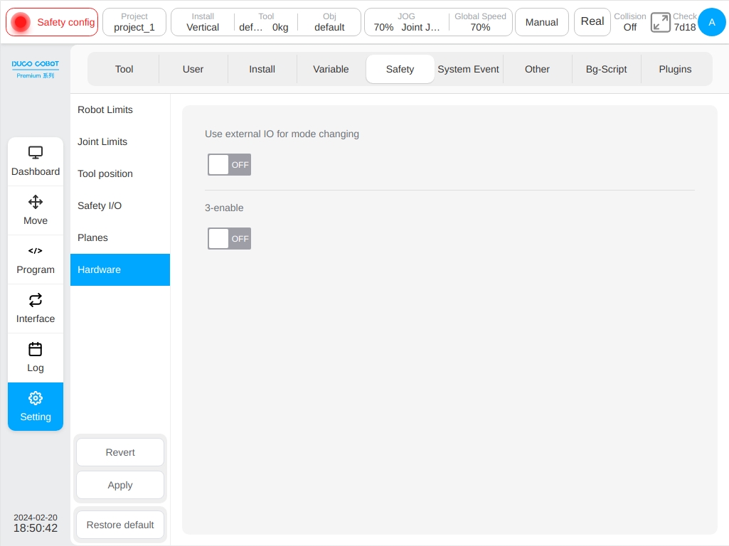
Hardware#
Includes enabling external IO for mode switching and three-position enable input.
Enable external IO for Mode Switching:When this item is enabled, manual mode switching can be performed through external IO. The mode switching function on the status bar of the interface is invalid.
Three-position Enable Input:When this item is enabled, meantime when the robot is in manual mode, the robot can be moved only when the three-position switch on teach pendant is in the middle position. When the three-position switch is in the non-middle position at any time during the movement of the robot, the stop function of the robot will trigger.
DucoSafety V2.0#
View Safety Configurations#
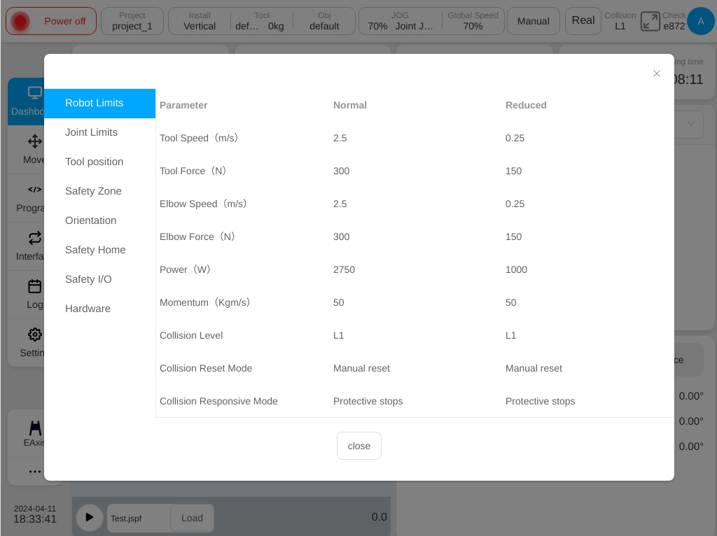
Click the ‘Safety Verification’ button on the status bar. The following dialog box is displayed to view the currently activated safety configuration parameters.
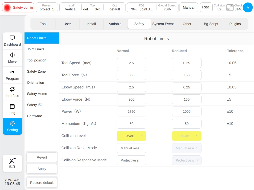
The user can also view the safety configuration parameters on the settings page - Safety settings.
Safety Configuration Change Application#
Before changing the security configuration, the user must use the password to unlock the robot. Entering the ‘Setup’ page - ‘Security Configuration’, click the ‘Unlock’ button on the lower left, only in the case of power failure can be unlocked, enter the password (the login password of the current logged-in user) and then enter the security parameter configuration mode after passing the verification. At this time, the status display area on the status bar shows ‘Security Parameter Configuration’.
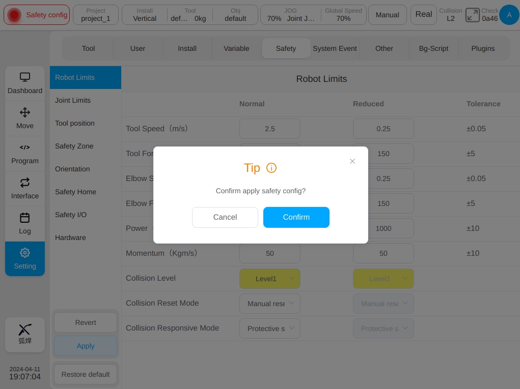
After clicking the ‘Confirm’ button, a prompt box for loading safety parameters will be displayed, as shown in the figure.
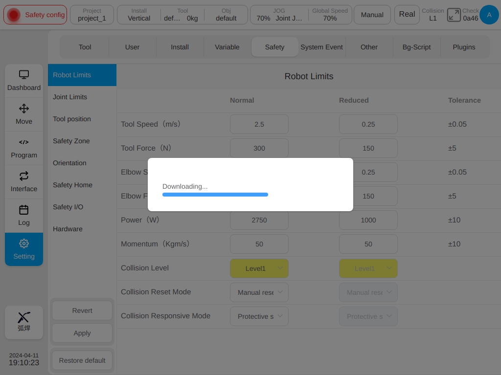
After the safety parameters are configured, the system displays the configured safety parameters in a dialog box for you to check. Check and confirm the following figure. Click the ‘OK’ button to set the safety parameters. After the configuration is successful, the safety check above the status bar changes.
Safety Parameter Description#
This section describes the safety configuration parameters of the robot.
Safety Mode#
Normal Mode:The safety mode is activated by default.
Reduce Mode:This mode can be activated using safety input IO.
Recovery Mode:When the actual motion parameters of the robot exceed the safety limit, causing the robot to stop, the recovery mode will be activated and the user can move the robot within the safety limit.
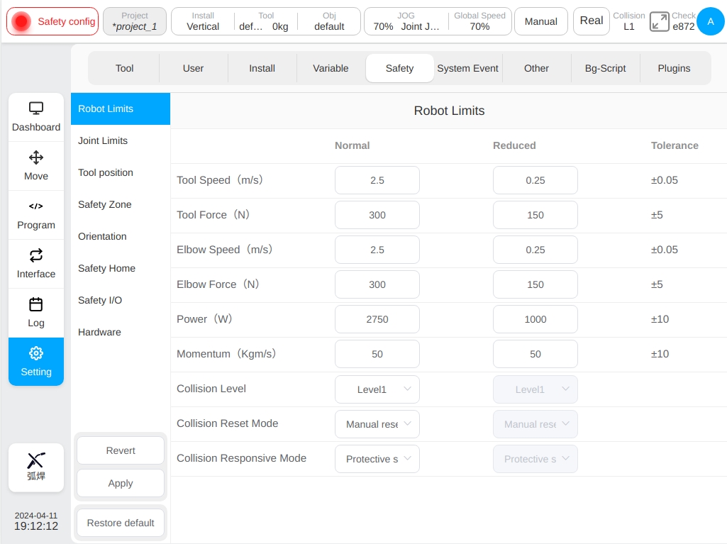
Robot Safety Parameters#
Robot parameters are used to limit general robot motion. The user can configure its parameter values in normal mode and reduce mode.
Maximum End Speed Limits the maximum speed of the end of the robot.
Maximum End Force Limits the maximum force applied externally at the end of the robot.
Maximum Elbow Speed Limits the maximum elbow speed of the robot.
Maximum Elbow Force Limits the maximum external force applied by the robot’s elbow.
Power Limits the maximum mechanical work done by the robot to the outside and the end of robot load is considered as part of the robot body.
Maximum Momentum Limits the maximum momentum of the robot output and the end of robot load is considered as part of the robot body.
Collision Detection Level Sensitivity of the robot to detect collisions with the outside world, the higher the level, the higher the sensitivity.
Collision Reset Mode A method for resetting the robot after a collision.
Collision Responsive Mode A method for responding the robot after a collision.
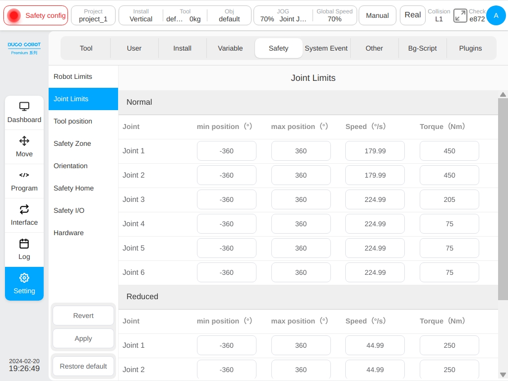
Joint Safety Parameters#
Joint parameter limit is used to limit the position range, maximum speed and maximum torque of each joint of the robot. The user can configure its parameter values in both normal mode and reduced mode.
Position Range:Defines the minimum and maximum positions of each joint.
Maximum Velocity:Defines the maximum angular velocity of each joint.
Maximum Torque:Defines the maximum torque of each joint.
Safety TCP and Tools#
The safety system can define three sets of TCP offsets, which, when configured, will be used by the robot for speed monitoring and location monitoring. Any one of the TCP position and speed exceeding the safety setting will trigger a safety violation.
Speed monitoring is the maximum linear speed of the robot’s safety TCP center in space in the ‘Robot Safety Parameters’ while location monitoring is also called the ‘Safe Area’. Three safety TCPs can be set while there are two ways to define the TCPs, either by choosing the tool coordinate system defined in the global variables or by customizing the value of the input coordinate system. When a predefined tool coordinate system is used, the tool coordinate system is selected and the value of the tool coordinate system is displayed in the X, Y, Z input box. If the X, Y, Z values are modified, the coordinate system becomes customized. If the value of the corresponding coordinate system in the global variable is modified and does not match the value of the coordinate system used in the current security settings a ‘!’ alert icon will pop up. When ‘Custom Input Data’ is selected, the values of X, Y, Z, Rx, Ry, Rz and the ball radius of the envelope are edited directly.
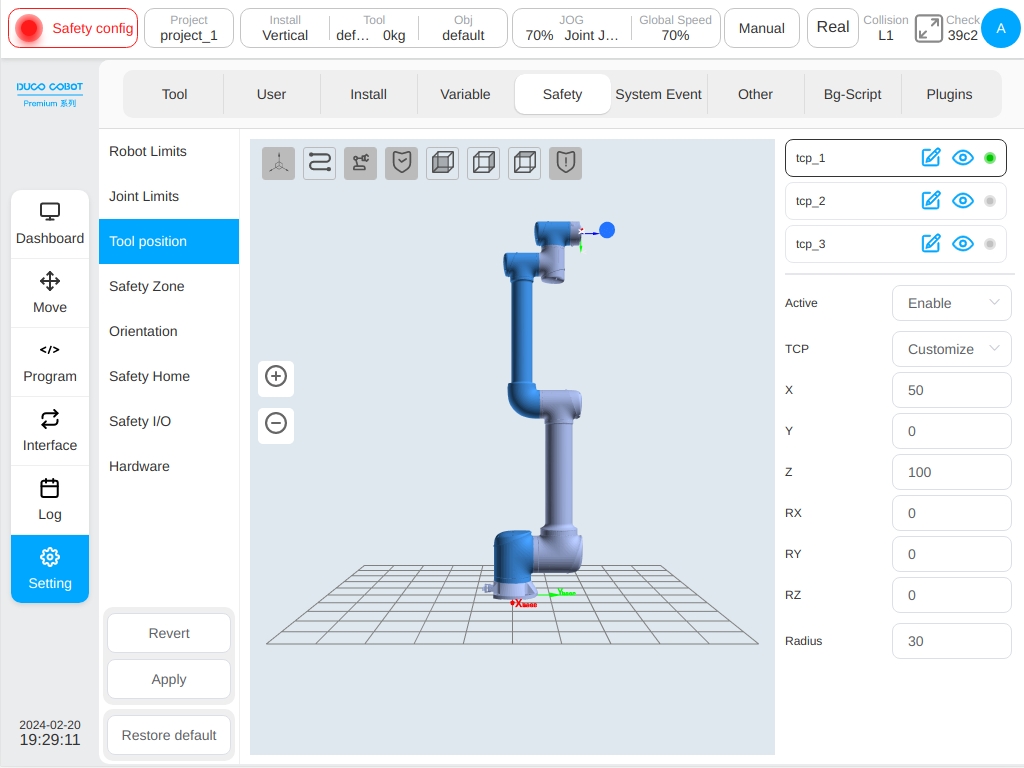
Each safety TCP can be set as disabled, always active, automatic mode active, safety combination configuration 1, safety combination configuration 2 overall five different kinds of activation conditions. When all three TCP are disabled, the safety control system defaults to a flanged coordinate system with a ball radius of 50mm. The TCP configuration status is displayed on the TCP configuration list. If a certain TCP is disabled, the corresponding status is displayed in grey. The configured safety TCP can display the coordinate system and envelope sphere in the 3D display area and can pass the corresponding TCP name with  icon is displayed and hidden. Click next to the TCP name
  Icon to change the default TCP name. The safety TCP that is not disabled is displayed
  . Otherwise, it will be displayed
  .
.
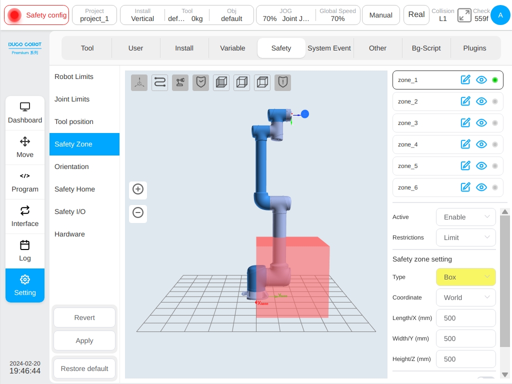
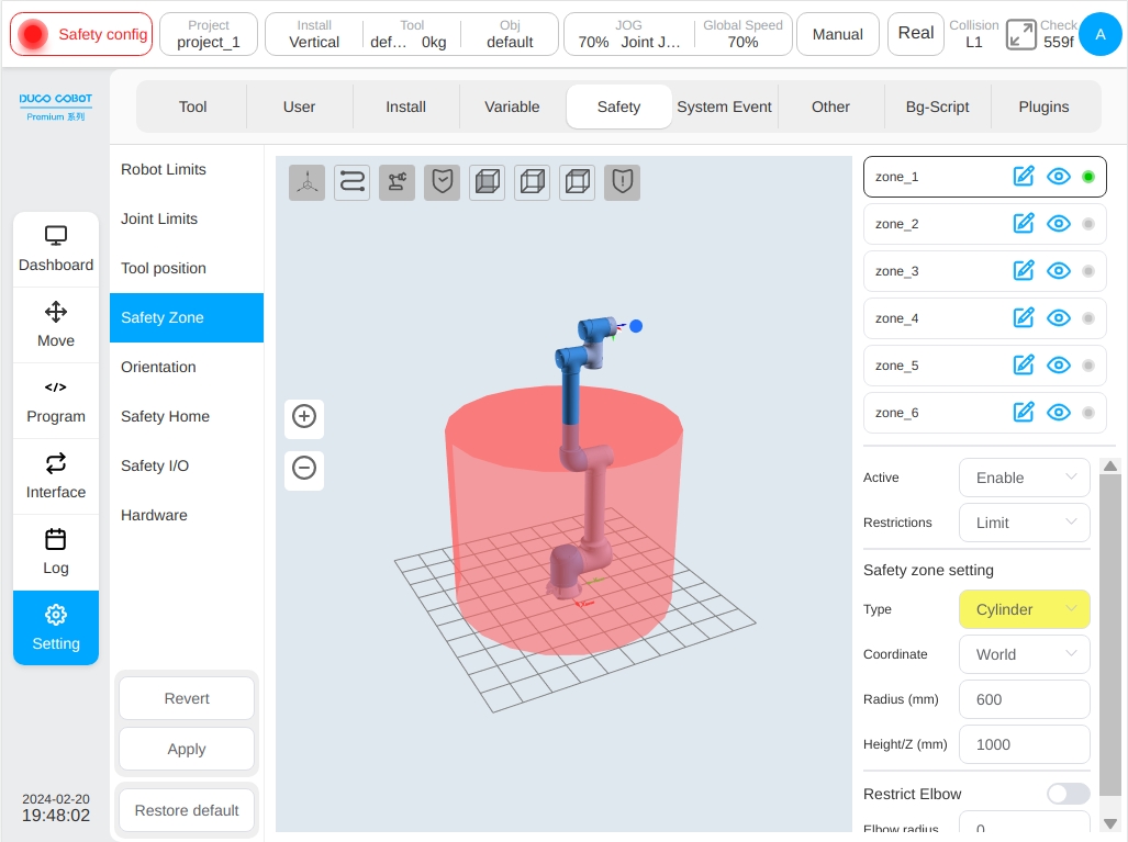
Safety Zone#
The definition types of safety zones include plane, rectangle and cylinder. Users can set up to six independent space zones. Click the icon next to the safety zone name to display or hide the configured security zone in the 3D display zone. And the icon next to the secure zone name (e.g. the default name zone_1) can be clicked to change its name. will be displayed if the secure zone is not disabled, otherwise will be displayed.
Safety zone activation configurations include: Disabled, Always active, Automatic mode active, Safety group configuration 1 and Safety group configuration 2.
The boundary response of the safety zone refers to the response of the robot entering the safety zone from the outside and moving beyond the boundary from the inside. There are two response modes, namely, limiting the movement beyond the boundary and triggering the reduce mode when entering the zone. When the selection limit exceeds the boundary, the response of the robot moving beyond the boundary is described. When the trigger reduce mode is selected, the response of the robot entering the zone from the outside is described, and the normal mode is restored when the robot leaves the zone.
The space zone can also be set to include elbow limits with the space range of the elbow is set in the form of a spherical radius.
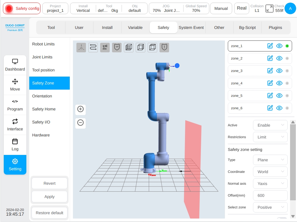
When the configuration zone type is plane, the reference of the plane zone is based on the world coordinate system/base/set workpiece coordinate system and the plane is determined by setting the normal and normal offset of the plane. The plane Settings can be set to take effect by Selecting a Region, and the corresponding direction is displayed through a black arrow in the 3D zone.
When the configuration zone type is space cuboid, the setting basis of the cuboid zone is based on the world coordinate system/base/set workpiece coordinate system and the workpiece coordinate system is used as a corner point of the cuboid with the three coordinate axis directions correspond to the length (X), width (Y) and height (Z) respectively. The length, width and height ranges from -3000mm to 3000mm.
When the configuration zone type is a space cylinder, the setting reference is based on the world coordinate system/base/set workpiece coordinate system with the workpiece coordinate system as the center of the circle plane, the Z direction points to the height direction, and the radius and height can be set. The radius ranges from 0 to 3000mm, and the height ranges from -3000mm to 3000mm.
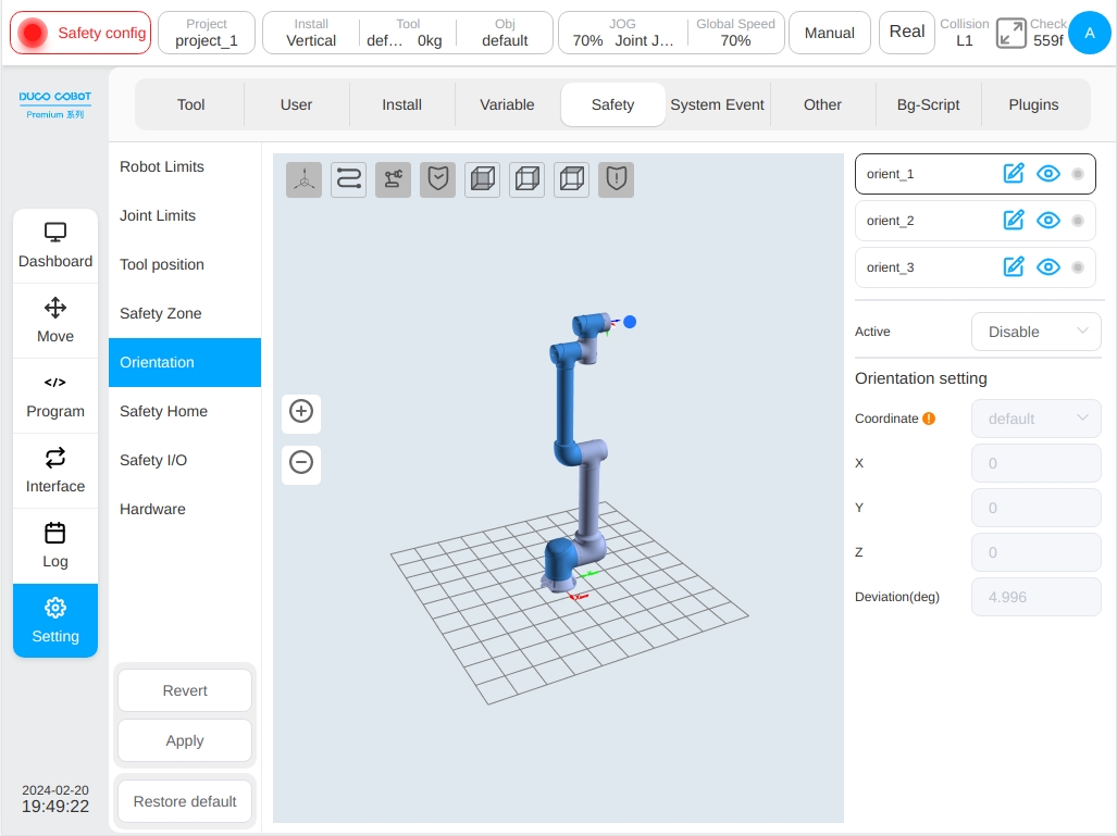
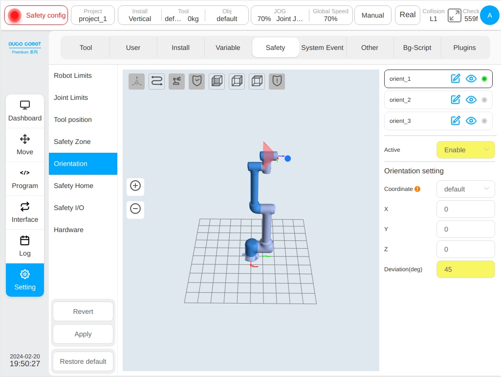
Safety Posture Zone#
The safety posture zone setting. The posture area refers to forming a cone angle around a direction vector in the base coordinate system of the robot. The posture restriction only restricts the Z-axis of the robot TCP to the posture zone. Users can set up to three posture zones. A single posture zone can be shown or hidden by clicking the icon next to the name on the right of the posture area, which is set as default to display. The icon after the name can be clicked to modify the pose zone name. will be displayed if the posture area is not disabled, otherwise will be disabled.
The safety posture zone can be activated in five modes: Disabled, Always active, Automatic mode active, safety Group Configuration 1 and safety group configuration 2. The safety posture zone is different from the safety zone in that only the Z axis direction of TCP is restricted and there is only one response mode that triggers the protective stop after the zone is exceeded.
There are three ways to define a reference coordinate system for the safety posture zone: Custom, capture the current TCP pose and define it through a predefined workpiece coordinate system. When Custom is selected, manually modify the value of the direction vector X, Y, Z, which describes the value in the robot base coordinate system; When the current TCP attitude is selected, the z-axis direction of the current TCP is taken as the reference direction of the posture zone and the direction is converted to the robot base coordinate system to describe the vector direction X, vector direction Y, vector direction Z. If the value is manually modified, it will become a custom mode. When defined by the workpiece coordinate system, the Z-axis direction of the workpiece coordinate system is taken as the reference direction of the posture zone and converted to the robot base coordinate system, the value will be changed into a custom mode after manual modification.
If the orientation of the workpiece coordinate system has been changed externally, a reminder icon is displayed at the reference coordinate system. The zone deviation angle ranges from 5 to 180 degrees. For example:
Safety Home#
For ‘Safety Home’ settings, the ‘Safety Home’ monitoring will synchronize the Home Location settings in the ‘Other’ settings page. If the location in the ‘Safety Home’ settings is different from the Home Location in the ‘Other’ settings, a reminder icon is displayed under ‘Synchronize Home’ settings. If the settings are not synchronized, the Home position of the system is subject to the Safety settings. The settings of the safety controller prevail for the ‘Press Home’ Home point on the mobile interface and the output of home signals from other ports (e.g. port 2001) of the robot. The Home point in the ‘Other’ settings page is only used as a record and does not serve as a basis for judging the Home point. The monitoring threshold of the Home point can be set and the value ranges from 1 to 5°.
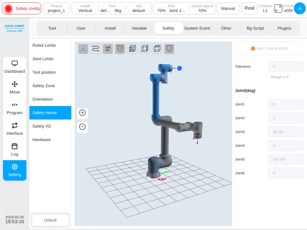
When the synchronize Home location is selected, the joint angle of the Home location is displayed. And the robot model in the 3D model display area is refreshed to the corresponding location.
When the safety home location is set and the home location output is configured in the safety I/O (see Section 6.2.3.8), all joint angles of the robot are within the set home location range (setpoint-threshold, setpoint + threshold) and the speed is close to 0°/s (to filter out normal encoder run-out). The system preset joint speed is less than 2°/s), and lasts for 500 milliseconds (system predefined and cannot be configured), as the signal is reached by the safety output external output home location.
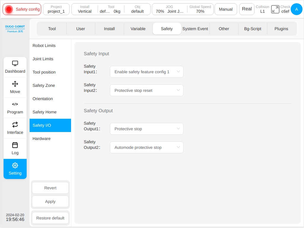
Safety IO#
The safety I/O module contains two configurable safety input ports and two configurable safety output ports.
Safety input features include:
Protective Reset Input:When the protective stop occurs, the port is triggered and the robot returns to normal state.
Automatic Mode Protective Stop Input:After configuration, when robot triggers the port in automatic mode it performs a protective stop.
Automatic Mode Protective Reset Input:When automatic mode protection stop performs, the port is triggered and the robot returns to normal state.
Reduce Mode Input:After configuration, this port is triggered and the robot will transition to reduced mode. The robot will slow down for the parameter limits meet the safety parameter limits in reduced mode.
Safety Combination Configuration 1/2:When safety combination configuration 1 or safety combination configuration 2 port is triggered all safety features configured in safety combination configuration 1 or safety combination configuration 2, including safety tools, safety zones, and safety posture areas, will be activated and monitored.
Safety output features include:
Protective Stop Output:This port is triggered when the robot is in the protective stop state.
Automatic Mode Protective Stop Output:This port is triggered when the robot is in automatic mode protective stop.
Reduce Mode Output:This port is triggered when the robot is in reduce mode.
HOME Location:This port is triggered when the robot is near the safety home location;
Hardware#
Includes external IO enabled for mode switching and three position enable inputs
Enable External IO for Mode Switching:If this item is enabled, manual mode switching can be performed through external IO. The mode switching function on the status bar of the interface is invalid.
Three-position Enable Input:When this is enabled, if the robot is in manual mode, the robot can be moved only when the three-position switch on the teach pendant is in the middle position. When the three-position switch is in the non-middle position at any time during the movement of the robot, the robot will be paused.