Recipe Interface#
Formula classification:
1、According to the function, it is divided into user-defined formula (non-real-time formula) and system data formula (real-time formula) : Custom recipe: The user defines the data format that he wants to receive and send, and the recipe manager extracts the user’s input valid data and frames the output data. The process of receiving and sending is controlled by the user in the script. System data recipe: The user selects the desired data from the system data provided by the system for real-time reading through the output end, or modifies the system variables provided by the robot in real time through the input end. User-configurable variables are provided by the system and cannot be customized for personal use. The receiving and sending of data are not controlled by the user, but by the system in real time. The control period (the fastest period for sending and receiving) is 4ms.
2、According to the protocol, it is divided into streaming protocol formula and can protocol formula: Streaming protocols are formulated for streaming data (485, tcp, etc.) services.
The can protocol formula provides support for can only.
indicates the description of system data mapping#
Data type of recipe:
(1)byte(unsigned 8-bit shaping)
(2)char(signed 8-bit shaping)
(3)word(unsigned 16-bit shaping)
(4)short(signed 16-bit shaping)
(5)dword(unsigned 32-bit shaping)
(6)int(signed 32-bit shaping)
(7)float(32-bit floating point number)
(8)double(64-bit double floating point number)
System data entry:
Data direction: user robot
Formula variable |
type |
Corresponding interface |
Instructions |
|---|---|---|---|
DigitalOutputCommand[1..2] |
byte |
Control cabinet general output DO[1..16 |
The user controls the robot’s DO . A byte sequence corresponds to eight DO’s. |
DigitalOutputCommand[3] |
byte |
End tool output Tool_DO[1..2] |
The first two digits of the byte correspond to tools DO1 and DO2,and the last six digits are reserved. |
BitInputReg[1..2] |
byte |
byte Register function input fun_reg_in[1..16] |
A byte sequence corresponds to 8 register function inputs |
BitInputReg[3..10] |
byte |
byte Register Bool Input bool_reg_in[1..64] |
A byte sequence corresponds to 8 register Bool input |
WordInputReg[1..32] |
word |
Register Word input word_reg_in[1..32] |
Enter 1-32 corresponding registers Word in sequence |
FloatInputReg[1..32] |
float |
float Register Float enter float_reg_in[1..32] |
Enter 1-32 corresponding registers Float in order |
ForceEnd[1..6] |
float |
float End force sensor data |
The force description of the end force sensor data under the robot end TCP. Data definition: X, Y, Z, Rx,Ry,Rz, unit N, Nm |
ForceBase[1..6] |
float |
Base force sensor data |
Force description of the base force sensor data under the robot base. Data definition: X, Y, Z,Rx,Ry,Rz, unit N, Nm |
System data output:
Data direction: robot users
Formula variable |
type |
Corresponding interface |
Instructions |
|---|---|---|---|
DigitalSignalStatus[1..2] |
byte |
Control cabinet general input DI[1..16] |
The robot feedbacks the input signal of the current robot to the user. A byte sequence corresponds to eight DI’s |
DigitalSignalStatus[3] |
byte |
Arm end tool Enter Tool_DI[1..2] |
The first two digits of the byte correspond to DI1 and DI2, and the last six digits are reserved |
DigitalSignalStatus[4..5] |
byte |
Control cabinet general output DO[1..16] |
The robot feedbacks the output signal of the current robot to the user. A byte sequence corresponds to eight DO’s |
DigitalSignalStatus[6] |
byte |
Output Tool_DO [1..2] |
The first two digits of the byte correspond to tools DO1 and DO2, and the last six digits are reserved |
DigitalSignalStatus[7] |
byte |
IO function Input fun_io_in[1..8] |
A byte sequence corresponds to function input 1-8 |
DigitalSignalStatus[8] |
byte |
IO function output fun_io_out [1..8] |
A byte sequence corresponds to 1-8 of the function output |
RobotState[1..7] |
float |
Actual joint position |
6 Actual position of each joint . The seventh position is reserved. Unit is rad |
RobotState[8..13] |
float |
float The actual Cartesian pose with the end in the base coordinate system |
End Cartesian space actual . TCP relative to the base posecoordinate system. Data definition: X,Y,Z,Rx,Ry,Rz, unit m, rad |
RobotState[14..19] |
float |
Cartesian actual moment |
Force description of the end force sensor data under the end flange of the robot. Data definition: X,Y,Z,Rx, Ry,Rz, unit N, Nm |
RobotState[20..25] |
float |
Offset of tool coordinate system |
The pose offset in the tool coordinate system |
RobotState[26..29] |
float |
Load mass and center of mass |
Mass and center of mass of end load, unit kg,m |
RobotState[30..32] |
float |
reserv |
No |
BitOutputReg[1..2] |
byte |
Register function output fun_reg_out[1..16] |
A byte sequence corresponds to the function output of eight registers |
BitOutputReg[3..10] |
byte |
Register Bool Output bool_reg_out[1..64] |
A byte sequence corresponds to 8 register Bool output |
WordOutputReg[1..32] |
word |
Register Word Output word_reg_out[1..32] |
Enter 1-32 corresponding registers Word in sequence |
FloatOutputReg[1..32] |
float |
Register Float output float_reg_out[1..32] |
Enter 1-32 corresponding registers Float in order |
Recipe creation#
streaming data recipe#
User-defined recipe#
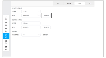
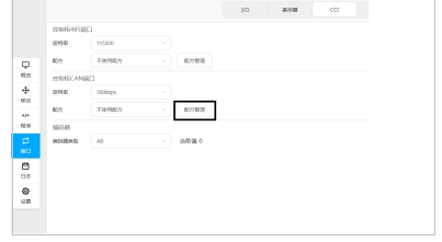
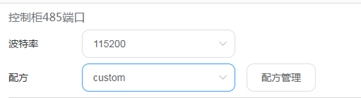
1、Select any streaming port (485, tcp, etc.) formula management in the ui interface (select 485 port here)
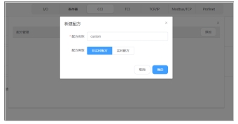
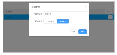
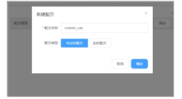
2、Click Add, enter the recipe name, and select the non-real-time recipe
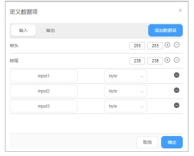
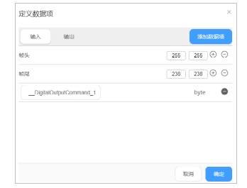
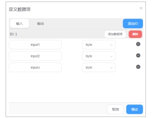
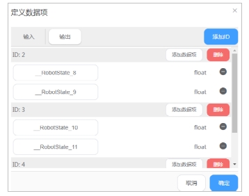
3、Add input data items
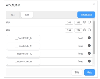
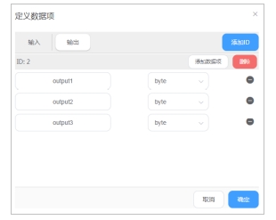
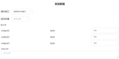
4、Add output data items
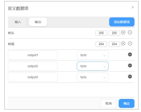
Click OK. Recipe creation is complete. Note: The header and tail of the input and output frames are relatively independent and need to be configured separately without affecting each other.
System data formulation#
1、 Select any streaming port (485, tcp, etc.) formula management in the ui interface (select 485 port here)
2、Click Add, enter the recipe name, and select the non-real-time recipe
3、Add input data items
4、 Add output data items
5、Click OK to complete the recipe creation.
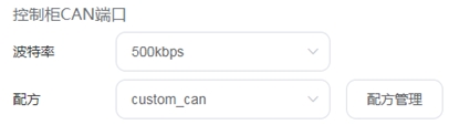
CAN protocol recipe#
User-defined recipe#
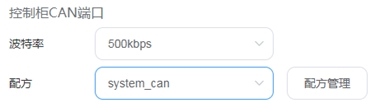
1、Select can port formula management in the ui interface
2、Click Add, enter the recipe name, and select the non-real-time recipe
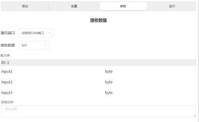
3、Add input data items
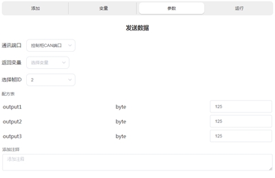
4、 Add output data items
Click OK. Recipe creation is complete.
System data formulation#
1、Select can port formula management in the ui interface
2、 Click Add, enter the recipe name, and select the real-time recipe
3、 Add input data items
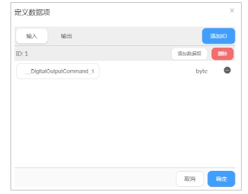
4、 Add output data items
5、Click OK to complete the recipe creation。
Formulation use#
Use of 485 port formula#
Custom recipes to use#
1、use 485 to serial debugging assistant to connect the computer and robot 485 port
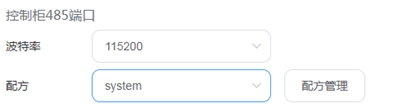
2、Select the recipe file for port 485
3、Write program flow control
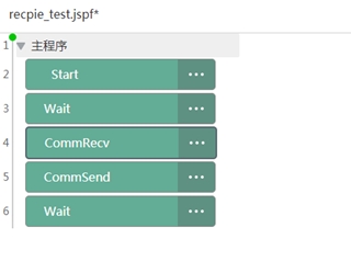
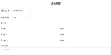
CommRecv:
CommSend:
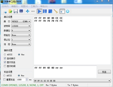
4、run the program, serial debugging assistant send FF FF 01 02 03 EE EE
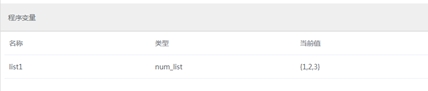
5、program variable interface display
6、In the serial debugging assistant, you will receive: FF FF 7D 7D 7D FE FE
System formulation use#
1、use 485 to serial debugging assistant to connect the computer and robot 485 port
2、Select the recipe file for port 485
3、Due to the selection of real-time system formula, the serial debugging assistant will periodically receive robot pose data:
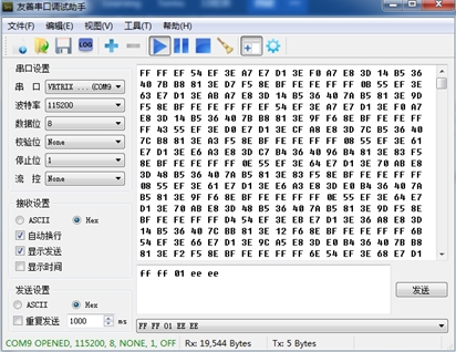
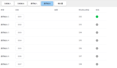
4、when sending FF FF 01 EE EE through the serial debugging assistant, the corresponding IO port will be controlled through the recipe manager
Use of CAN port formula#
Custom recipes to use#
1、Connect the computer with the robot using the can box, and debug the can using CanTest
2、Select recipe file for can port
3、Write program flow control
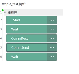
CommRecv:
CommSend:
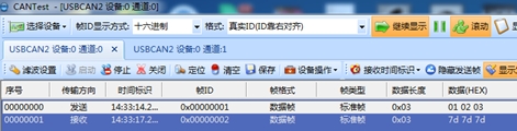
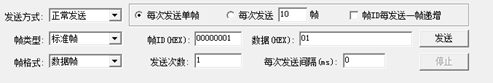
4、Run the program, CanTest send data frame id 1, data 01 02 03
5、program variable interface display
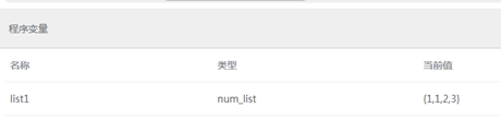
The first variable in the list is the received frame id, followed by the data.
6、The CanTest terminal will receive frame id 1:7D 7D 7D(125 125 125).
System formulation use#
1、Connect the computer with the robot using the can box, and debug the can using CanTest
2、Select recipe file for can port
Due to the selection of a real-time system formula, CanTest will periodically receive robot pose data:
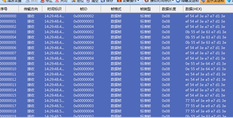
When the data frame id 1 is sent via CanTest and the data is 01, the corresponding IO port will be controlled via the recipe manager:
Use of TCP and UDP port recipes#
The tcp/ip interface can also use the streaming recipe interface; for historical reasons, tcp and udp can only use the system data recipe in the recipe (real-time recipe).
The robot controller provides two ways to use the formula for the tcp/ip interface:
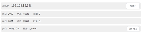
1、udp server, port 2011.
2、tcp/udp client, ip and port are user-defined.
udp server#
1、 Use the network cable to connect the computer and the controller, use the network debugging assistant to test
2、Configure the formula file for the udp server
3、 Use the debugging assistant to create a udp client
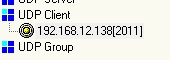
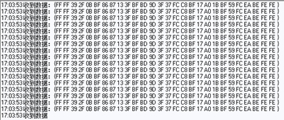
4、 Periodic robot pose data will be received after successful connection
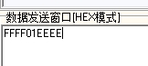
5、 send FF FF 01 EE EE to the server, will control the configuration of the corresponding IO.
tcp/udp client#
1、Use the network cable to connect the computer and the controller, use the network debugging assistant to test
2、Use the debugging assistant to create a tcp/udp server
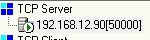
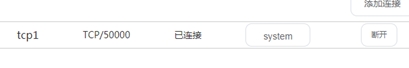
3、Create a tcp/udp client through the ui
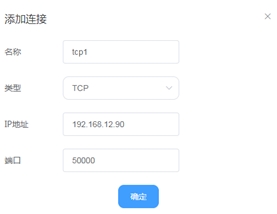
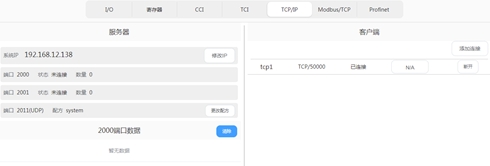
4、Select the recipe file for the client
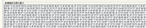
5、The debugging assistant will receive periodic robot pose data
6、Send FF FF 01 EE EE to the client, which will control the corresponding IO of the configuration