Ethernet and IP interface configuration#
Interface description#
Refer to the DUCO CORE Hardware Manual for hardware interface descriptions.
The Ethernet/IP data interaction cycle is 4ms.
script functions#
The robot provides corresponding script functions that can read or write the values of the data interface.
write_reg(number:num,number:type,val)
Function description:
This function modifies the value of the internal register.
Parameter description:
num: indicates the number of an internal register.
type: indicates that the register type 1 is a bool register, 2 is a word register, and 3 is a float register.
val: Specifies the val type based on the type type.
When type is 1, the val type is boolean,true is true, false is false, and num ranges from 1 to 64
When type is 2, the val type is number, the value ranges from 0 to 65535, and the value ranges from 1 to 32
When type is 3, the val type is number and num ranges from 1 to 32
The function does not change the internal register value when the argument is wrong.
Return value:
None
Example:
write_reg( 5, 1,true)
read_reg (number:num,number:type,number:in_out)
Function description:
This function reads the value of the internal register.
Parameter description:
num: internal bool Register number.
type: indicates that the register type 1 is a bool register, 2 is a word register, and 3 is a float register.
When type is 1, num ranges from 1 to 64.
When type is 2, num ranges from 1 to 32.
When type is 3, num ranges from 1 to 32.
The function does not change the internal register value when the argument is wrong.
in_out: 0 indicates that the input register is read, 1 indicates that the output register is read.
Return value:
When type is 1, the return value type is boolean, where true indicates true and false indicates false.
When type is 2, the return value is of type number and ranges from 0 to 65535.
When type is 3, the return value type is number.
Example:
Ret = read_reg,1,1 (10)
Configuration flow#
The following takes Omron PLC as an example to describe the configuration process of Ethernet/IP interface using Sysmac Studio software:
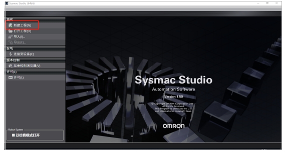
Click New Project:
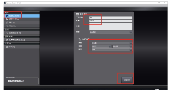
Enter the project name and author, select the model of the current device, and click “Create” :
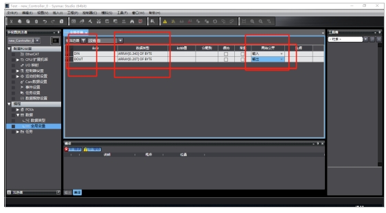
Click on the “Programming” drop-down box and click on “Global Variables”; In the “Global Variables” page, right-click, click “New”, create the variables for receiving and sending (robot→PLC byte size is 344, PLC→robot byte size is 208), and select the variable network exposure type:
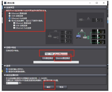
Click “Controller”, “Communication Settings”, select the connection type in the pop-up interface, enter the PLC IP, and click “Ethernet communication test” to check whether the communication between the computer and the PLC is normal:
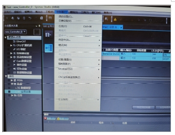
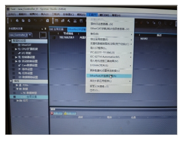
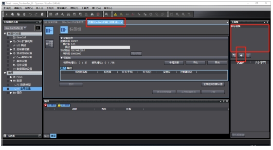
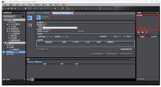
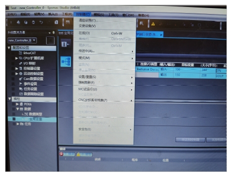
Click “Tools” and “EtherNet/IP Connection Settings (N)” to load the “EtherNet/IP Device List” window:
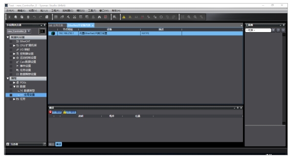
Double-click the item in “EtherNet/IP Device List” to load the “Built-in EtherNet/IP Port Settings Connection Settings” window:
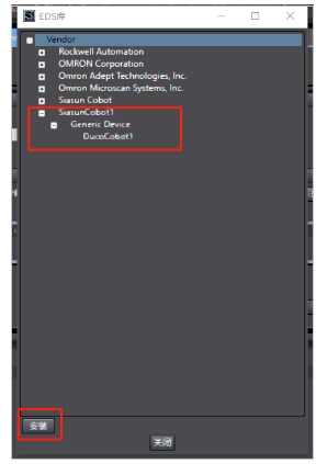
In the “Target Device” window on the right of the software, right-click, click “Show EDS”, the EDS library list pops up, click “Install”, select DUCO COBOT’s EDS file:
Click the + button at the bottom of the Target Device window to add the robot’s IP, select DUCO COBOT’s EDS and select the revised version, then click Add:
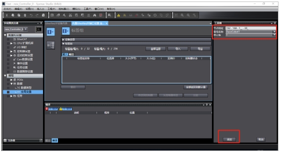
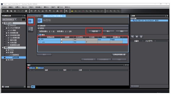
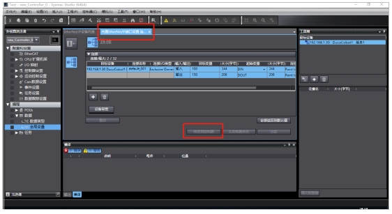
Click the “Register All” button in the “Label Group” window to register the created global variables:
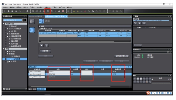
Click the “Connect” icon, then double click the created target device (or left mouse button and long press the target device and drag it to the “Connect” window) to add the robot’s input and output variables to the “Connect” window:
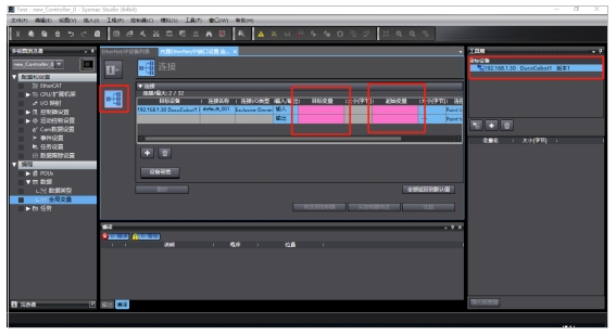
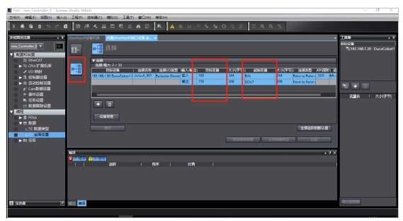
Enter the target variable as “100”, enter the start variable as “DIN” for global variables; Output target variable fill in “150”, output start variable select the global variable output “DOUT” :
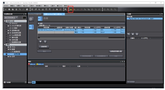
Click on the “Online” icon to connect to the PLC:
After successful connection, click “Controller”, “Sync”, check all options in the pop-up dialog box, and click “Transfer to device” to download EDS to PLC:
Click “Send to Controller” in the “Built-in EtherNet/IP Port Settings Connection Settings” window, select “Edit Mode Transfer” in the pop-up dialog box:
Click “Controller”, “Mode” and select “Run Mode”. Then, click the “Monitoring” icon, load the “Monitoring” window, add input and output variables, monitor (or set) the data received and output by PLC (the received data cannot be modified) :