Maintenance and Repair#
All safety instructions in this manual must be strictly followed for maintenance and repair work.
Maintenance, calibration, repair work should be performed according to the latest service manual.
Safety Instructions#
After maintenance, the safety level of the system must be checked again. Verification must comply with valid standards and safety laws and regulations. All safety functions should also be tested to ensure that they can work properly.
The purpose of maintenance is to ensure the normal operation of the system, or to help the system return to normal operation in the event of a failure. Maintenance includes fault diagnosis and actual maintenance.
Safety measures should be taken during maintenance operations include:
Prerequisites Before maintenance:
The robot must be turned off and have protection measures that can prevent accidental restart.
Remove the main input cable to ensure complete power failure, disconnecting other energy sources. Take precautions to avoid system power reconnection during maintenance.
Check whether the ground connection is good before restarting the system.
Wait 5 minutes until the intermediate loop is fully discharged. Avoid splitting the power supply system in the control cabinet. The high voltage can be retained in the power supply system for several hours after the control cabinet is closed.
Follow ESD standards when disassembling the robot arm or control cabinet.
The pneumatic system is a part of the system independent of the robot and the fixture. After the main power supply of the robot is turned off, the air pressure remains. The robot’s power supply must be cut off and the pressure released before installing or servicing the fixture.
Note:
Do not change any information (such as force limits) in the software security configuration. The security configuration is described in the manual. If safety parameters change, the entire robotic system should be considered new, which means that all safety audit processes, such as risk assessment, which must be updated.
Replace the faulty part with a new part with the same part number or an approved equivalent part.
Reactivate all disabled safety measures as soon as maintenance and repair are complete.
Record all maintenance operations in writing and keep them in the technical documentation associated with the entire robotic system.
Maintenance and Cleaning#
Robot maintenance#
After the commissioning of the equipment, the maintenance work shall be carried out according to the specified maintenance period.
the Robot Maintenance Period Specification Table
No. |
Maintenance Activity |
Inspection Mode |
Every 1Month |
Every 6Months |
Every 12Months |
|---|---|---|---|---|---|
1 |
Check the rear cap and bolt of the robot joint |
Visual i nspection |
√ |
||
2 |
Check the robot dustproof rubber ring |
Visual i nspection |
√ |
||
3 |
Check the cables of the robot |
Visual i nspection |
√ |
||
4 |
Check the mounting bolts of robot base |
F unctional ex amination |
√ |
||
5 |
Check the mounting bolts of robot end tool |
F unctional ex amination |
√ |
||
6 |
Check the mounting bolts of robot joint |
F unctional ex amination |
√ |
||
7 |
Check the seal ring of light belts |
Visual i nspection |
√ |
||
8 |
Check joint gaps for grease spills |
Visual i nspection |
√ |
The figure is an example. In total, there are 6 joints to be examined. It is necessary to regularly check whether the bolt marking is complete, whether the structure is reliable, and whether the grease is spilled.

Figure 1 Robot Structure Diagram
Robot Cleaning#
Dust/dirt/oil observed on the robot arm can be wiped off using a clean cloth and water or 10% ethanol. In some extreme cases, a small amount of grease may spill from the joint, which does not affect the performance or life of the joint.
Robot zero position and positive direction#
After the commissioning of the equipment, the maintenance work shall be carried out according to the specified maintenance period.
the Control System Maintenance Period Specification Table
No. |
Maintenance Activity |
I nspection Mode |
Every 1Month |
Every 6Months |
Every 12Months |
|---|---|---|---|---|---|
1 |
Check emergency stop |
F unctional ex amination |
√ |
||
2 |
Check the three-position enable switch of the teach-pendant |
F unctional ex amination |
√ |
||
3 |
Check control cabinet safety input and output |
F unctional ex amination |
√ |
||
4 |
Check the teach-pendant cables and connectors |
Visual i nspection |
√ |
||
5 |
Check the fan filter of the control cabinet |
Visual i nspection |
√ |
||
6 |
Check the I/O terminal block of the control cabinet |
F unctional ex amination |
√ |
||
7 |
Check the power port of the control cabinet |
F unctional ex amination |
√ |
Note: When used in an environment with humidity greater than 90%, the control cabinet must be connected with the teach-pendant. If you need to pull out the teach-pendant for use, please take necessary protective treatment on the interface of the teach-pendant of the control cabinet.
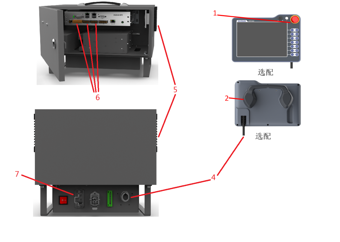
Figure 2 Control System Structure Diagram
Control Cabinet Cleaning#
The control cabinet package contains two fan shields on both sides, and is equipped with IP44 filter screen, which is mainly used for internal heat dissipation of the control cabinet.
Note: Adjust the direction of the fan dust cover for different control cabinets. Otherwise, the IP protection level will be affected.
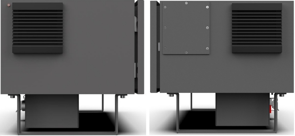
Figure 3 Fan Dust Cover Installed on the Side of the Control Cabinet
Fan filter cleaning procedure:
As shown in Figure 4, there are two gaps in the red box. Insert a small flat-head screwdriver into the gap and pry outward. Remove the dust cover when it becomes loose.
Remove the filter screen, confirm to use low-pressure gas cleaning or directly replace of the filter screen according to the actual situation of the filter screen. The filter screen needs to be cleaned repeatedly on both sides when cleaning to ensure that the filter screen is thoroughly cleaned.
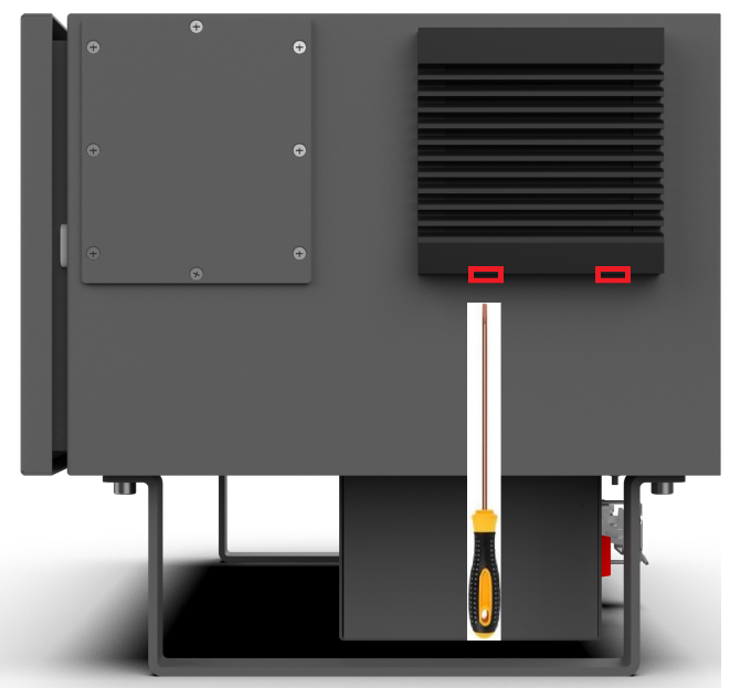
Figure 4 Control Cabinet Screen Cleaning
Operation after Long-term Storage of the Robot#
The robot uses harmonic gear technology, the joints are partially sealed and self-lubricating (no need to change or add grease during its service life). During normal operation, lubricating grease is naturally distributed around gears and bearings to maintain normal lubrication of the mechanical system.
When the robot is stored or stopped for more than 1 month, or the joint is in a very small range of motion for a long time, it is recommended to take the following measures periodically, which will benefit the service life of the robot.
Before switching on the power supply, please put the robot at room temperature (such as stored in a cold environment);
Switch on the power supply of the robot and keep it in a static state for 30 minutes, which will enable the robot to reach its internal working temperature and soften the grease;
In manual mode, slowly move all joints respectively. Take care not to load any payload and tools;
Create a program to move all joints slowly and continuously for at least 20 minutes (default acceleration is recommended, the velocity is set around 10°/s, and the joints are rotated as far as possible).