Belt Tracking Parameter configuration#
Parameter configuration#
Robot belt tracking parameter configuration includes belt type selection, encoder enabled or not, belt speed/encoder coefficient configuration, belt base coordinate system configuration and relevant point teaching, limit tracking distance configuration, select trigger IO configuration, trigger delay/configuration specific interface can be referred to the following figure.

Configuration flow#
The following takes the uniform speed linear conveyor belt as an example to briefly describe the conveyor belt tracking configuration process:
Start the robot controller, start the UI, and click “Program” at the first place in the new program view to enter the program interface. If there is currently no user conveyor belt tracking program, click “New program” at the second place, manually enter the program name test_line_conveyor, and click “Confirm” to complete the program creation. If you need to open the existing conveyor belt tracking program, you can select the program and double-click to enter the program, and modify the parameters of the conveyor belt instruction. Opening the existing program mainly involves modifying the parameters and points of the conveyor belt instruction in the program, and its operation can be covered in the operation of the new program. The following is mainly to take the operation of the new program as an example to explain the operation of the conveyor belt:
New program view

After entering the test_line_conveyor.jspf program, click the select point button (1 place) in the following figure, and the UI interface will enter the moving interface. By moving the robot to the specified position through joints (2 places) or pose (3 places), click the record current joint button (4 places) to record the current point. After success, the UI interface will return to the program interface, and the current node of the robot will be displayed in 5 places, and the user can adjust the joint angular speed according to the actual situation.

After teaching the starting point, you can add the Conveyor belt main program (Conveyor) by clicking the Add button (at 1), selecting the extension (at 2) and clicking, dragging the conveyor instruction (at 3) to the program tree (at 4), and finally clicking the Save program button (at 5) to save the program. At this point, the main program of the conveyor belt is added, and then the main program parameters of the conveyor belt need to be configured.

Click the Conveyor instruction (1) in the program tree, click the parameter (2), select the conveyor belt type (3), the conveyor belt type supports linear conveyor belt and circular conveyor belt, select whether to enable the encoder (4), if the encoder is enabled, the encoder coefficient needs to be provided. Encoder coefficient can be selected for teaching or direct input. If the user has previously calibrated the conveyor encoder, you can directly enter the encoder coefficient, otherwise choose to teach. If the encoder is not enabled, the user needs to enter the speed of the conveyor belt. In this example, the conveyor type is set to straight line, and the encoder is enabled. The encoder coefficient is obtained by teaching.

Next, it is necessary to teach the coordinate system of the conveyor belt base. In the parameter interface and in the robot base coordinate system, teach the position of P1 point (1), P2 point (2) and P3 point (3) in turn, and finally click the calibration button (4). If the calibration is successful, the system will calculate the conveyor belt base coordinate system according to the teaching point and display it (5). Finally, click Add to the system (6) and input the name of conveyor belt base coordinate system ConvBase. Users can modify it according to their own habits and add the conveyor belt base coordinate system ConvBase to the system. This example is illustrated with ConvBase. Thus, the calibration of the coordinate system of the conveyor belt base is completed. The point selection of P1, P2 and P3 will be introduced in detail in the following chapters.

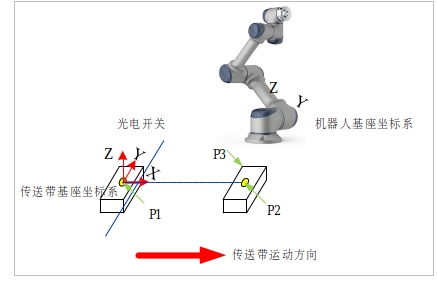
For the selection of P1, P2 and P3 points of the linear conveyor belt, it should be noted that the position of P1 point is the position of the coordinate system of the conveyor belt base, that is, the workpiece just triggers the photoelectric switch signal, and the position of the marked point on the workpiece is in the robot base coordinate system. If a vision system is used, the vision system shall be configured with reference to the corresponding vision application description. A program shall be written to obtain the calibration value of the workpiece relative to the conveyor belt base coordinate system at the trigger time from the vision system. Calibration shall ensure that the calibration value of the workpiece coordinate system obtained by the vision system is accurate relative to the conveyor belt base coordinate system. And the robot controller can obtain the calculated calibration value of the vision system in time. Point P2 is the position of the mark point on the workpiece in the robot base coordinate system after the workpiece follows the conveyor belt for a distance. In the working range of the robot and the conveyor belt, the movement distance of the conveyor belt should be as large as possible, which is conducive to the accuracy of the calibration results. The P3 point is the arbitrarily selected point in the parallel plane between the workpiece marking point and the conveyor belt. The coordinate system calibration diagram of the linear conveyor belt base is as follows:
For the arc conveyor belt: the position of P1 point is the position of the conveyor belt base coordinate system, that is, the workpiece just triggers the photoelectric switch signal, and the position of the marked point on the workpiece is in the robot base coordinate system. If a vision system is used, the vision system shall be configured with reference to the corresponding vision application description. A program shall be written to obtain the calibration value of the workpiece relative to the conveyor belt base coordinate system at the trigger time from the vision system. Calibration shall ensure that the calibration value of the workpiece coordinate system obtained by the vision system is accurate relative to the conveyor belt base coordinate system. And the robot controller can obtain the calculated calibration value of the vision system in time. Point P2 is the position of the mark point on the workpiece in the robot base coordinate system after the workpiece follows the conveyor belt for a distance. In the working range of the robot and the conveyor belt, the movement distance of the conveyor belt should be as large as possible, which is conducive to the accuracy of the calibration results. Point P3 is the position of the marked point on the workpiece in the base coordinate system of the robot after the workpiece continues to follow the conveyor belt for a distance after point P2. The calibration diagram of circular belt base coordinate system is as follows:

At the bottom of the parameter interface, the user can set the limit tracking distance, that is, the maximum tracking distance of the robot (1 place). When the tracking distance exceeds the limit tracking distance, the robot will report an error and abandon the current tracking target. Select trigger IO (2), which can be set by the user according to the actual IO configuration, which is used to notify the robot that the current target has passed the conveyor base coordinate system and can be ready for tracking. The trigger delay (3 places) is used to set how long or long distance the current robot will start tracking after passing through the conveyor base coordinate system. When all parameters are configured, click the OK button (at 4), and then click Save program (at 5) to complete the whole process of belt parameter configuration.

Once the parameters are configured, the conveyor tracker can be edited.