External ports on the control cabinet#
The external interface diagram and interface description of the control cabinet are shown in Figure 2 and Figure 3:
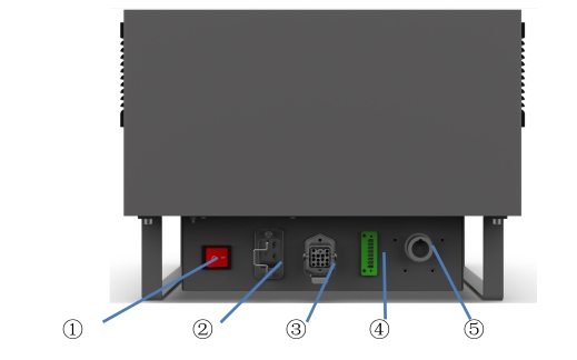
Figure 3 Bottom port of control cabinet
1 – System switch
2 – AC input port
3 – robot port
4 – teach pendant shielding port
5 – teach pendant port
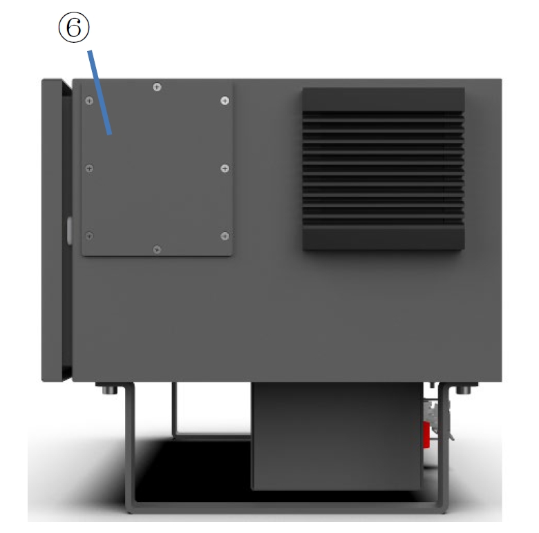
Figure 4 Side port of control cabinet
6 – Component expansion board
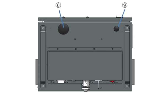
Figure 5 Ports at the bottom of the control cabinet
8 – reserved hole 1
9 – Reserved hole 2
AC input#
DC15S control cabinet power supply input: 100-240VAC, 47-63HZ, 10A;
DC30D control cabinet power supply input: 200-240VAC, 47-63HZ, 10A;
100-200VAC, 47-63HZ, 16A.
System switch#
The system switch is used to turn on and off the power of the control cabinet to realize the power function of the whole system. The system is powered on in the “powered on” state, press the power on button to start the operation in this state, and the system is powered on normally. In the “◎” state, the system is disconnected from the power supply, the system is in the power off state, no power supply input, the system cannot start (note: if the AC input is not disconnected, the incoming line end is in the live state at this time, do not touch).
The power-on sequence of the robot system is: turn on the AC input in the control cabinet and supply power → press the system switch to “colorful” → press the power-on button → Power on the system → Power on the robot; The system power-off sequence is as follows: The UI of teach pendant robot is powered off (the robot is powered off) → The system is powered off on teach pendant interface → Press the system switch to the “◎” state → Disconnect the AC input of the control cabinet.
Robot port#
The robot port definition of DC15S&DC30D control cabinet is shown in Table 2:
Table 2 Definition of robot port of DC15S&DSC30D control cabinet

Connector Number |
Signal Definition |
Remark |
9 |
48V |
|
10 |
48V |
|
11 |
0V |
|
12 |
0V |
|
PE |
PE |
|
1 |
EtherCAT Tx+ |
|
2 |
EtherCAT Tx- |
|
3 |
EtherCAT Rx+ |
|
4 |
EtherCAT Rx- |
Teach pendant shielding port#
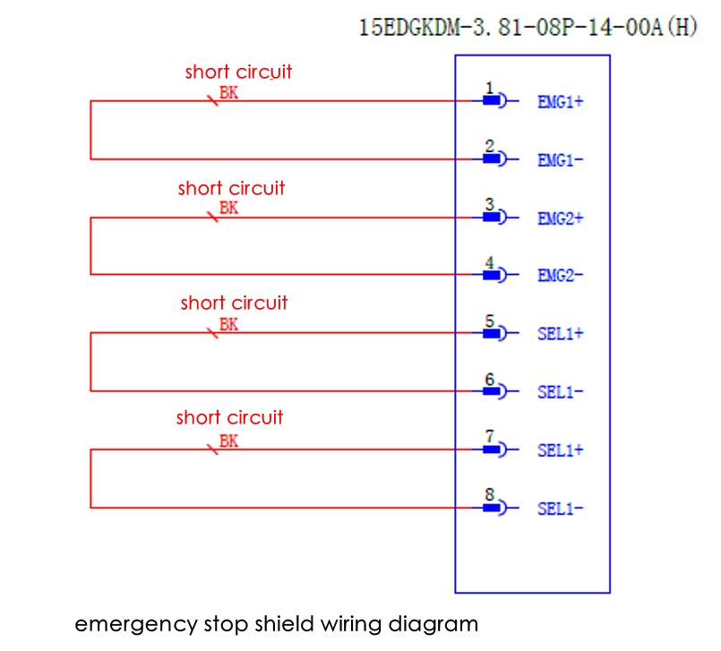
The shielding port of teach pendant in the control cabinet is used for robot mode switching, emergency stop function or emergency stop shorting function after unplugging teach pendant.
The definition of the shielding port of teach pendant in the control cabinet is shown in Table 3:
Table 3 shows the shielding port of teach pendant

Connector Number |
Signal Definition |
Remark |
1 |
EMG1+ |
(TP emergency-stop input 1+) |
2 |
EMG1- |
(TP emergency-stop input 1-) |
3 |
EMG2+ |
(TP emergency-stop input 2+) |
4 |
EMG2- |
(TP emergency-stop input 2+ |
5 |
SEL1+ |
(Mode switching input 1+) |
6 |
SEL1- |
(Mode switching input 1-) |
7 |
SEL2+ |
(Mode switching input 2+) |
8 |
SEL2- |
(Mode switching input 2-) |
Application examples:#
a) In situations where a single teaching pendant is used in many control cabinets: After debugging is completed, adjust the robot to the “automatic operation” state. Please insert the emergency stop button wire according to the following diagram or short-circuit wiring (short circuit emergency stop and mode switching) according to the following diagram ; Attention: When the emergency stop shield is short circuited, the teaching pendant’s emergency stop will fail. Please ensure that the robot system has been configured with other external emergency stops according to safety requirements, or that the emergency stop harness (standard 5m) has been selected according to requirements.
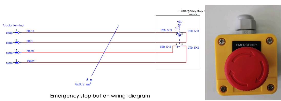
Insert the above wire harness or short circuit plug into the shielding interface, unplug the teaching pendant, and it will not affect the operation status of the robot at this time;
c) When the robot is running automatically and needs to insert the teaching pendant again for manual operation, first turn the teaching pendant mode selection switch to automatic mode, then insert the teaching pendant into the teaching pendant interface of the control cabinet, and then unplug the wiring harness or short circuit plug. Next, the robot can be manually operated through the teaching pendant. Attention: Except for the situation of insertion and removal of the teaching pendant, where the short circuit plug and the teaching pendant are connected to the control cabinet at the same time. It is not allowed to connect both the short circuit plug and the teaching pendant to the control cabinet at any other time. d) The software mode switching function also can be set to take effect through the software interface to block the hardware mode switching function interface. After shield, the hardware of the teaching pendant mode switching interface will no longer take effect, and there is no need to short circuit the plug-in when plugging or unplugging the teaching pendant; e) This interface is prohibited for applications where one teaching pendant is paired with one control cabinet.
Teach pendant port#
Table 4 shows the port of the robot teach pendant. Please refer to the specification list for the selection of teach pendant type. The internal wiring harness port is defined as follows:
Table 4 shows teach pendant port definition
DC00 TP port |
Corresponding TP junction box port |
VGACOM3/COM4 |
VGA |
COM0/COM1(KEY/TOUCH) |

Teach pendant junction box power port#
Table 5 shows the power port of teach pendant junction box:
Table 5 shows the power port of teach pendant junction box

Connector Number |
Signal Definition |
Remark |
1 |
DC24V |
|
2 |
0V |
|
3 |
FG |
Teach pendant terminal box IO port 1#
Table 6 shows the IO port 1 port of teach pendant junction box:
Table 6 shows IO port 1 of teach pendant junction box

Connector Number |
Signal Definition |
Remark |
1 |
EMG2- |
Emergency-Stop Signal |
2 |
EMG1- |
|
3 |
EMG2+ |
|
4 |
EMG1+ |
|
5 |
PUSH- |
Button signal with light |
6 |
PUSH+ |
Teach pendant terminal box IO port 2#
Table 7 shows the IO port 2 port of teach pendant junction box:
Table 7 shows IO port 2 of teach pendant junction box

Connector Number |
Signal Definition |
Remark |
1 |
EN2- |
Three-position switch signal (Enable signal) |
2 |
EN2+ |
|
3 |
EN1- |
|
4 |
EN1+ |
|
5 |
SEL2- |
Key switch signal(Mode
|
6 |
SEL2+ |
|
7 |
SEL1- |
|
8 |
SEL1+ |
COM0 and COM1 ports of the terminal box of teach pendant#
This port is a standard 9-pin D-type base; Table 8 shows the COM0/COM1 port of the teach pendant junction box:
Table 8 shows teach pendant junction box COM0/COM1

Connector Number |
Signal Definition |
COM0[RS-232] |
COM1[RS-232] |
1 |
TXD0 |
RS232 TXD |
|
2 |
TXD1 |
RS232 TXD |
|
3 |
GND |
Ground |
|
4 |
RXD0 |
RS232 RXD |
|
5 |
RXD1 |
RS232 RXD |
|
6 |
NC |
No connection |
|
7 |
NC |
No connection |
|
8 |
NC |
No connection |
|
9 |
NC |
No connection |
|
VGA port of teach pendant terminal box#
This port is a standard VGA port with a standard 15-pin D-type female base
Component extension edition#
If a component such as a switching power supply needs to be expanded, remove the expansion board and install a guideway component.
Reserve holes 1 and 2#
The reserved hole 1 is a round hole with a diameter of 18 Reserve hole 2 is a round hole with a diameter of 40 When digital IO, safety IO, remote switch and other functions need to be used, the external wiring harness can be connected to the control cabinet through the reserved hole; Cover removal method: Squeeze the buckle of the cover to the center of the circle as shown in the figure, and then push it outward to remove the cover.