DC00-J9 Controller (Independent instructions)#
Basic parameter#
DC00 Controller specifications
Use requirement#
When using the robot and DC00 control cabinet, the user must follow the recommended electrical parameters to reach or exceed the limit parameters, which may cause damage to the controller hardware.
Power supply requirement#
The DC00 control cabinet needs two sets of external power supplies, DC24V and DC48V, which are isolated from each other and not grounded together.
Voltage range |
Minimum |
Maximum |
|---|---|---|
DC48V |
45V |
59.2V |
DC24V |
22V |
26V |
DC24V supplies power to the teaching pendant, RC controller, fan, EIO (function extension IO), and the control circuit itself. The GND of DC24V and PE (shell) are shorted together on the RC control board. DC48V is supplies to the robot by controller board. DC48V convert to 24V, it supplies internal IO power. IO-POWER supplies SIO (safety IO), DIO (digital IO), and CIO (configurable IO) interface power. And, the ground of DC48V and 24V is not connected to PE (shell), which is defined as 0V in this manual. The electrical logic of power management is shown in the following figure: black represents the 0V of DC48V and 24V, and blue represents the GND of DC24V connected to the PE casing.
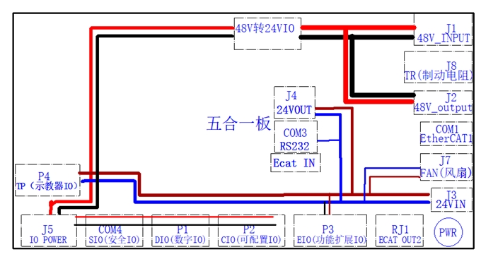
Attention: The ground or negative pole of the equipment connected to SIO (safety IO), DIO (digital IO), and CIO (configurable IO) should be isolated from the conductive part of the casing; If connected to the conductive part of the body shell, it cannot be connected to the system body’s shell (PE).
The recommended peak power supply with the GCR series robot is as follows:
No |
Robot Specification |
Control Cabinet |
|---|---|---|
1 |
GCR3 |
900W |
2 |
GCR5、GCR7 |
1800W |
3 |
GCR10、GCR12、GCR16 |
2100W |
4 |
GCR16-2000、GCR14 GCR20、GCR25、GCR30 |
3000W |
Installation requirements#
You can use the DC00 controller sealing assembly _ Angle iron (recommended number 4) as required. Remove the M3 screws on the controller shell as shown in the figure and install the Angle iron. Then use the M3 screws (provided by the customer) to safety the controller through the reserved holes in the Angle iron to the required length. The reference size of the bottom assembly is shown in Figure 23:
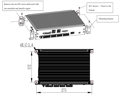
Figure 23 DC00 controller installation dimensions
The DC00 control cabinet shall be installed in a dry place with good ventilation, and the DC00 control cabinet shall be cooled by natural convection. When the use scenario is to generate a large amount of heat, such as the robot body running fast, heavy load or frequent braking, the DC00 control cabinet needs to be cooled by an external fan. In order to ensure cooling by fans and natural convection, please refer to the following figure for installation, ensure that each DC00 control cabinet spacing of more than 100mm (heat dissipation requirements) reserved between the vertical side spacing of more than 50mm, as shown in Figure 24.
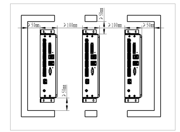
Figure 24 DC00 control cabinet installation spacing
Switch on and off#
The DC00 control cabinet supports a variety of switching modes, which can be used as follows:
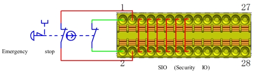
Emergency stop#
The emergency stop button is connected to the safety I/O port. For details, see 5.9.1 SIO Port Wiring Diagram (b).