


process library#
Click “Process Library” in the navigation bar to enter the process library page, the default into the single process list sub-page, as shown in the figure below.
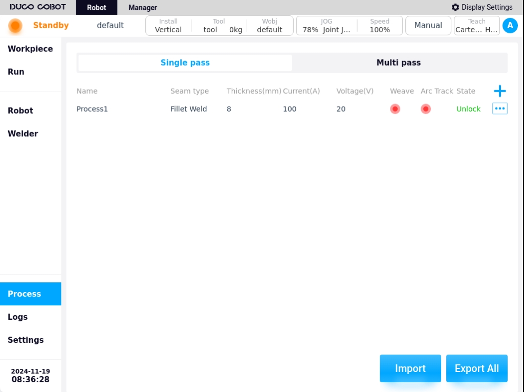
The Process Library page is used to manage all process files within the currently active project. There are two types of processes: single-pass and multi-pass. The process list mainly displays the process name, weld type/bevel type, plate thickness, welding current, welding voltage, whether pendulum welding is enabled or not, whether arc tracking is enabled or not, file status, and process file operation icons and buttons.and process file operation icons and buttons. The weld type is displayed for single-pass processes and the bevel type is displayed for multi-layer multi-pass processes; The unit of welding current is A, the unit of welding voltage is V. The file status includes open and locked.
Single-pass process#
In the Single Process List sub-page, click the icon  to bring up the keyboard and generate the process name “Process X” by default, as shown in the following figure.

The process name can also be customized by the user. If you don’t need to modify it, select the default process name and click the “OK” button on the keyboard.Enter the process editing page as shown below.

The process parameter editing page contains the following sections: seam type, plate thickness, welding parameters, motion parameters, arc start parameters, arc finish parameters, burnback parameters, pendulum welding settings, and arc tracking settings.
Types of welds: The types of single-pass welds are fillet welds, butt welds, and lap welds;
Plate thickness: Thickness of the weldment plate;
Welding parameters
Welding mode: used to set the working mode of the welding torch, including: constant voltage mode, pulse mode, JOB mode and low spatter mode four;
Independent/Unitary Mode: Independent mode is that the welding current and voltage are given separately; Unitary mode is that the welding voltage is automatically matched by the welder according to the current, and the adjustment size of the voltage can be specified;
Note
NOTE: For the Otto welder, set the
Welding current: the value of current in the welding process, in A;
Welding voltage: the value of voltage in the welding process, in V;
Movement parameters
Welding speed: the speed at which the torch runs during the welding process;
Non-welding section speed: torch running speed during non-welding process;
Runaway multiplier: the multiplier of the welding speed without turning on the welding enable;
Arc initiation parameters
Welding Mode: Used to set the working mode of the arc starting stage of the welding torch, including: constant voltage mode, pulse mode, JOB mode and low spatter mode four;
Independent / one-dimensional mode: independent mode is the welding current and voltage are given separately; one-dimensional mode is the welding voltage is automatically matched by the welder according to the current, you can specify the size of the voltage adjustment;
Note
NOTE: For the Otto welder, set the
Arc current: the value of welding current in the arc starting stage, in A. Arc voltage: the value of welding voltage in the arc starting stage, in V;
Arc voltage: the value of welding voltage at the arc starting stage, in V;
Pre-feeding time: the time to start sending shielding gas before starting the arc, in ms.
Arc start time: the time to use the arc start parameter to weld after the arc start is successful;
Arc start pause time: the time that the robot stays in place at the arc start point after the arc start is successful;
Arc detection time: the maximum detection time from sending the arc command to the arc generated. If the arc is not detected within this time. The arc will be started again according to the “Arc Repeat Count”;
Arc Repeat Times: the number of times the arc is restarted after detecting no arc.
Arc closing parameters
Welding mode: used to set the working mode of the arc closing stage of the welding torch, including: constant voltage mode, pulse mode, JOB mode and low spatter mode four;
Independent / one-dimensional mode: independent mode is the welding current and voltage are given separately; one-dimensional mode is the welding voltage is automatically matched by the welder according to the current, you can specify the size of the voltage adjustment;
Note
NOTE: For the Otto welder, set the
Arc closing current: the value of welding current in A during arc closing stage;
Arc closing voltage: the value of welding voltage at the arc closing stage, in V;
Delayed gas feeding time: the time of delayed stopping and gas feeding after the completion of all welding work;
Arc closing time: the time after the start of arc closing to arc closing parameters welding;
Arc closing pause time: the time that the robot stays in place at the arc closing point after arc closing;
Drawback time: the time to draw back the welding wire after arc closing;
Arc recovery and arc restart: when this function is enabled, the arc will be restarted again after arc recovery to fill the arc crater, when enabled, you can define the delay time and arc start time
Burnback parameters
Burnback Parameter Enable Button: used to enable or disable burnback;
Burnback time: burnback time of the burnback parameter;
Pendulum welding setup
Pendulum Welding Setting Enable Button: Used to enable or disable pendulum welding;
Pendulum Welding Type: There are 5 types of pendulum welding types: Triangle, Sine, Arc, Trapezoid, and ‘8’;
Reference Plane: the plane of reference for the pendulum welding process can be selected as: Tool XOY, Tool XOZ, Tool YOZ, Workpiece XOY, Workpiece XOZ, Workpiece YOZ;
Oscillation frequency: set the frequency of the pendulum welding process, unit HZ;
Oscillation amplitude: set the amplitude in the oscillation welding process, unit m;
Left dwell time: only when the pendulum welding mode is selected as sinusoidal or trapezoidal, the parameter needs to be configured, the unit is ms;
Right dwell time: a parameter to be configured only when the pendulum welding mode is selected as sinusoidal or trapezoidal, the unit is ms;
Main path synchronization stay: only when the welding mode is sinusoidal or trapezoidal, the parameter needs to be configured, the default is unchecked; when the parameter is checked, the main path of the robot movement can be stopped at the same time during the left and right stay process;
Arc tracking setup
Arc Trace Enable button: used to enable or disable arc tracing;
Type: the way of arc tracking, options are end clearing path information, end retaining path information, use recorded path information;
Compensation direction: set the compensation direction of arc tracking, optional Y direction or Z direction, i.e. left-right direction or up-down direction;
Reference current (A): arc tracking reference current data value, unit A, default value is 20;
Maximum compensation distance limit Y (mm): maximum compensation distance value in Y direction, unit mm, default value 100;
Maximum compensation distance limit Z (mm): maximum compensation distance value in Z direction, unit mm, default value 100;
Cycle queue coefficient: data acquisition length coefficient,K swing cycles without tracking, unit is times, default value is 2;
Lag time: current feedback data lag time, different welder, different lag time, unit ms, default value 165;
Tracking start time: delay tracking time, to avoid current instability at the beginning of the arc start stage, affecting the tracking effect, the unit is ms, the default value is 2000;
Y-direction sensitivity coefficient: adjust the parameter of Y-direction deskewing ability, the default value is 0.5, and the recommended sensitivity coefficient setting is 0.3-1.0;
Z-direction sensitivity coefficient: the parameter to adjust the ability of Z-direction deviation correction, the default value is 0.5, and the recommended sensitivity coefficient setting is 0.3-1.0;
Current Difference Constant: the default value is 12, the constant used for tracking algorithm, the default is 12 when the wire diameter is 1.2mm;
Current Difference Setting Value: the default value is 2, used for current difference in the set value range without corrective action;
After setting the process parameters, click the “Save” button in the lower right corner of the editing page to return to the process list page, as shown in the figure below.

Click the operation icon  for any process in the process list, and the popup window is displayed as follows.

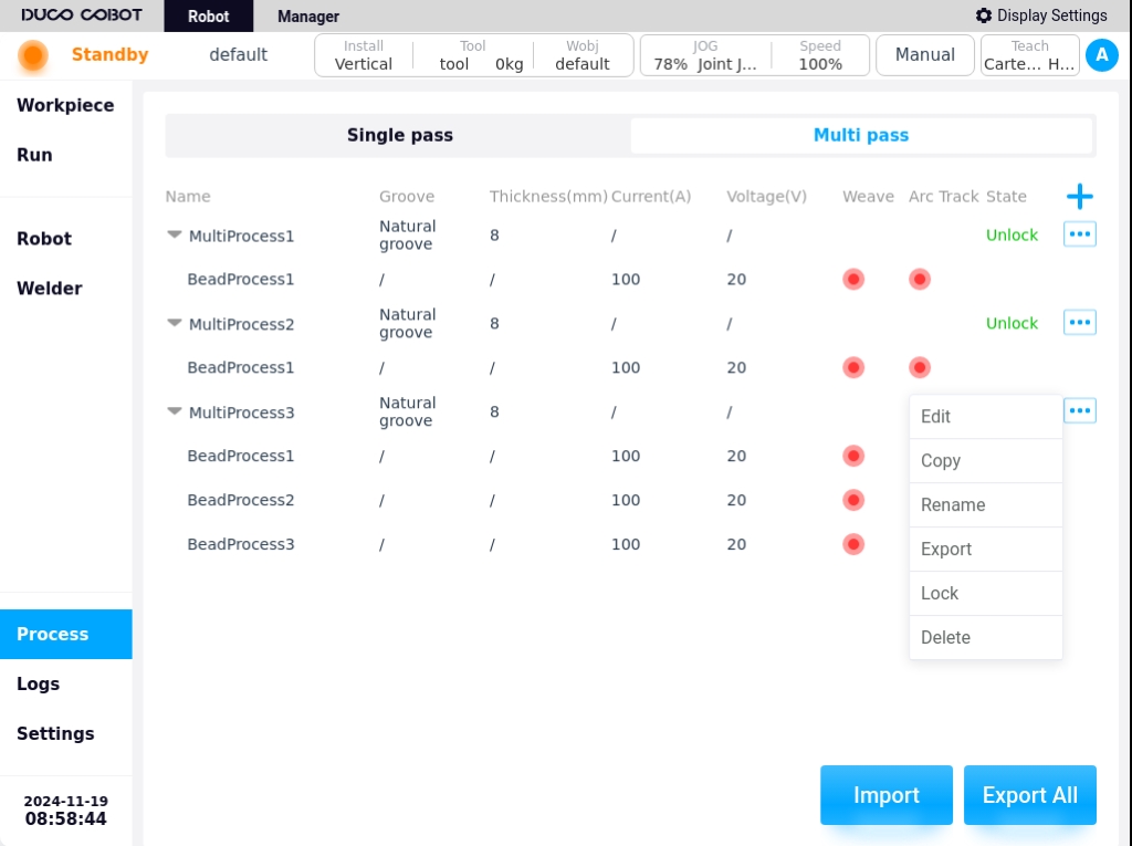
Process operating functions:
Export: Click “Export” to export the process file to USB flash drive.
Copy: Click “Copy” to bring up the keyboard, the process name to be copied will be suffixed with “_copyxx” by default, as shown in the figure below. Users can also modify and rename the process file according to the naming rules.

Click the keyboard “OK” button to copy successfully, the display is as follows.

Rename: Clicking “Rename” will bring up the keyboard, enter the new process name and then OK to modify.
Edit: Clicking “Edit” will enter the parameter editing page of the selected process file, and you can edit its parameters.
Lock/Open: You can lock or open the process file.
Note
Note: This action is only available in advanced mode
Delete: Clicking “Delete” will bring up a confirmation dialog box, and the process file can be deleted after confirmation.
Note
Note: Locked crafts cannot be deleted
Multi-pass process#
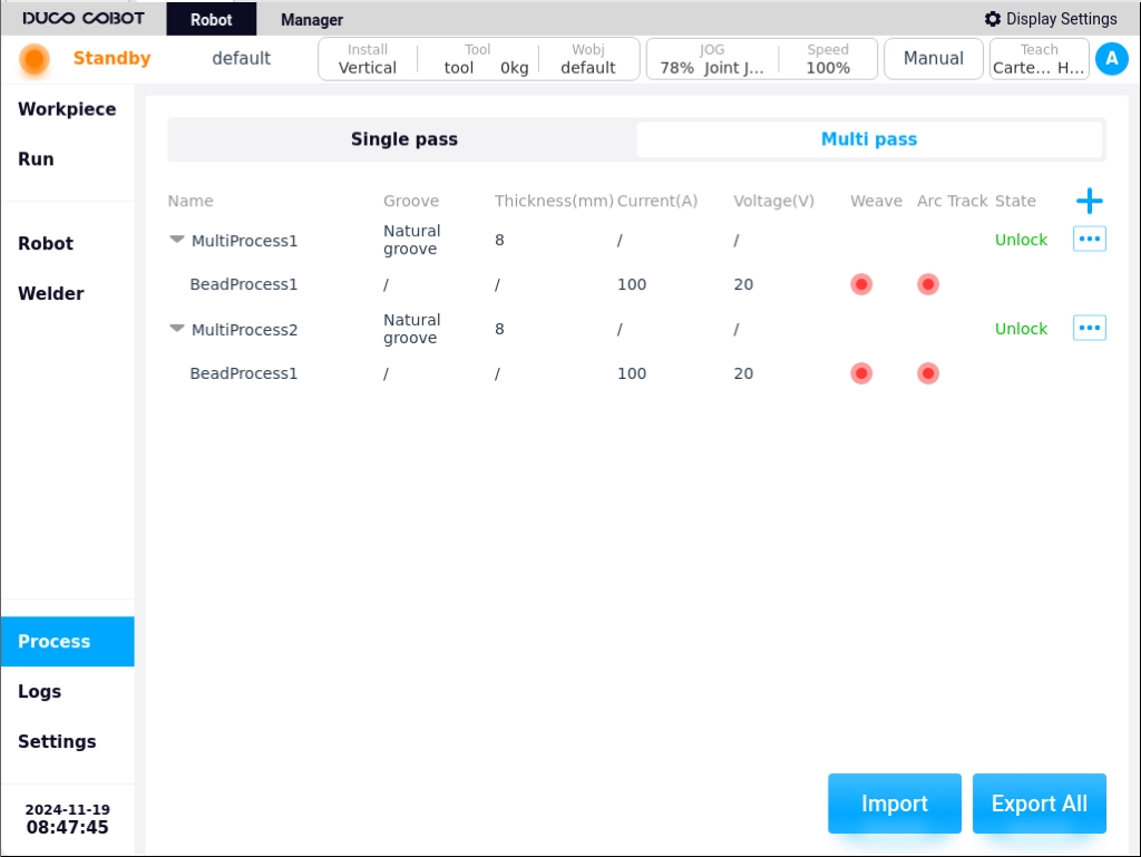
Click the “Multi pass” tab at the top of the Process Library page to enter the Multi-layer Multi-channel process list sub-page, as shown in the following figure.

A multi-pass process is a combination of processes containing multiple weld passes and is created in the process list as a combination process. A multi-layer multi-pass process is a combination of multiple weld pass processes.Click on the icon  to expand the multiple weld passes contained in a multi-layer multi-pass process, and click on the icon
  to collapse it, as shown in the following figure.
Click the icon to bring up the keyboard and generate the process name “Multi-layer Multi-pass Process X” by default, as shown in the following figure.

Similarly, the process name can be customized by the user. If you don’t need to modify it, select the process name generated by default and click “OK” button on the keyboard. Enter the process editing page as shown below.

The types of process parameters on the Multi-Layer Multi-Pass Process Edit page are the same as those for the Single-Pass Process, and will not be repeated here. The difference is that the multi-layer multi-pass process needs to be configured with bevel types.
There are seven types of bevels to choose from: natural, single V, V-type, steep-edge bevel, U-type bevel, single steep-edge bevel, and J-type bevel.
Click the icon at the top of the page to add a new weld process, the weld process name is generated by default “weld process x”, the process parameters are the same as above, as shown in the figure below.

Users can add multiple weld passes sequentially by using the icon, and can switch to different weld passes by using the  and
and  icons to edit the process parameters of the corresponding weld passes.
After editing the process parameters, click “Save” button to return to the process list page. Users can also delete a process by clicking the “Delete” button on the process editing page.
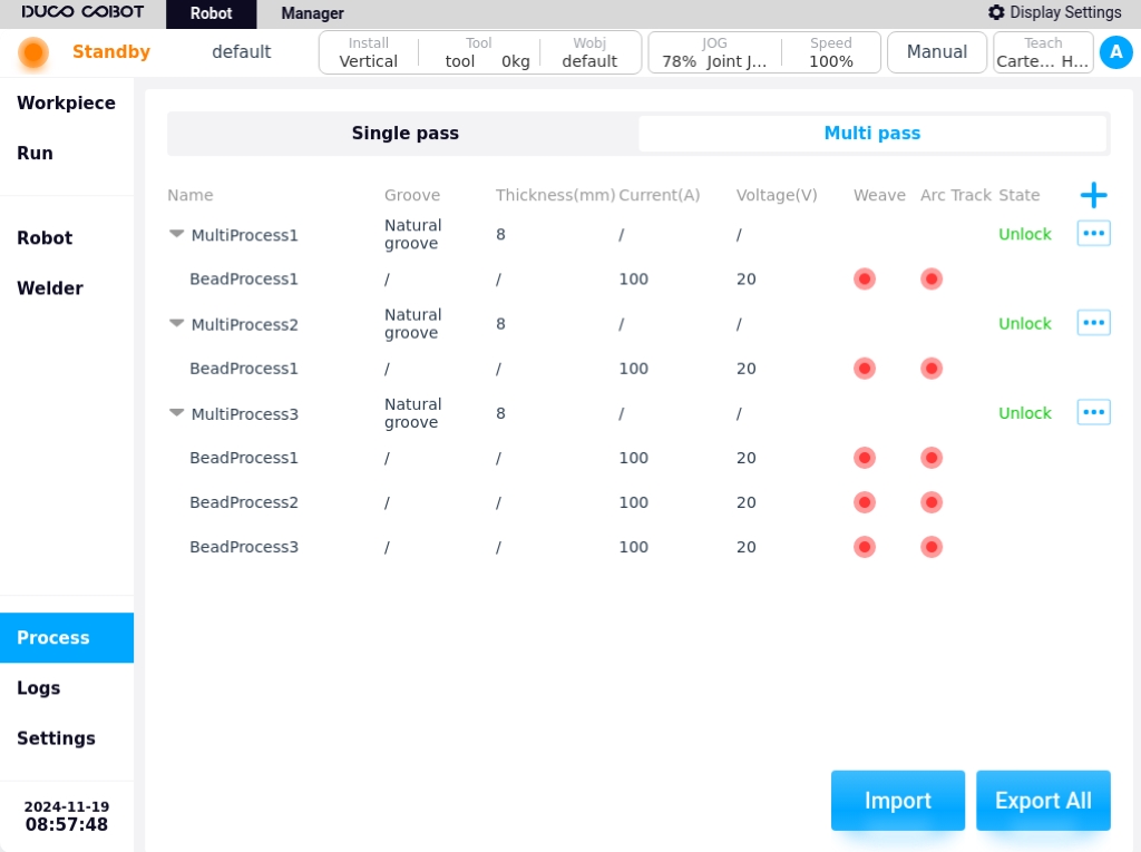
For example, the newly created “Multilayer Multi-Pass Process 3” has 3 passes added, as shown in the figure below.
icons to edit the process parameters of the corresponding weld passes.
After editing the process parameters, click “Save” button to return to the process list page. Users can also delete a process by clicking the “Delete” button on the process editing page.
For example, the newly created “Multilayer Multi-Pass Process 3” has 3 passes added, as shown in the figure below.
Similarly, clicking on any of the Multi-Layer Multi-Pass Process List icons results in the pop-up window shown below. The operation functions of multi-layer multi-channel processes are described in the Single Process Operation Functions, which will not be repeated here.
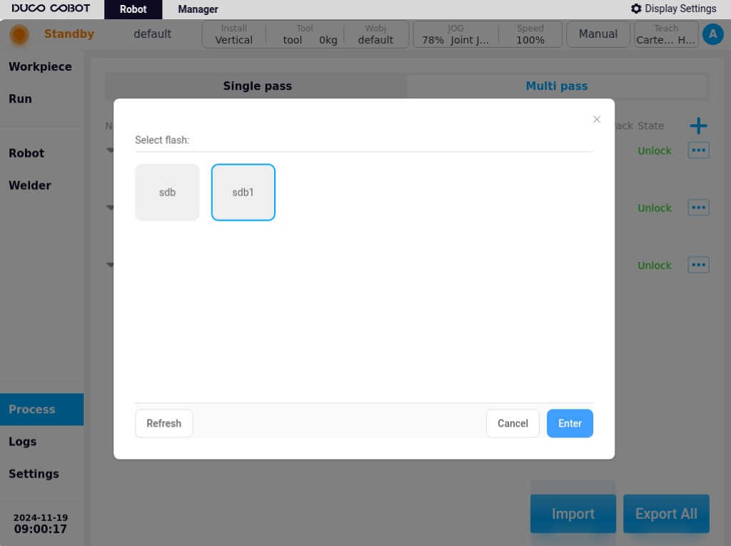
Click the “Import” button in the lower right corner of the process library page to bring up a window showing the USB storage devices currently mounted on the control cabinet, as shown in the following figure.
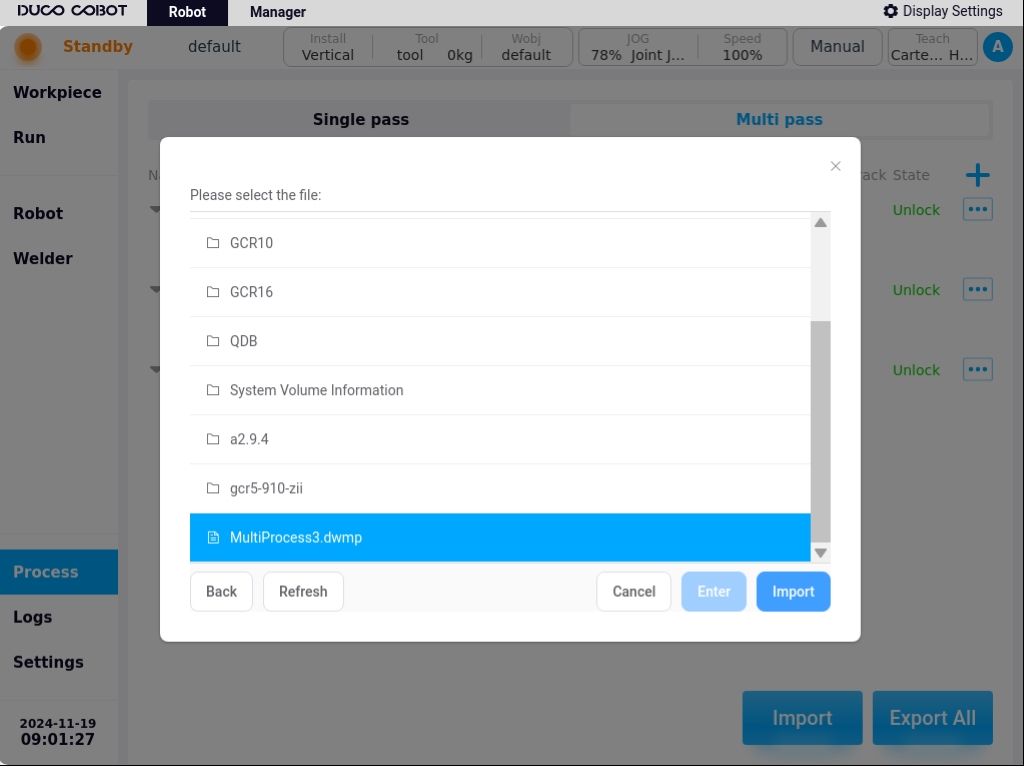
Select a device and the page displays the folders and eligible files in that device. Where the single-pass process file zip package has the suffix dwp, the The multi-layer multi-channel process file zip file has the suffix dwmp, as shown in the figure below. Selecting a file and clicking the “Import” button will import the file into the cabinet.
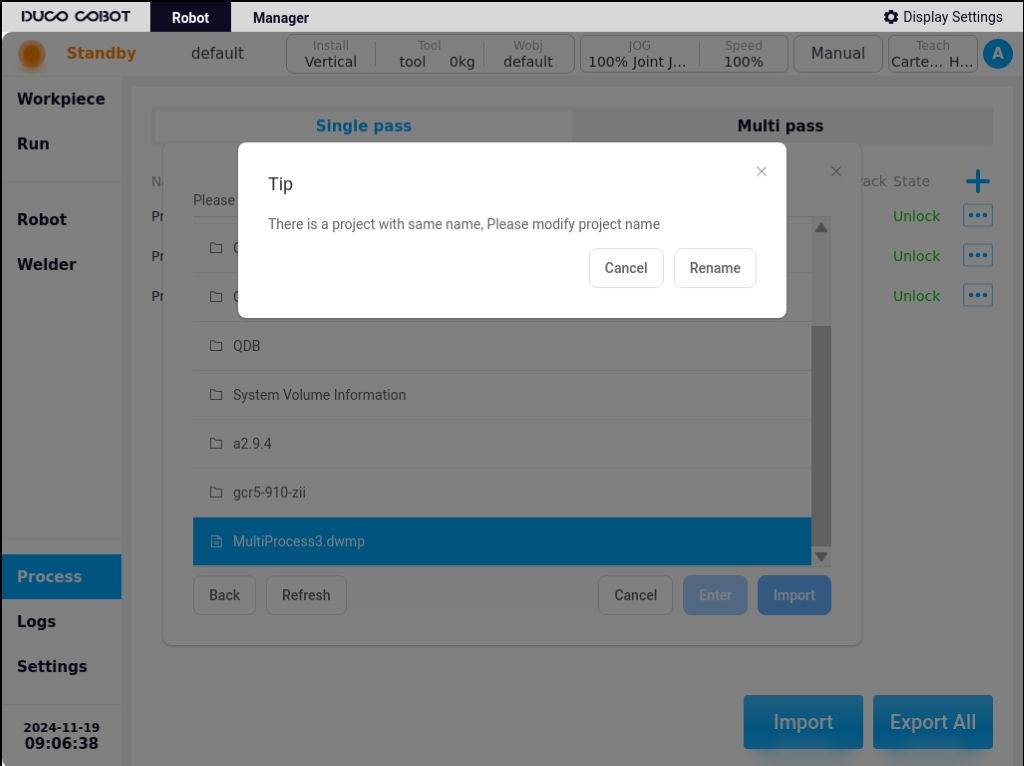
When importing a file and checking that the imported file is renamed with the workpiece on the control cabinet, a rename prompt box will pop up. For example, if you select the single-pass process zip file “Process 1.dwp”, the pop-up window is shown below.
Click the “Change Import Name” button, the keyboard will pop up, enter the new name of the artifact, such as “pro_test”, after the import is successful, it will be displayed as below in the list of single-pass processes sub-page.

Similarly, if the user selects a multi-layer multi-channel process zip archive will add a new multi-layer multi-channel process information display on the Multi-Layer Multi-Channel Process List sub-page after successful import.
Click the “Export All” button at the bottom right corner of the process page to bring up a window showing the USB storage devices mounted on the current control cabinet, select the export location and click the “Export” button. Then all the process files of single-channel process and multi-channel process will be compressed and packaged and exported to the USB device, and the exported compressed package will be named as “processLib.plib”.