


Joystick Control Traction Module#
Confirmation of Bill of Materials#
Serial No. |
Material Name |
q uantities |
1 |
Nylon Insulation Board |
1 |
2 |
T - Shaped flange |
1 |
3 |
Fastening accessory kit |
9* |
4 |
Torch holder assembly with countersunk nut |
1* |
5 |
Joystick Control Traction Module |
1 |
*Fastening accessory kit: 4 hex socket cap screws M4×20 + 4 insulating screw sleeves for M4 + 1 plastic insulating dowel pin φ6×20
*Torch holder assembly with countersunk nut:Welding torch included
Preparation before installation#
Remove the components installed on the end of the robot.
Correctly install the rocker traction module and weld plug-in package, and configure the welding working environment.
Jog the robot to position the end of the robot at a place convenient for installation.
Cut off the power supply of the robot.
Installation of torch holder and adapter flange#
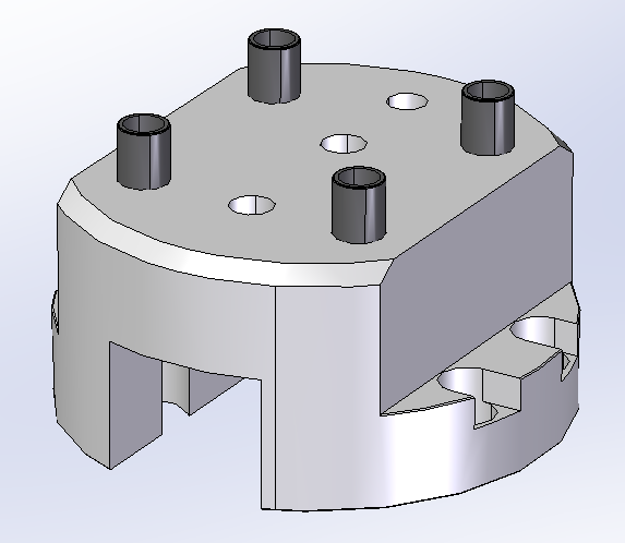
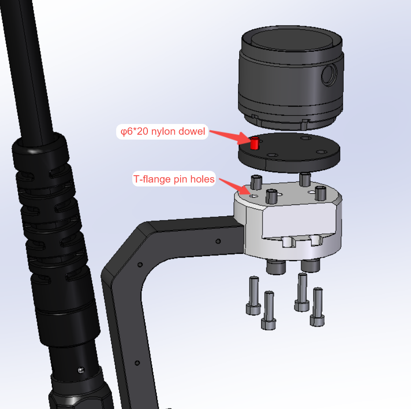
Put an M6 insulating pin sleeve in each of the 4 large holes of the T-shaped flange.
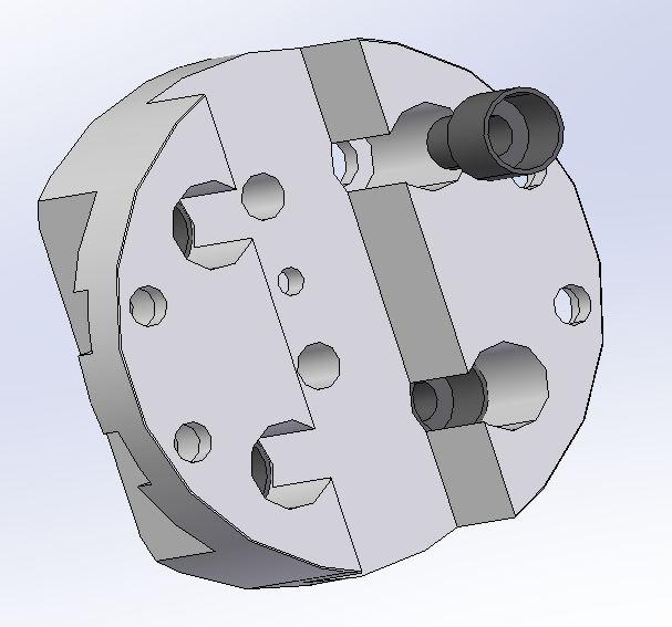
Install the welding torch bracket onto the corresponding mounting holes of the T - shaped flange using one φ4X10mm dowel pin and two M8 screws. Pay attention to tightening the two screws. The installation direction of the welding torch bracket should face the side opposite to the eccentricity of the mounting holes of the T - shaped flange.
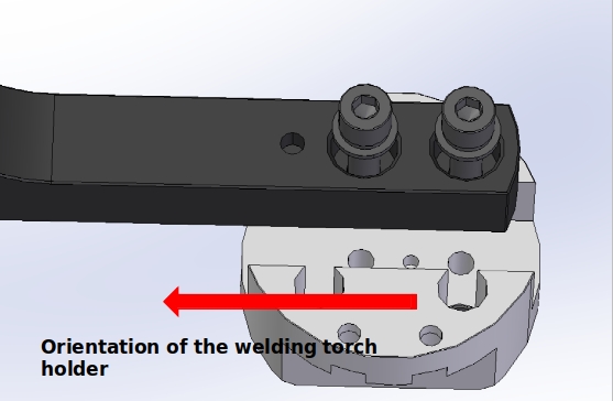
Determine the installation direction of the welding torch holder according to the φ6X20 nylon insulating dowel pin. Place the nylon Insulation board above the T-shaped flange. Use M6×20 screws to assemble and install the welding torch holder at the end of the robot through the M6 dowel pin insulating sleeve. The connection direction is as shown in the figure.
Install the Joystick Control Traction Module#
According to the φ6X20 nylon insulating pin, determine the installation direction of the Joystick Control Traction Module.Using four M4 bolts and matching insulating nylon sleeves, the nylon insulating plate and rocker traction module are installed at the lower end of the T-shaped flange through the countersunk hole on the T-shaped flange;Note that the nylon insulating plate is between the T-flange and the yo-ah dry traction module. The mounting orientation is shown in the figure below, so that the joystick is on the left hand side when looking along the torch holder towards the end of the robot.
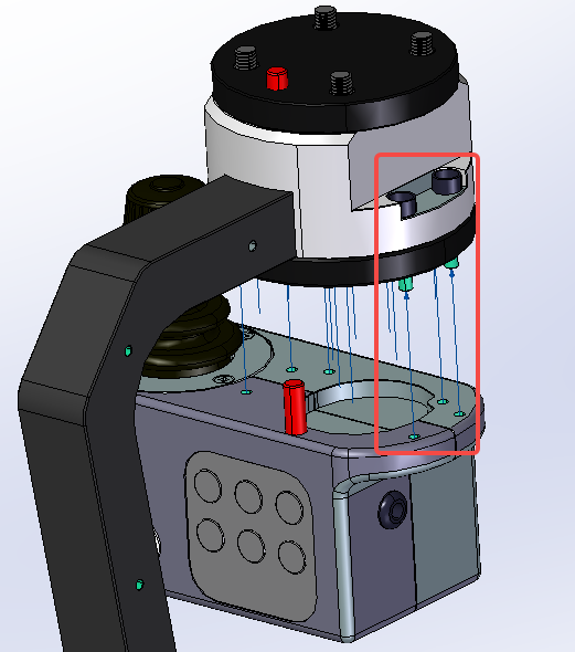
Confirm that the robot is in a power-off state, connect the aviation plug of the joystick traction module with the plug at the end of the robot, tighten the threaded sleeve on the plug and power on the robot.
Setup of the robot and joystick traction module#
Install the plug-in for the welding process package (V2.3.0 or later).
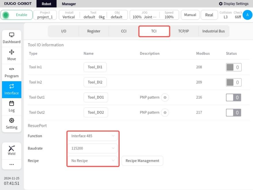
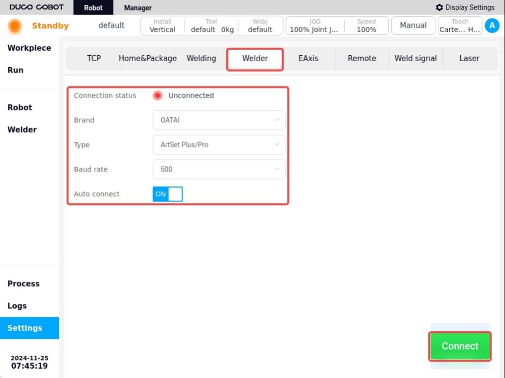
Setup in Robot Main Interface/Interface/TCI, refer to the figure below.
Click the corresponding icon in the lower left corner of the robot to enter the arc welding process package interface.
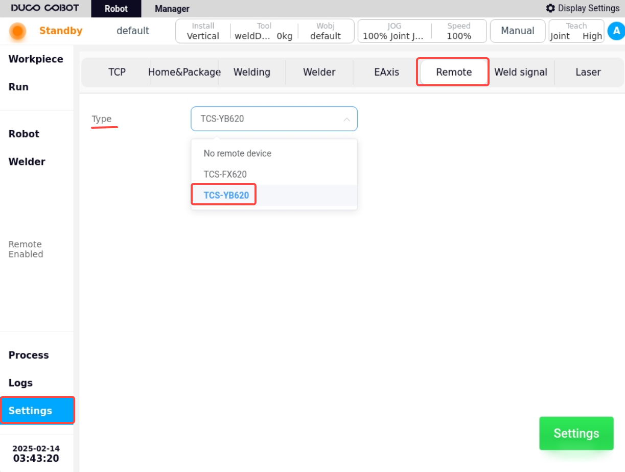
a. Under Basic Settings/Joystick Configuration, select the joystick type as TCS-YB620, and click Settings, and a prompt window of “Setup Successful” will pop up.
b. Under Basic Settings/Welder Settings, select the model of the welder to which the current robot is connected and make the connection. If the actual welder is not connected, you can choose the OATAI welder for setting, please refer to the following figure for details.
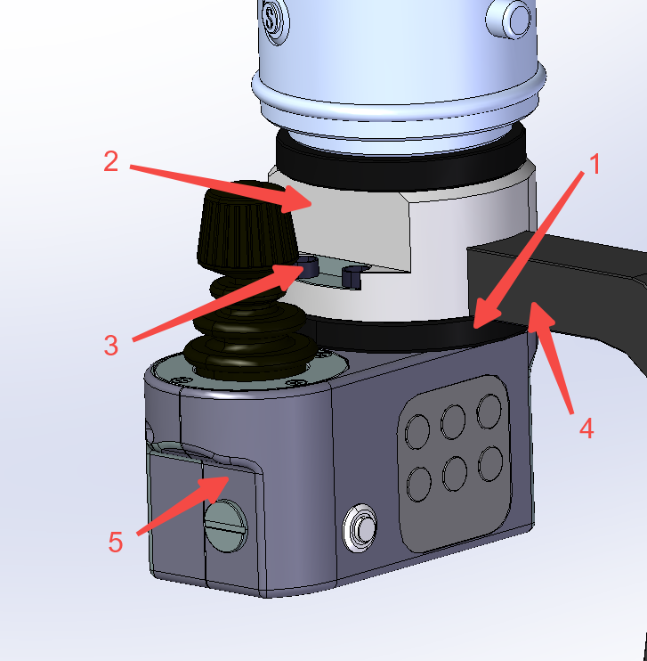
Introduction to the functions of the joystick traction module#
The joystick traction module is used to improve the accuracy and interaction friendliness of the customer during the traction teaching process with the robot. The key functions are described as follows:
Serial No. 1: Traction button, press and hold this button to start the joystick drag traction, release the button to stop traction.
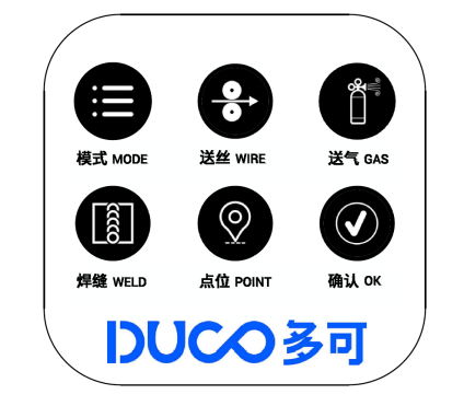
Serial No. 2: welding function button, from top to bottom, from left to right, the functions are: MODE, WIRE, GAS,WELD, POINT and OK six function buttons.
MODE: Toggle the traction mode ,to switch between joint traction and Cartesian traction.
WIRE: jog wire feeding, adjust the dry elongation of the welding wire.
GAS: Press and hold the air supply, release and close the air supply, which is used to detect the gas.
WELD: A button to create a weld that can be pressed repeatedly to switch between different types of welds.
POINT: Teach-in point record button, click to record points in order during weld definition. Press and hold to delete the teaching point of the current record.
OK: After the weld teach-in is complete, click this button to confirm the weld and prepare for execution.
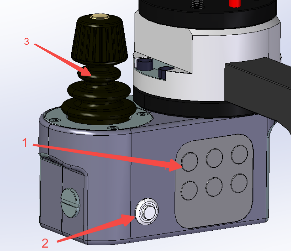
Serial No. 3:Operate the joystick, with a total of three self-resetting operable axes and 1 button; The operation axis controls the position and attitude change of the robot in space, and the button switches to control the movement mode of the robot. When the joystick is turned on and when the joystick is not used for 60s, the joystick mechanism will enter the safe locking state, and you need to press and hold the traction trigger button for 3s to unlock it.
When the machine is turned on, the attitude of the welding torch is locked by default, and the movement mode (lock attitude) of the spatial position of the welding torch at the end of the robot is adjusted:
Main operating axis (X, Y angle axis): Controls the lateral movement of the welding torch in the direction of the X and Y axes;
Z-operating axis (rotation axis): Controls the welding torch to move up and down in the Z-axis direction;
Click the button to switch the control mode to adjust the torch attitude (lock point) for locking the welding point:
Main operating axis (X, Y angle axis): control the rotation of the welding torch with the X and Y axes of the TCP coordinate system as the rotation axis;
Z-operating axis (rotation axis): control the welding torch to rotate with the Z axis of the TCP coordinate system as the rotation axis;
Click the button again to switch the movement mode to (Lock Pose).
Mode: Reserved function button, not yet enabled;
Wire Feed: Tap to feed the wire, adjust the wire dry elongation
Gas feed: press and hold to feed gas, release to turn off gas, used for detecting gas.
Weld Seam: button for creating weld seam, successive key presses allow switching between different types of weld seams.
Points: Button for recording the oscillometric points, when clicked, the points are recorded sequentially during the weld seam definition process. Press and hold down the button to delete the current recorded points.
Acknowledgement: After the weld is taught, click this button to confirm the weld and prepare for execution.