Force Control Traction Module#
Confirmation of Bill of Materials#
Serial No. |
Material Name |
q uantities |
|---|---|---|
1 |
Nylon Insulation Board |
1 |
2 |
Adapter Flange |
1 |
3 |
Fastening accessory kit |
9 |
4 |
Torch holder assembly with countersunk nut |
1 |
5 |
Force controlled traction module |
1 |
Fastening accessory kit: 4 hex socket cap screws M4×20 + 4 insulating screw sleeves for M4 + 1 plastic insulating dowel pin φ6×20
Preparation before installation#
Remove the components installed on the end of the robot.
Install the force - control and welding torch plug - ins correctly and configure the welding working environment properly.
Jog the robot to position the end of the robot at a place convenient for installation.
Cut off the power supply of the robot.
Installation of torch holder and adapter flange#
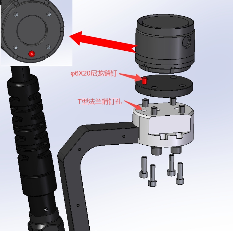
Place one M6 insulated dowel sleeve in each of the four large holes of the T-shaped flange.
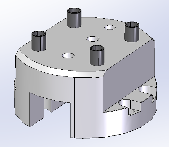
Install the welding torch bracket onto the corresponding mounting holes of the T - shaped flange using one φ4X10mm dowel pin and two M8 screw bushings. Pay attention to tightening the two screws. The installation direction of the welding torch bracket should face the side opposite to the eccentricity of the mounting holes of the T - shaped flange.
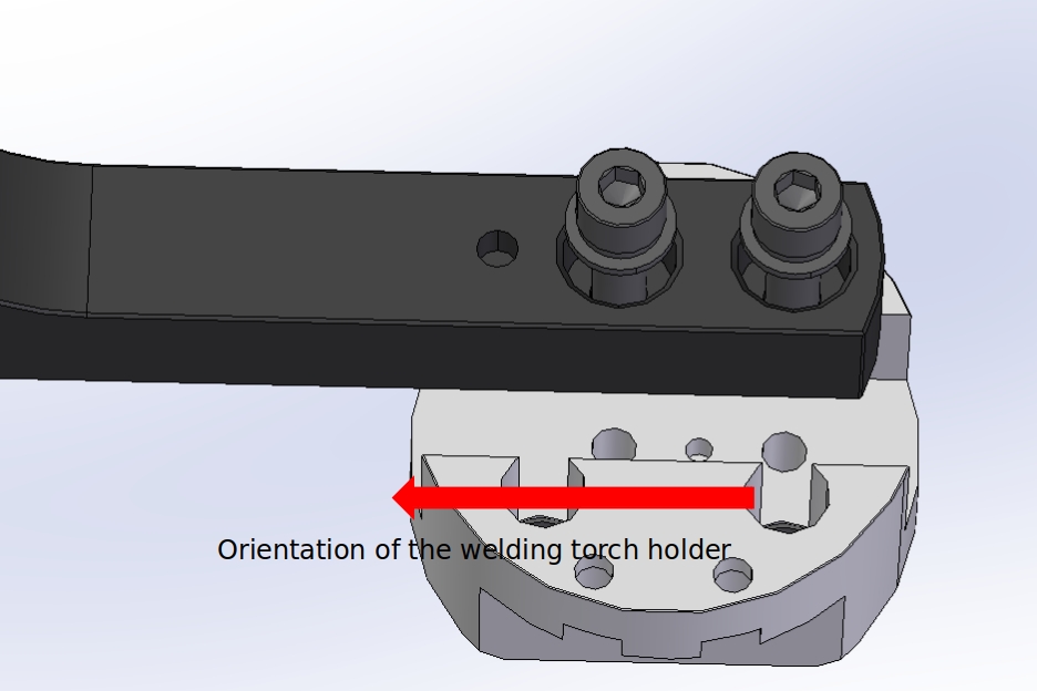
Determine the installation direction of the welding torch holder according to the φ6X20 nylon insulating dowel pin. Place the end insulating plate above the T-shaped flange. Use M6×20 screws to assemble and install the welding torch holder at the end of the robot through the M6 dowel pin insulating sleeve. The connection direction is as shown in the figure.
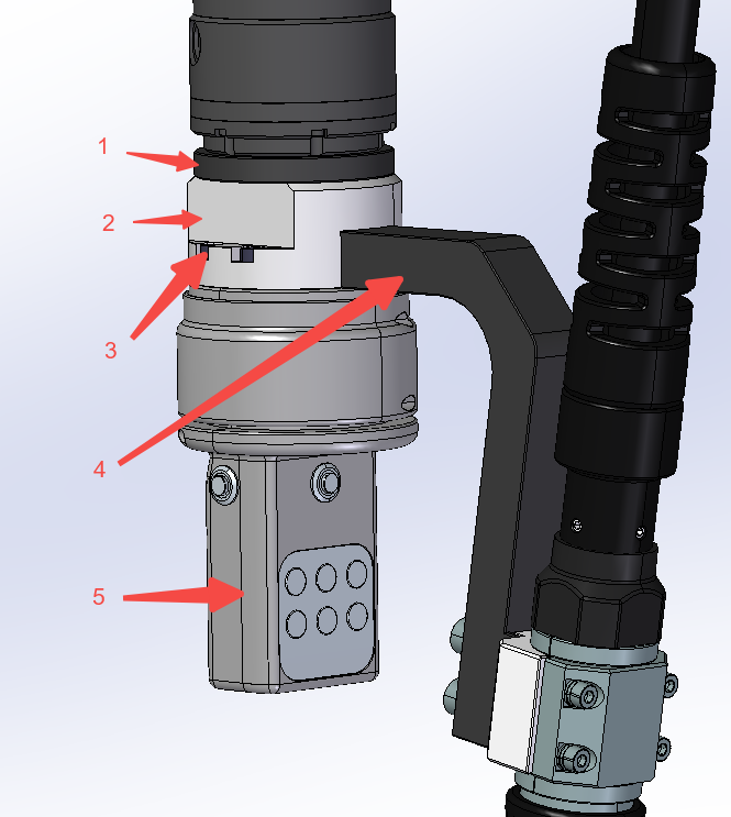
Installation of force control module#
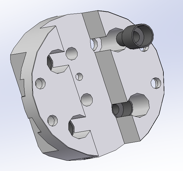
Using four M4 bolts and matching nylon bushings, install the force control module on the lower end of the adapter flange through the countersunk holes on the adapter flange. The mounting direction is shown in the figure below. Be careful to adjust the mounting position so that the side of the button faces the same direction as the deep projection of the torch bracket.
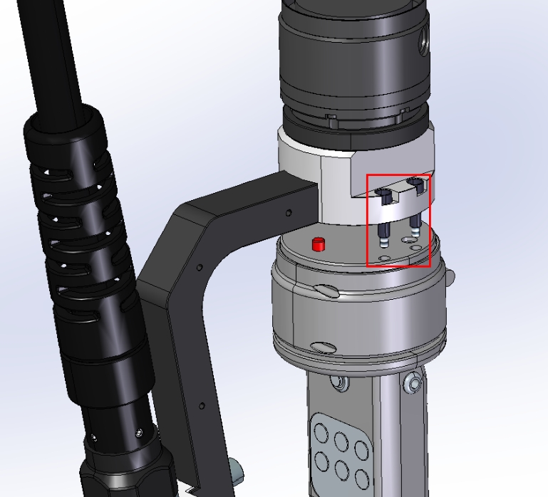
Connect the two air plugs (6pin and 8pin) of the force control traction module to the air plugs on the end of the robot.
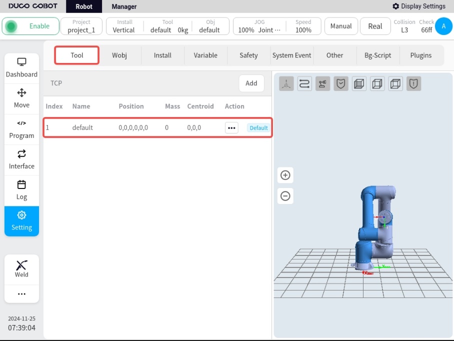
Robot and force control traction module setup#
Install the Force Control Plug-in (V1.3.1 or above) and Welding Process Package Plug-in (V2.1.2 or above).
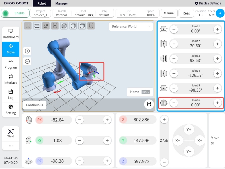
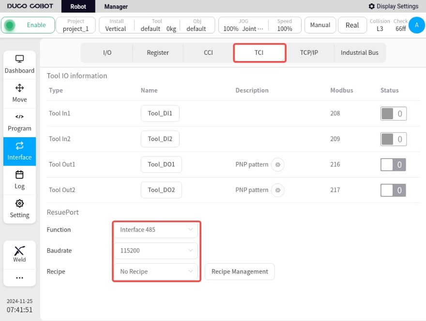
Setup in Robot Main Interface/Interface/TCI, refer to the figure below.
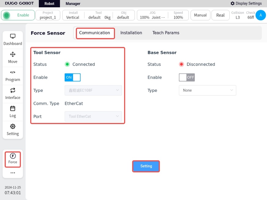
In the main interface of the robot, click on the force sensor plug-in in the lower left corner to enter the force sensor configuration interface:.
Enable: ON
Model selection: Xin Jing Cheng EC108F
Communication mode: EtherCat
Input port: End EtherCat port
After the setup is completed, press Setup, confirm the status, etc. shows a green light, indicating a successful connection.
Click on the bottom left corner of the robot to enter the Arc Welding Process Package screen.
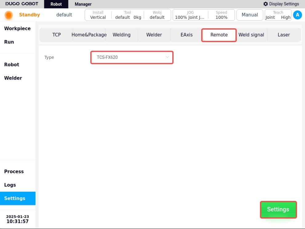
a. Under Basic Settings/Rocker Configuration, select the rocker type TCS-FX620, click Set, and the “Setting Successful” pop-up window will appear.
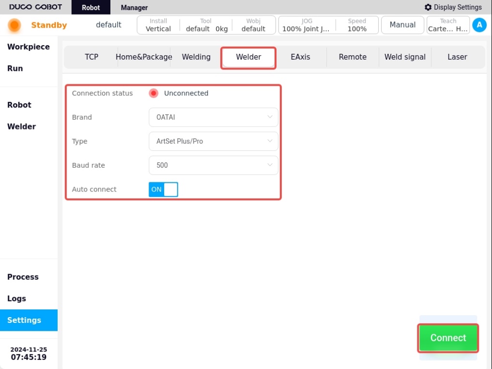
b. Under Basic Settings/Welder Settings, select the type of welder that the robot is currently connected to, and make the connection. If there is no actual welder connected, you can select AOTAI welder to set up, refer to the following figure for details.
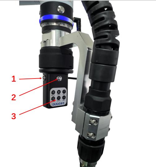
Introduction to the functions of the Force Control Traction Module#
The force-controlled traction module is used to improve the suppleness and interaction friendliness of the customer during the traction teaching process with the robot. The key functions are described below:
Serial No. 1: High and low speed switching, press this button (1S) during towing to switch back and forth between high and low speeds.
Serial No. 2: Force-controlled towing trigger button, long press this button to start force-controlled towing, release the button to stop towing.
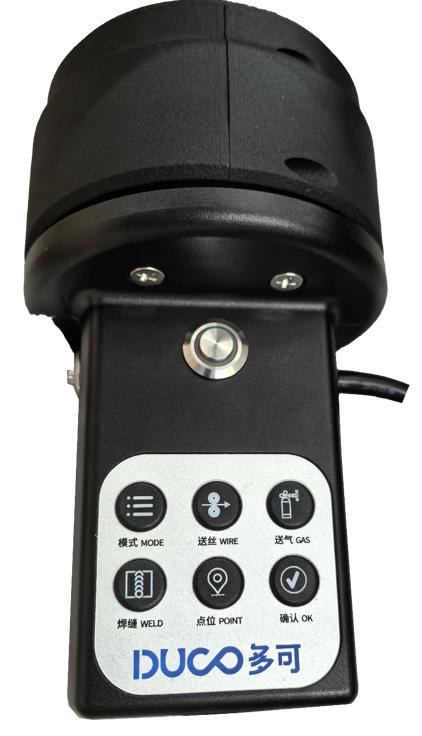
Serial No. 3: Welding Function Buttons, from top to bottom, from left to right, the functions are in order: mode, wire feed, gas feed, weld, spot and confirm six function buttons.
Mode: Reserved function button, not yet enabled;
Wire Feed: Tap to feed the wire, adjust the wire dry elongation
Gas feed: press and hold to feed gas, release to turn off gas, used for detecting gas.
Weld Seam: button for creating weld seam, successive key presses allow switching between different types of weld seams.
Points: Button for recording the oscillometric points, when clicked, the points are recorded sequentially during the weld seam definition process. Press and hold down the button to delete the current recorded points.
Acknowledgement: After the weld is taught, click this button to confirm the weld and prepare for execution.