Force Sensor Integration#
Sensor mounting#
Before using the robot end force control, the user needs to install the force sensor on the robot system. Users can choose to use the end force control function by integrating an end force sensor or an integrated base force sensor.
If you choose to use the end force sensor, it is necessary to install the end force sensor on the end flange of the robot, and correctly connect the communication interface and power supply interface between the relay sensor and the end flange of the robot, and ensure that the communication line and the power supply line will not wind, knot, excessive bending and other phenomena affecting the normal work of the robot and the end sensor.
If you choose to use the base force sensor, it is necessary to correctly install the robot on the base sensor of the robot, and correctly connect the relay sensor to the robot control cabinet communication interface and power supply interface, and ensure that the communication safety and power supply line will not wind, knot, excessive bending and other phenomena affecting the normal work of the sensor.
When both the base force sensor and the end force sensor are integrated in the controller system, the system preferentially uses the end force sensor data to perform the end force control function.
Sensor integrated topology import#
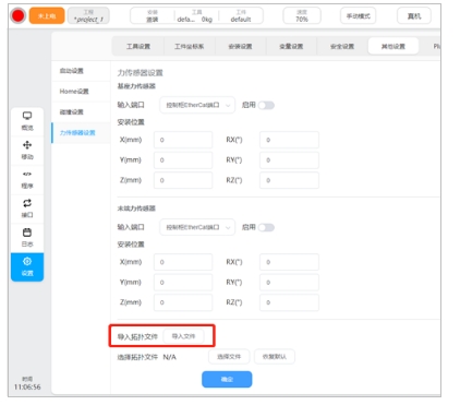
Before using the robot end force control, the user needs to enter the corresponding sensor integration topology to take effect the integrated system configuration, as shown in the figure below:
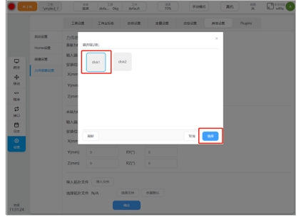
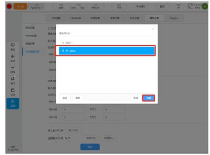
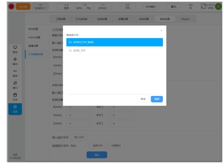
After obtaining the corresponding sensor integration topology, the user saves the topo file to the USB flash drive and inserts it into the control cabinet. Click to select the file, select the corresponding target path and file in the pop-up dialog box, and click “Select” button to import the corresponding topology file, as shown in the following figure:
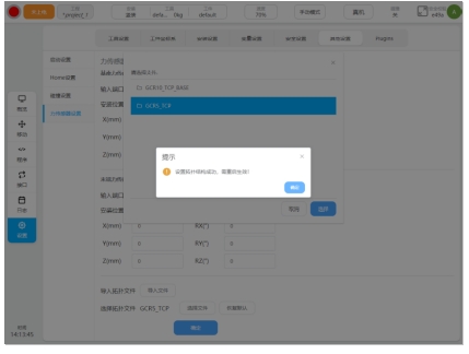
After the sensor integration topology is imported, you can find the corresponding topology option in the sensor integration system topology file list to enable the corresponding integration topology.
Sensor integration topology selection#
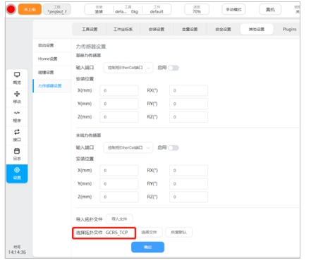
After importing the sensor integration topology correctly, select the corresponding sensor integration topology and enable it to take effect, as shown in the following figure:
Click the button to select topology file, and the user can see the list of sensor integrated topologies that have been imported and stored, as shown in the following figure:
After connecting the sensor to the system, you need to select the corresponding option in the sensor integration topology list, and the system topology after the integrated sensor is enabled and takes effect, as shown in the following figure:
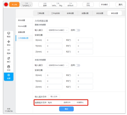
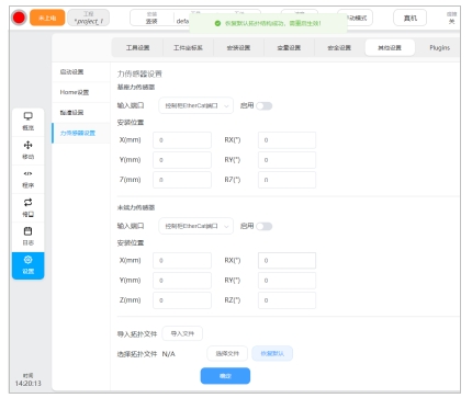
After replacing the sensor model and changing the sensor access interface, you need to import and select the sensor integration topology option again to enable and take effect the sensor integration robot system after the change. After the sensor is removed, you can use Restore Default to restore the sensor integrated topology to the initial topology configuration of the robot arm. After the restoration is successful, the dialog box “Restore the default topology successfully, need to restart to take effect” is displayed at the top of the page, and the options for the current active topology file are displayed N/A, as shown in the following figure:
Sensor installation position configuration#
After installing the force sensor, the user needs to correctly configure the installation position of the sensor, as shown in the following figure:
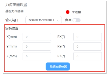
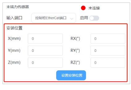
If the end force sensor is selected, where X/Y/Z is the position offset of the origin of the force surface coordinate system of the end force sensor in the robot’s end flange coordinate system (unit mm); RX/RY/RZ refers to the RPY rotation deviation of the attitude of the force surface coordinate system of the end force sensor in the coordinate system of the end flange of the robot. The rotation order refers to the Z-Y-X rotation axis order, in unit of degree. If the base force sensor is selected, where X/Y/Z is the position offset of the origin of the robot base coordinate system in the base force coordinate system of the base sensor, in mm; RX/RY/RZ refers to the attitude PRY rotation offset of the robot base coordinate system in the load coordinate system of the base sensor. The rotation order refers to the Z-Y-X rotation axis order, in unit of degree. After correctly filling in the installation position of the force sensor, click Set Installation Position to take effect.
Enable sensor#
On the basis of correctly configuring the installation position and port configuration of the robot manpower sensor and correctly connecting the sensor hardware, you can click the enable button to activate the sensor, as shown in the following figure:
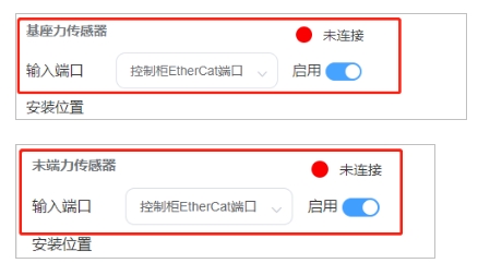
If the sensor hardware is properly connected and working when the force sensor is enabled, the sensor activation indicator will be green and indicate that it is connected, otherwise the activation status indicator will be red and indicate that it is not connected. After the sensor is normally enabled, the user can normally use the relevant functions and programming programs of the end force control. If the user disconnects the sensor or the sensor works abnormally during use, the robot will generate corresponding errors. If the user needs to continue using the end force control function, the sensor needs to be re-connected.