End Force Programming#
Function description#
The user chooses to use the end force control programming function, which can realize the robot to add the force control function in the program operation process, so that the robot can adjust according to the information of the interaction force with the outside world during the movement of the robot, so that the user can control the robot to maintain a specific interaction force with the outside world in the specified Cartesian space direction.
Function restriction#
When using the end force programming function, users need to pay attention to the following functional limitations:
Properly configured and enabled force sensors are required to use this feature.
Only the interaction force between the end of robot and the sensors, tools and loads installed on the end and the outside world will be perceived, and the contact between other parts of the robot and the outside world will not produce any effect.
This feature is not supported in threaded programming.
end force control program#
When the user chooses to use the end force programming function, the end force control program can be added in the robot program programming interface - Advanced program, as shown in the following figure:
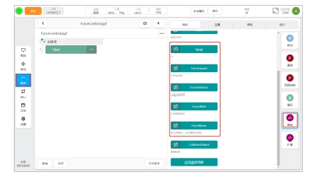
End force control procedures include:
Force
ForceGuard
ForceSetZero
ForceWait
ForceMove
Force program#
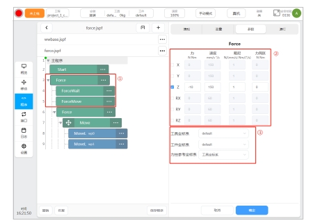
The user can choose to use the Force program to control the robot to interact with the outside world in the direction specified in the Cartesian space extended coordinate system during movement, as shown in the following figure:
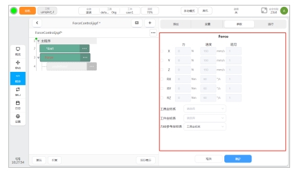
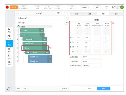
If you use the Force program, you need to set force control parameters. The Force program parameter configuration interface is shown in the following figure:
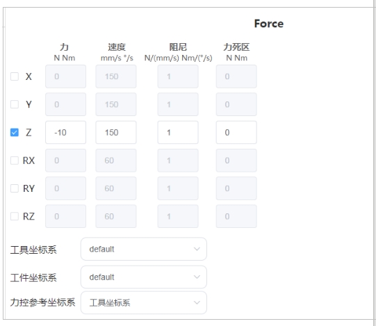
Force control direction switch
The user can enable/disable the force control corresponding to the specified direction in the Cartesian space coordinate system by checking the force control direction switch.
The above direction of Force control is based on the direction corresponding to the reference coordinate system of force control. When the user selects the reference coordinate system of force control as the tool coordinate system, the force control direction will be carried out along the tool coordinate system configured in the force program. When the user selects the reference coordinate system of force control as the workpiece coordinate system, The direction of Force control is controlled along the workpiece coordinate system configured in the Force program.
Force control direction reference force
The user enables the force control backward, and controls the end of robot to generate and maintain the target force with the outside world in the specified direction by configuring the reference force parameters, in units of N and Nm. When the user has configured a non-zero target force and the end of robot does not reach the target interaction force with the outside world, the robot end will continue to move along the corresponding force control direction until the interaction force reaches the reference force configured by the user.
The reference force is the description of the force acting on the end of robot in the force control reference coordinate system configured by the user, so the user needs to adjust the size and symbol of the target force parameters according to the actual situation. When the target force direction is positive in the translation/rotation direction along the coordinate system in the force control reference coordinate system, the reference force value is positive. When the target force direction is negative in the force control reference coordinate system along the translation/rotation direction, the reference force value is negative.
Maximum speed of force control direction
The end of robot will shift based on the reference force and damping parameters set by the user. The user can set the maximum speed in the force control direction to limit the maximum speed of the upward displacement due to the force control, in mm/s and °/s.
Directional damping of force control
The user can adjust the relationship between the error of the actual interaction force and the reference interaction force between the end of robot and the outside world and the adjustment speed of the stress control direction by configuring the direction damping of the force control.
The damping d unit N/(mm/s) in the X/Y/Z direction of the force control translation direction. The actual interaction force and reference force error ΔF(N) between the end of robot and the environment in the force control translation direction will generate the force control translation adjustment speed ΔF/d(mm/s) for the stress control translation direction.
Force control rotation direction RX/RY/RZ direction damping d unit Nm/(°/s). The actual interaction torque and reference torque error ΔM(Nm) between the end of robot and the environment in force control rotation direction will generate a force control rotation adjustment speed ΔM/d(°/s) for the stress control rotation direction.
Force control direction force dead zone
When the user enables the force control backward, the detection dead zone of the actual interaction force between the end of robot and the outside world can be adjusted by configuring the force control direction dead zone. When the value of the actual interaction force between the end of robot and the outside world is less than the dead zone range, the end of robot will not produce the corresponding force control adjustment motion for the interaction force.
Dead zone unit N in the X/Y/Z direction of the force control translation direction, and Nm in the RX/RY/RZ direction of the force control rotation direction.
Force control tool coordinate system
The user sets the force control tool coordinate system, and the robot end force control will take the origin of the force control tool coordinate system as the action point of the actual interaction force between the robot end and the outside world, and the force control adjustment translation/rotation due to the force control direction will take the origin of the force control tool coordinate system as the reference point.
When the user selects the force control reference coordinate system as the tool coordinate system, the force control direction configured and enabled by the user will be translated/rotated along the direction of the tool coordinate system when the force control is enabled, and the corresponding force control reference force is described in the tool coordinate system when the force control is enabled.
Force control workpiece coordinate system
When the user sets the force control tool coordinate system and selects the force control reference coordinate system as the workpiece coordinate system, the force control direction configured by the user will be translated/rotated along the direction of the workpiece coordinate system, and the corresponding force control reference force is described in the workpiece coordinate system.
Force control reference coordinate system
When the user chooses to use the end force control function, the final force control effective coordinate system needs to be determined. The user can select the end force control for force adjustment along the tool coordinate system or the workpiece coordinate system.
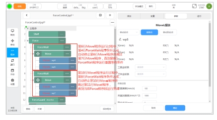
Motion program end force control integration
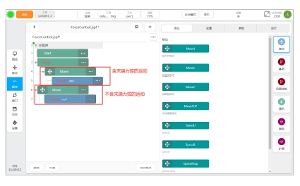
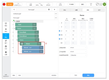
After the Force program is correctly configured, the user can add the Move program under the Force program. All the Move programs under the Force program node will perform end Force control based on the force program configuration parameters during movement. The Move program that is not added under the Force program node does not have the end force control adjustment function, as shown in the following figure:
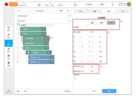
ForceGuard program#
The user choosing to use the ForceGuard program can be used to activate/disable the interaction force based on the size of the end, as shown below:
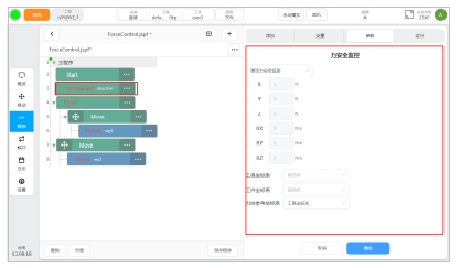
To use ForceGuard, users need to configure the activation/shutdown state, monitor the force direction, monitor the force magnitude, monitor the tool coordinate system, monitor the workpiece coordinate system, and monitor the coordinate system.
Active/Off state
After the ForceGuard program is run and the user selects active safety monitoring, when the robot is running a program with end force control, if the interaction force acting on the end of robot exceeds the monitoring force in the direction specified in the monitoring coordinate system, the safety stop Class 1 is triggered.
After the ForceGuard program runs and the user chooses to turn off force security monitoring, the monitoring fails.
Safety force monitoring is activated only when the robot is running a program that includes end force control.
When a user activates safety monitoring using ForceGuard and does not disable force safety monitoring through ForceGuard, the Force safety monitoring feature is continuously monitored with an effective parameter until the user disables or modifies the force safety monitoring configuration using ForceGuard.
Monitoring force direction
By checking the monitoring force direction switch, the user can enable/disable the force monitoring for the specified direction in the corresponding Cartesian space monitoring coordinate system.
The above monitoring force directions are based on the corresponding direction of the monitoring reference coordinate system. When the user selects the monitoring reference coordinate system as the tool coordinate system, the monitoring direction will be monitored by referring to the tool coordinate system configured in the ForceGuard program. When the user selects the monitoring reference coordinate system as the workpiece coordinate system, the monitoring force direction will be monitored by referring to the tool coordinate system configured in the Forceguard program. The monitoring direction is monitored along the workpiece coordinate system configured in the ForceGuard program.
Monitoring power size
After the user opens the monitoring force direction, the monitoring force size can be configured to adjust the force size assignment that triggers the monitoring alarm to stop, in units of N and Nm.
The user should ensure that the monitoring force in the direction of the active safety monitoring is a non-zero positive number, so as to ensure the normal operation of the force safety monitoring.
Monitor tool coordinate system
Users configure the monitoring tool coordinate system, and the end of robot safety force monitoring will take the origin of the monitoring tool coordinate system as the action point of the actual interaction force between the end of robot and the outside world.
When the user selects the monitoring reference coordinate system as the tool coordinate system, the monitoring direction configured by the user will monitor the force/moment along the direction of the real-time tool coordinate system, and the corresponding monitoring force direction is described in the robot real-time tool coordinate system.
Monitor the workpiece coordinate system
When the user configures the monitoring tool coordinate system and selects the workpiece coordinate system as the monitoring reference coordinate system, the force/moment monitoring direction configured by the user is carried out along the direction of the workpiece coordinate system, and the corresponding monitoring force direction is described in the workpiece coordinate system.
Monitor reference coordinate system
When the user chooses to use the end force safety monitoring function, the final monitoring system needs to be determined. The user can select the end force safety monitoring control to monitor along the tool coordinate system or the workpiece coordinate system.
ForceSetZero program#
The user can choose to use the ForceSetZero program to clear the current sensor reading, as shown below:
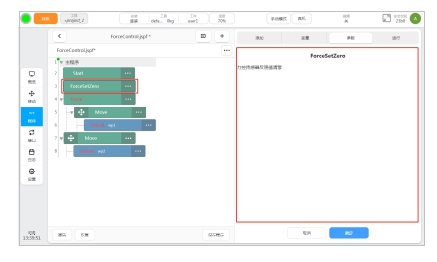
After the user uses and the program executes the ForceSetZero program, all current loads acting on the forces of the end of robot, including the weight of the tool load installed on the end of robot and all external forces acting on the end tool load, are emptied. Then modifying the tool load installed at the end of robot or interacting with the outside world will produce the corresponding error force.
ForceWait program#
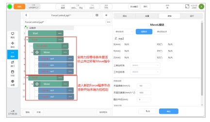
If the user chooses ForceWait program, the motion program can automatically jump out of the current Force program segment after the end of robot-force control waiting condition is met, until the new ForceWait program is executed in the current Force program segment or the current Force program runs out, as shown in the following figure:
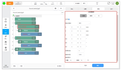
When the user chooses to use the ForceWait program, the relevant force control waiting conditions need to be configured. The current user can configure the force control waiting condition parameters, including position waiting condition, speed waiting condition, force waiting condition and force control waiting condition activation logic.
Position waiting condition
When the user chooses to enable the position wait condition, the position wait condition parameter can be set by configuring the absolute position on X/Y/Z/RX/RY/RZ and the offset range relative to the absolute position.
If the absolute position parameter and offset position parameter are both 0, the position waiting condition is not monitored in this direction.
When the user selects the absolute position waiting condition, the position monitored by the position waiting condition is the absolute pose of the origin of the Force control tool coordinate system configured in the force program where the ForceWait program is located in the force control workpiece coordinate system. When the user selects the relative position wait condition, the monitored position is the relative pose offset of the origin of the Force control tool coordinate system configured in the force program where the ForceWait program resides after running the ForceWait program.
By configuring the position waiting condition duration parameter, the user can adjust the duration of the end of robot position meeting and remaining within the waiting condition range, in ms. When the end of robot position is out of range, the duration is re-timed. When the duration is set to 0, the location wait condition is met and the location wait condition is met flag bit is activated immediately.
By configuring the timeout parameter of the position waiting condition, the user can adjust the waiting timeout time of the end of the robot when the position waiting condition cannot be met. The unit is ms. When the FoeceWait program is executed and exceeds the position waiting timeout time, the position waiting condition is met flag bit will be activated directly.
Speed waiting condition
When the user chooses to enable the position wait condition, the speed wait condition parameter can be set by configuring the absolute speed on X/Y/Z/RX/RY/RZ and the offset range relative to the absolute speed. When the absolute velocity parameter and the offset velocity parameter are 0 at the same time, it means that the speed waiting condition is not monitored in this direction.
When the user selects the absolute speed waiting condition, the speed monitored by the speed waiting condition is the absolute speed of the origin of the Force control tool coordinate system configured in the force program where the ForceWait program resides in the force control workpiece coordinate system. When the user selects the relative speed wait condition, the speed monitored by the lock is the speed increment after the ForceWait program is run by the origin of the Force control tool coordinate system configured in the force program where the ForceWait program resides. Since the robot is always in a static state when the end force control motion function begins, the absolute speed waiting condition is equivalent to the relative speed waiting condition for the speed waiting condition.
By configuring the duration parameter of the speed waiting condition, the user can adjust the duration of the end of robot speed meeting and remaining within the range of the waiting condition, in ms. When the end of robot speed is out of range, the duration is re-timed. When the duration is set to 0, the speed wait condition meets the speed wait condition meets the flag bit.
By configuring the speed waiting condition timeout parameter, the user can adjust the waiting timeout period (unit: ms) of the end of robot when the speed waiting condition cannot be met. When the FoeceWait program is executed and exceeds the speed wait timeout period, the speed wait condition is activated directly.
Force waiting condition
When the user chooses to enable the force wait condition, the force wait condition parameters can be set by configuring the absolute force size on X/Y/Z/RX/RY/RZ and the offset range relative to the absolute force. When the absolute force size parameter and the offset force range parameter are both 0, it means that the force waiting condition is not monitored in this direction.
The reference coordinate system of the Force waiting condition is the same as that of the Force control reference coordinate system configured in the force program where ForceWait program is located. That is, when the force control reference coordinate system is configured in the force program as the tool coordinate system, the force magnitude and direction monitored by the force waiting condition are described in the force control tool coordinate system. When the Force control reference coordinate system is configured as the workpiece coordinate system in the force program, the force magnitude and direction monitored by the force waiting condition are described in the force control workpiece coordinate system.
When setting the parameters of the Force waiting condition, the actual coordinate system configuration in the Force program where the ForceWait program is located should be referred to the setting, and attention should be paid to whether the symbol and size can be satisfied by the end force control function caused by the force program.
When the user selects the absolute force waiting condition, the force waiting condition monitors the absolute value assigned to the corresponding monitoring force. When the user selects the relative force wait condition, the force wait condition monitors the increment of the monitoring force after running the ForceWait program.
By configuring the force waiting condition duration parameter, the user can adjust the duration of the end of robot force meeting and remaining within the waiting condition range, in ms. When the end of robot force is out of range, the duration is re-timed. When the duration is set to 0, the dynamic waiting condition is activated at the moment when the force waiting condition is satisfied.
By configuring the force waiting condition timeout parameter, the user can adjust the waiting timeout time of the end of robot when the force waiting condition cannot be met, in ms. When the FoeceWait program is executed and exceeds the force wait timeout, the active wait condition is directly activated to meet the flag bit.
Force control wait condition activation logic
When multiple force control waiting conditions are enabled, you can configure the logical relationship between multiple force control waiting conditions by setting the force control waiting condition activation logic.
When there is AND logic in the force control wait condition activation logic, all enabled force control wait conditions need to be activated before the global force control wait condition is activated.
When there is or logic in the force control wait condition activation logic, the global force control wait condition is activated when any enabled force control wait condition is activated.
When both and logic and or logic exist in the force-controlled wait condition activation logic, any or logical force-controlled wait condition activation or all of the logical force-controlled wait condition activation will be considered as the global force-controlled wait condition activation.
Global force control condition activation
When the global Force control condition is met and activated, all Move programs under the corresponding force program will be stopped and adjusted, as shown in the following figure:
ForceMove program#
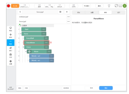
The user chooses to use the ForceMove program, which can make the end of robot produce only the end force control adjustment, without any MOve-like movement, as shown in the following figure:
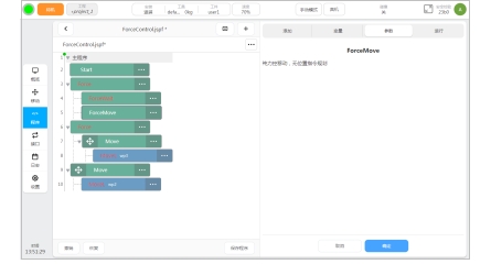
The ForceMove program can only be added to the Force program to achieve pure end force control movement.
When the user chooses to use the ForceMove program, the end force control will continue to adjust the end of robot position/posture based on force/moment until the conditions of the ForceWait program are met or the user manually stops/pauses. Therefore, when the user chooses to use the ForceMove program, the ForceWait program should be added before the ForceMove program and the condition parameters should be correctly configured, so as to ensure that the ForceMove program can meet the force control waiting condition during operation and exit the ForceMove program to run the following programs normally.
Examples of end force control programming#
End force control polishing
When the end of robot is designed to polish a certain surface, it is required that the end of robot has generated 10N grinding force with the surface at the beginning of grinding and continues to maintain 1s. After the grinding force meets the requirements, the end of robot is polished along the curved surface. The grinding path adopts two branch paths from point A to point B to point C. During the grinding process, the tool of the end of robot should always be kept perpendicular to the tangent direction of the surface.
Corresponding to the above working conditions, the design of the end force control programming program is as follows:
1、 The end of robot needs to explore in the direction of the grinding surface until the contact Force of 10N is maintained, and force control is carried out by force program and used with ForceMove program;
2、 The direction of the contact force in the robot tool coordinate system is negative, the target force is set as -10N, the maximum speed of force control adjustment is set as the default value of 150mm/s, the robot is expected to move towards the surface at a speed of 10mm/s, and the damping parameter is set as 1. In actual working conditions, if the end of robot cannot reach balance with the outside world, the damping parameter should be increased;
3、 Select the force control tool coordinate system and the workpiece coordinate system as the default coordinate system, and select the force control reference coordinate system as the tool coordinate system, corresponding to the set target;
4、 ForceMove program was used for force control exploration, and ForceWait program was used to monitor the activation of force waiting conditions;
5、 only the force direction has waiting conditions, only enable the force waiting conditions;
6、 It is necessary to monitor whether the force in the Z direction reaches and maintains -10N, select the relatively cheap range as plus or minus 2N, and select the offset range considering the contact stiffness between the tool and the polished surface in actual working conditions;
7、 need to hold force for 1s, that is, 1000ms, set the default timeout time 5000ms;
8、 Execute the ForceMove program and adjust the end of robot force control to move the end of robot towards the surface without any other direction motion planning. When the robot touches the surface, 10N force is generated and remains for more than 1s, jump out of the current ForceMove program and execute subsequent programs;
9、 open the end force control function again, so that the subsequent robot Move movement has the end force control adjustment;
10、 During the grinding process, the robot continues to generate 10N contact force with the grinding surface, and the direction is Z- in the tool coordinate system. At the same time, in order to ensure that the end of robot is always perpendicular to the tangential direction of the surface, the force control adjustment of the rotation direction of RX and RY is enabled, the reference torque is set to 0Nm, and the maximum adjustment speed of the optional direction is set to 60°/s. The damping parameters need to be adjusted according to the curvature of the surface in actual working conditions and the contact stiffness between the grinding tool and the surface.
11、 The two-line Move program under the Force program controls the robot to move from point A to point B to point C in A straight line path. Since the tool coordinate system Z is adjusted upward through force control, it is recommended that the teaching point of point A, point B, point C is the point directly above the surface in the XY plane, so that the adjustment direction of right-hand control is decouple from the direction of motion control. As far as possible to ensure the accuracy of both;
Based on the above programming example, the actual motion condition diagram of the robot is shown in the following figure:
