End Load identification#
Function description#
When the user chooses the end load identification function, it only needs to install and fix the tool load required by the application on the force side of the end force sensor, and by teaching any 4 end posture, the mass and centroid information of the tool load with high precision can be obtained, and the mass and centroid information can be used in the subsequent use of the robot, thus improving the function performance of the robot power control.
In order to ensure the accuracy of the end load identification, the end load identification function can only be used when the end force sensor is correctly connected and enabled.
Function restriction#
When users choose to use the end-load identification function, they need to pay attention to the following limitations:
Use of this feature requires proper configuration and enabling of the end force sensor.
Before using this function, the load of the tool to be identified must be installed and fixed on the force side of the end force sensor, otherwise the identification accuracy will be affected.
During the use of this function, do not use the end force control traction function, otherwise the identification result will not have reference value.
Function operation interface#
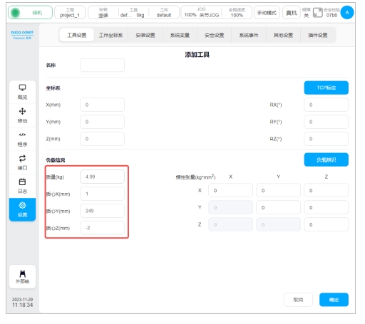
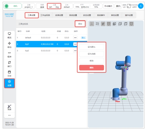
In the robot setting interface - Tool setting interface, you can set the robot tool, add a new tool or click the modify button of the corresponding tool to configure the name, position, quality and centroid parameters of the robot tool coordinate system, as shown in the following figure:
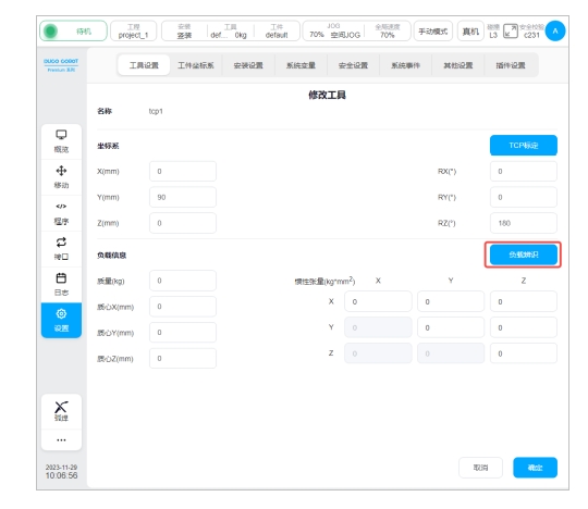
After entering the tool configuration page, click the “Load identification” button to enter the mass center of mass identification function, as shown in the following picture:
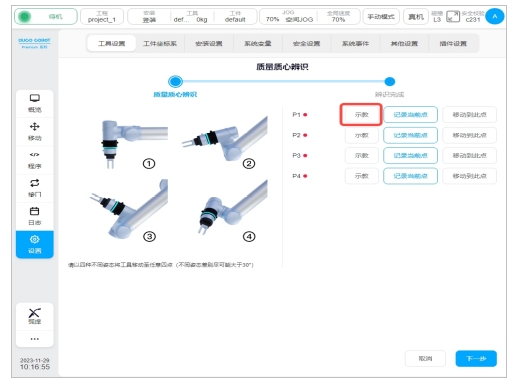
Enter the operation interface of the mass center of mass identification function, as shown in the figure below:
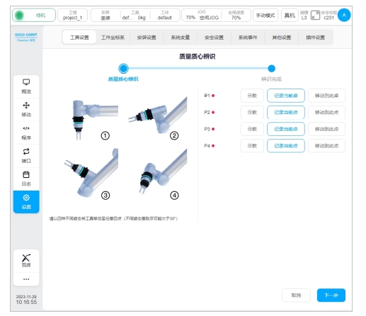
The operation interface contains: identification point setting button, identification point setting indicator light, function exit button and identification calculation button.
Identify point setting#
When using the terminal load identification function, the user should first select 4 identification points, click the “Teach” button in the operation interface, and the interface will jump to the mobile page, as shown in the following figure:
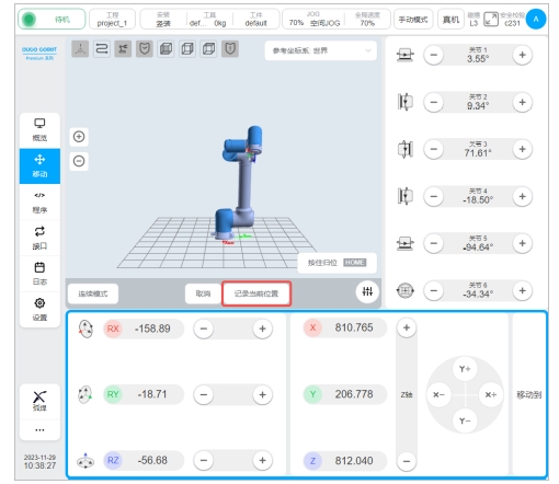
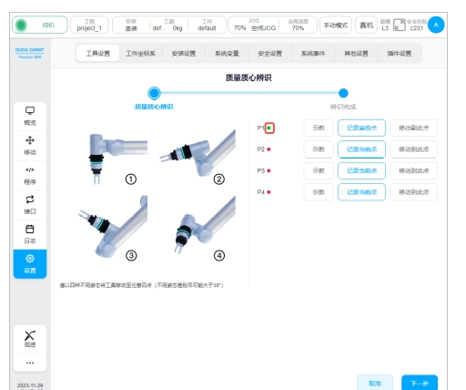
After the mobile robot reaches the target point, click “Record current position”, and the interface will jump back to the interface of mass centroid identification teaching mark point, and after teaching a mark point, the red dot after the corresponding mark point will turn green, as shown in the following figure:
You can also move the robot directly to the target point by pressing the physical button of teach pendant and click “Record current point” directly.
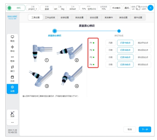
After setting all identification points of P1-P4, click the “Next” button to identify the end load, as shown in the figure below:
The following relationships need to be satisfied between the identification points:
The end posture rotation offset from point to point must be greater than 10°.
There can be no coplane between point and point.
During the teaching process, if the current teaching point does not meet the restrictions, the following message will be displayed:
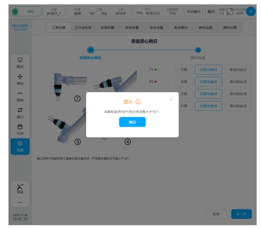
If all the points are coplane, click the “Next” button to perform the identification function, the corresponding error will be feedback, indicating that the user’s identification points violate the above restrictions, and the user needs to modify the corresponding identification points according to the prompt information until the point needs of the end load identification function are met.
indicates that the identification result takes effect#
The identification result will be displayed after all identification points are correctly set and clicked to confirm, as shown below:
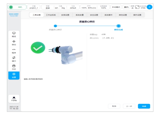
Users can decide whether to use this set of mass and centroid parameters as the current tool setting parameters according to the actual situation. If you choose to use, click the “Finish” button, as shown below: