Introduction#
In welding applications, direct communication between robots and welders is usually required to reduce communication delay and achieve better welding quality. The welding process package is divided into two parts, the setup of the welding machine and the application of welding instructions.
Adaptation Description#
Before the installation of the welding process package, it is necessary to ensure that the software version of the robot matches, specifically:
Robot control software version |
V2.2.1 or later |
Robot slave firmware version |
V1.0.2 and above |
Robot safety controller version |
V2.1.0 and above |
You can query the version information of the robot on the About interface after the robot is powered on. For how to open the “About” interface, see Section 7 of the DUCO CORE- User Manual.
For the welding process package V1.3 and above, the software version of the robot must be V2.7.0 and above
The current version supports the following welding machine models:
Welder manufacturer |
Welder model |
Communication protocol |
|---|---|---|
Megmet |
ArtSet Plus/Pro series |
CAN |
The current version supports laser sensors: Beijing Idea, Tangshan Yinglai, Suzhou Quanvision
Welding Machine Connection#
When using CAN communication, it is necessary to refer to the “Collaborative Robot User Manual (Hardware part)” and the welding machine manual to connect the CAN communication interface of the two. In order to ensure the communication quality, it is usually necessary to parallel a 120Ω terminal resistor at the interface to eliminate signal reflection. Take Magmet ArtSet Plus/Pro series welder as an example:
1、 Query “User Manual of Collaborative Robot (Hardware part)” and find the CAN communication interface, as shown in the following figure:
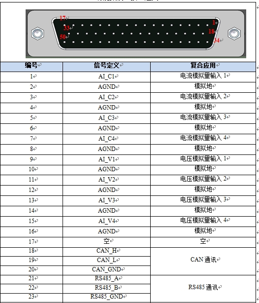
As the table, CAN communication uses pins 18,19,20
2、 query the welding machine manual, find the welding machine side CAN communication interface, as shown in the following figure:
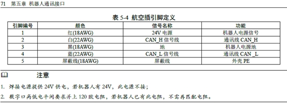
3、 According to the instructions of the robot and welding machine, connect the white wire of the welding machine to the 18th pin of the robot expansion interface, connect the blue wire to the 19th pin of the robot expansion interface, and connect the black wire to the 20th pin of the robot expansion interface.
Process Package Installation and Uninstallation#
The welding process package file is the plug-in of weld.plugin. The installation procedure is as follows:
the welding process package into the U disk, U disk requires FAT32 format
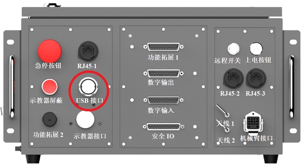
After the robot system is started, insert a U disk into the USB interface on the robot control cabinet.
Log in to the robot system as user admin.
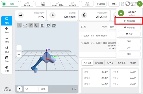
Click the user profile picture
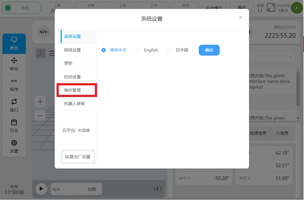
, select System Settings.
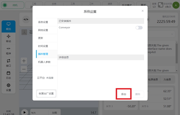
Select the plug-in management function.
Click the Add button.

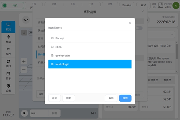
7, select the USB flash drive and from the file list, find and select the weld.plugin package.
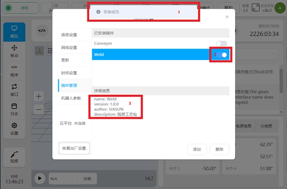
After the plug-in package is installed, will be marked as shown in the following figure. Newly installed plug-in packages will be enabled by default at . displays the name and version of the current plug-in package.
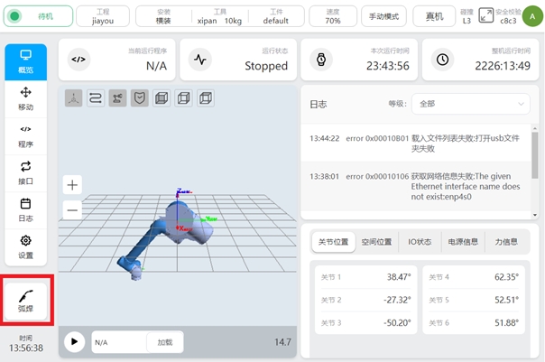
After the welding process package is installed, the process package setting portal will appear at the lower left of the main interface.
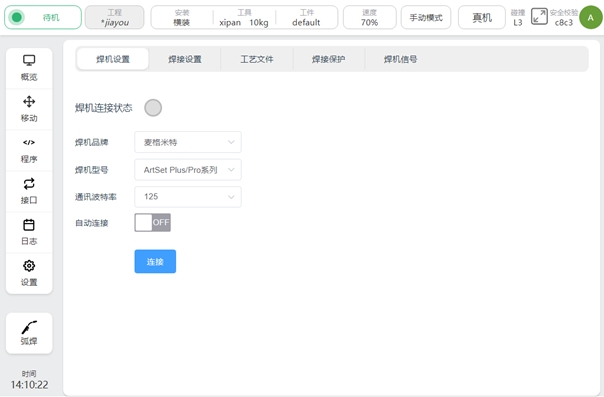
10, click the process package setting entry button, you can enter the welding process package setting interface.
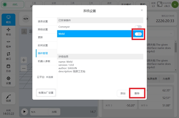
The welding process package that has been installed can be temporarily disabled by turning off the enable signal. Or click the Delete button to delete the package completely.