Laser Tracker#
Introduce#
The laser tracker acquires the characteristics of the weld and identifies the weld by collecting the laser image. The robot acquires the characteristic information it recognizes and realizes the automatic monitoring and correction of the weld. In practical application, it can solve the problems such as the placement error of the workpiece, the poor consistency of the workpiece, and the deformation of the weld caused by welding heat.
The welding process package supports laser locating and laser tracking.
Laser Communication Connection#
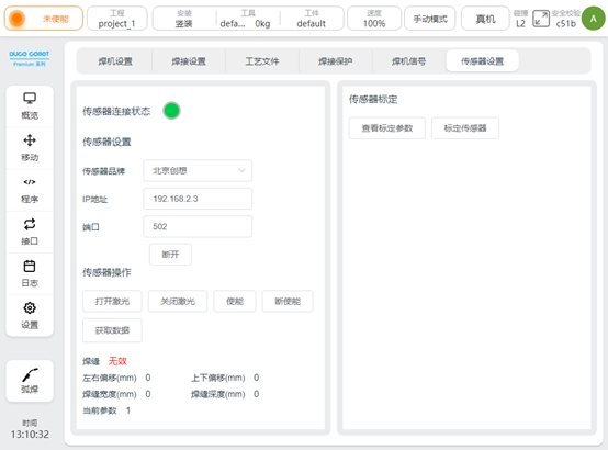
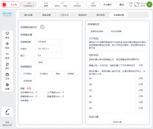
Use a network cable to connect the network port on the robot control cabinet to the laser sensor, and configure the IP address of the robot and the laser sensor to the same network segment. Enter the IP and port number of the laser sensor and click Connect. After the connection is successful, the connection status is displayed. The connection Settings for each manufacturer are as follows
Beijing Creation:
It is necessary to set the laser protocol to Modbus by using the upper computer of the Idea first. Connect to port 502
Tangshan Yinglai:
Set the port number to 5020.
Suzhou Total Vision:
Set the port number to 502
Laser sensor control
You can manually operate the laser sensor, turn the laser on/off, and obtain the data detected by the laser.
Laser Calibration#
The calibration of the laser sensor is used to calculate the position relationship between the robot TCP and the sensor. That is, according to the results of calibration calculation, the feature points identified by the laser can be converted to their pose in the robot coordinate system.
Calibration preparation:
1、 Install the welding gun and adjust the length of the welding wire to the length used in the welding process
2、Install the laser sensor according to the installation requirements of the laser sensor and the site situation
3、 Prepare to calibrate the sharp points used by the robot TCP
4、 prepare the switch and other network equipment to connect the laser sensor, the upper computer used by the laser sensor, the robot, and set them in the same network segment to ensure normal communication
5、make sure that the laser image can be seen on the upper computer of the laser sensor
6、 Verify that the laser switch and data acquisition can work normally in the sensor setting page of the robot welding process package
Calibration process:
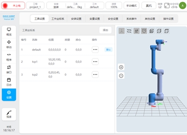
1、the tool (TCP) calibration, that is, the calibration of the end position of the wire, the length of the wire is the length of the actual welding wire. The calibration method is as follows:
In the robot’s Settings page - Tool Settings, create a TCP, according to the 4 point calibration method or 6 point calibration method
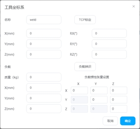


The mobile robot aligns the end of the wire to the cusp point and records the four points respectively
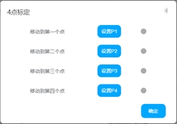
Click OK to calculate the calibrated TCP coordinates and errors. Control the average error and maximum error within 0.5mm.
Set the calibrated TCP to the current TCP
2、 Take a mark point on the weld, move the robot, align its TCP with the mark point, and click Record
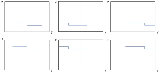
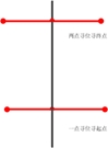
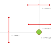
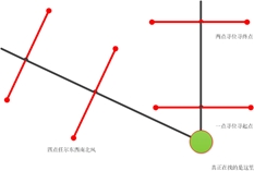
3、 Keep the posture of the robot unchanged, turn on the laser, turn on the enable, move the robot, let the laser fall on the marking point, observe the laser image on the laser software during the marking process, and make the laser image into the six states in the following figure respectively, and record the points 1-6
4、 click calibration calculation, calibration error and calculation results will be displayed below. If each value is less than 1mm, calibration is valid, otherwise re-calibration.
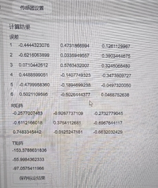
5、 Click Save the calibration result, and the calculation result will be saved after confirmation. Note: The calculation result is stored in the current project of the robot. It is recommended to save the project at this time to prevent loss.
Attention:
1、 Robot TCP needs to be calibrated before calibration to ensure calibration accuracy
2、 Before calibration, set the calibrated tool coordinate system to the current
3、 When recording 7 points, the length of the welding wire is consistent with the calibration TCP, and the length of the welding wire should also be consistent with the welding process
4、 When recording 7 points, the posture of the robot cannot be changed
5、 When recording these 7 points, ensure the stability of laser image detection
Calibration accuracy verification
After the sensor and robot are calibrated, the accuracy of the calibration can be verified using a single point of search. Write the following program using the function blocks LaserSearchPose and MoveL. LaserSearchPose will turn on and enable the laser, obtain the feature point information recognized by the laser, convert it into its value under the robot base marker system, and assign the value to the variable. MoveL moves to this variable. Run the program to check whether the robot TCP has moved to the identified feature points.
Note: Please ensure that the TCP used at this time is the TCP used in the above calibration

Programming Function Block#
There are three functional blocks related to laser sensors: LaserSerachPose, LaserSearchOffset, LaserTrack.
LaserSearchPose
It is mainly used to obtain the pose of the feature points identified by laser in the robot base coordinate system. The function block encapsulates the following operations: select the Job number used, turn on and enable the laser, obtain the feature point position information recognized by the laser, obtain the current TCP value of the robot in the base coordinate system, calculate the pose information of the feature point in the base coordinate system of the robot according to the calibration relationship, and assign the pose type variable. If no weld is detected, return nil The configuration page is as follows
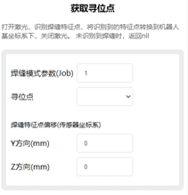
Weld mode parameter: that is, Job number, is a set of parameters set and saved at the end of the laser tracker: such as weld type, exposure, detection capability, etc.
Location-seeking: The result of a calculation that can be associated with a pose type variable
Weld feature point offset: Add the offset to the identified feature point and calculate the pose after the conversion of the offset point. It can be used to deal with problems such as robot error, detection point and welding process mismatch (if the laser tracker provides the function, it can also be set at the laser tracker end)
LaserSearchOffset
It is mainly used to calculate the pose of the coordinate system obtained by three or four point positioning
The configuration page is as follows
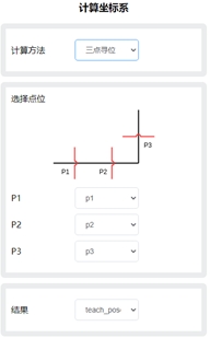
The following Settings are available
Calculation method: Choose three-point or four-point search
Select point: Associates point information
Result: The calculated result, associated with the pose type variable
LaserTrack
Realize laser tracking function.
Main functions: turn on and enable the laser, set the Job number used by the laser, set the compensation direction and advance distance, obtain the weld feature points in real time, calculate the deviation and compensate to the actual trajectory.
The configuration page is as follows
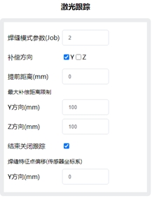
The following Settings are available
Weld mode parameter: Job number
Compensation direction: Select Y or Z direction to enable compensation
Advance distance: Set the distance between the laser wire and the welding torch, in mm.
Maximum compensation distance limit: The maximum allowable deviation between the taught trajectory and the trajectory measured by the laser
Weld feature point offset: The offset is added to the identified feature point (if the laser tracker provides the function, it can also be set at the laser tracker end)
Programming Scripts#
The following script is added to the welding process package, which can be invoked when programming with the script
Turn on the laser
_plugin_weld.open_laser()
Laser off
_plugin_weld.close_laser()
Enable laser (Creative laser sensor needs to be called)
_plugin_weld.enable_laser()
Lower enable laser (Creative laser sensor needs to be called)
_plugin_weld.disable_laser()
Set weld type parameters (Job number)
_plugin_weld.set_laser_weld_type(type)
Position seeking, the function is the same as LaserSearchPose function block, turn on the laser, obtain the weld feature point, calculate its position and pose in the robot coordinate system, and turn off the laser.
_plugin_weld.search_pose(pose, offset)
pose: pose type, robot TCP pose, unit m, rad
offset: specifies the number_list offset of the weld feature points. The value is {y, z}. The default value is {0, 0}, in mm
Returned value
pose type: pose of the feature point in the robot coordinate system. When the unit m, rad, is nil, it means that no weld is detected
Similar to search_pose, the laser is not switched on and off, the weld feature points are obtained, and the pose in the robot coordinate system is calculated
_plugin_weld. get_laser_search_pose(pose, offset)
pose: pose type, robot TCP pose, unit m, rad
offset: specifies the number_list offset of the weld feature points. The value is {y, z}. The default value is {0, 0}, in mm
Returned value pose type: pose of the feature point in the robot coordinate system. When the unit m, rad, is nil, it means that no weld is detected
Obtain raw laser data
_plugin_weld.get_laser_raw_data()
Return the following array {status, y, z, width, depth}, respectively
status: boolean Indicates whether a weld is detected
y: number indicates the y-direction coordinate of the weld feature point (unit: mm)
z: number indicates the z-direction coordinate of the weld feature point, in mm
width: number, the width of the detected weld, in mm
depth: number: depth of the detected weld (unit: mm)
Laser Locating#
Single point search
Suitable for spot welding and other scenarios
A programming example is as follows:
Two-point search
Suitable for intermittent short welding and other scenarios
Programming example is as follows
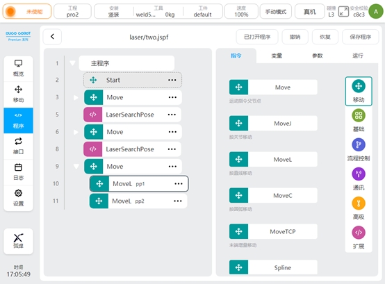
Three-point search/four-point search
The basic principle is: a workpiece coordinate system is established according to the point position of laser locating, and the deviation between it and the original workpiece coordinate system is calculated, so as to obtain the offset of the weld on the workpiece. It can be used for welding of complex structural parts. Compared with three-point locating, four-point locating can better deal with the incoming material error and assembly error of the workpiece.
The following is a Demo of three-point search, four-point search is similar to three-point search.
Variable definition
Variable name |
type |
|
|---|---|---|
P1 |
pose |
The first search site obtained |
P2 |
pose |
The second seek site obtained |
P3 |
pose |
The third search site obtained |
teach_pose |
pose |
The result of three point search calculation |
g_enable_offset |
boolean |
Control program operation. When false, it is used to calculate the initial workpiece coordinate system for the first search; If the value is true, the normal job process is performed |
g_base_pose |
pose |
Calculated initial workpiece coordinate system |
g_pose |
pose |
The result of three search calculations |
g_offset |
pose |
Deviation from the initial coordinate system |
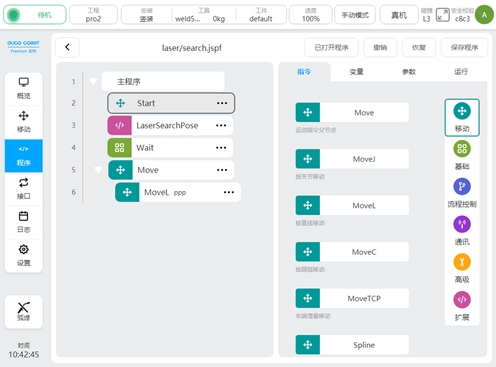
Program specification
The first search point in line 3
Line 5 search, get the search result, save in variable p1
Line 6 second search point
Search for 8 lines, obtain the search result, and save it in variable p2
Line 9 third search site
Search in line 11 to obtain the search result and save it in variable p3
12 lines of three-point search, calculate p1,p2,p3 determined coordinate system, save in variable teach_pose
If g_enable_offse is false, assign the teach_pose value to g_base_pose. Otherwise, the value is assigned to the variable g_pose
Line 17 Perform subsequent operations when g_enable_offset is set to true
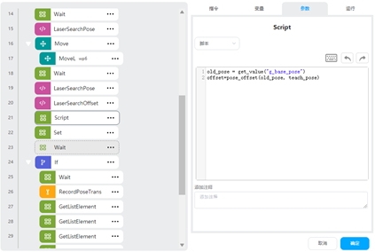
The script in line 18 uses pose_offset() to calculate the coordinate deviation of g_base_pose and g_pose and assigns the result to the variable g_offset
Line 20 adds g_offset as a coordinate offset to the current coordinate system
21-24 lines of actual work points, using the workpiece coordinate system.
The actual use process is as follows: 1、 teach the robot, determine the laser search point
2、 Set the workpiece, set g_enable_offset to false, and run the program
3、 View the value of g_base_pose in the variables area and create a new workpiece coordinate system wobj1, which uses the value of g_base_pose
4、 Set wobj1 as the current workpiece coordinate system, and use this coordinate system as the reference to show the work track of the teaching workpiece, that is, the point position of lines 22-24
5、 Set g_enable_offset to true, run the program, and execute the normal job flow.
The above Demo uses the workpiece coordinate system, and obtains an initial workpiece coordinate system by performing the three-point search calculation for the first time, based on which the teaching operation point is shown. Ensure that if the workpiece has a certain deviation due to placement, you can calculate the deviation of the coordinate system obtained by three-point positioning and the initial coordinate system, and add the deviation to the workpiece coordinate system, so that the operation trajectory can adapt to the change.
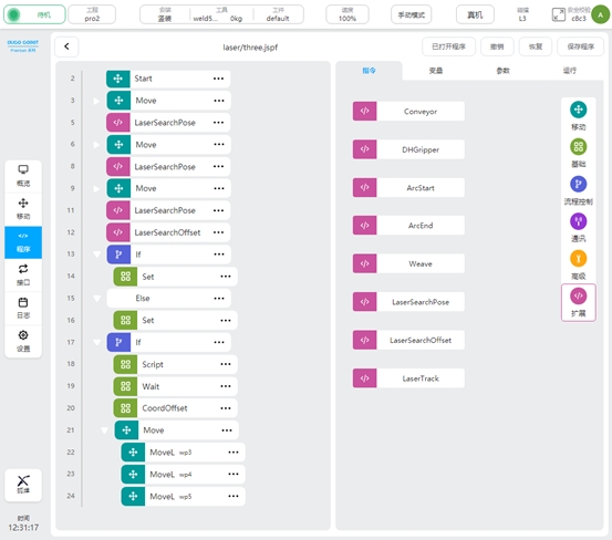
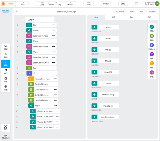
Because the Demo needs to set the coordinate system of the workpiece, in some cases, the teaching needs to change the coordinate system frequently, which may be complicated. You can refer to the following Demo, using the RecordPoseTrans function block, you can be based on the base coordinate system programming.
Variable definition
Variable name |
type |
|
|---|---|---|
P1 |
pose |
The first search site obtained |
P2 |
pose |
The second seek site obtained |
P3 |
pose |
The third search site obtained |
teach_pose |
pose |
The result of three point search calculation |
g_enable_offset |
boolean |
Control program operation. When false, it is used to calculate the initial workpiece coordinate system for the first search; If the value is true, the normal job process is performed |
g_base_pose |
pose |
Coordinate system for three-point homing calculation |
g_result_list |
pose_list |
The pose of the actual operation point in the base coordinate system |
g_way_pose1 |
pose |
The first operation point |
g_way_pose2 |
pose |
Second operation point |
g_way_pose3 |
pose |
The third operation point |
g_way_pose4 |
pose |
The fourth operation point |
Program specification
The first search point in line 3
Line 5 search, get the search result, save in variable p1
Line 6 second search point
Search for 8 lines, obtain the search result, and save it in variable p2
Line 9 third search site
Search in line 11 to obtain the search result and save it in variable p3
12 lines of three-point search, calculate p1,p2,p3 determined coordinate system, save in variable teach_pose
Line 13 assigns the teach_pose value to g_pose
Line 14 Perform subsequent operations when g_enable_offset is set to true
15 lines of action point to teach the transformation and save the results in the variable g_result_list
Lines 16-19 get the points from the g_result_list and assign them to the job point variables
Lines 20-24 perform the actual job, the point using the individual job point variables
The actual use process is as follows:
1、 teach the robot, determine the laser search point
2、 Set the workpiece, set g_enable_offset to false, and run the program
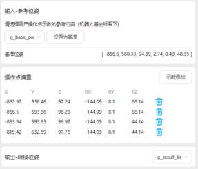
3、 Check the value of g_base_pose in the variable area and open the RecordPoseTrans function block, as shown in the figure. Select variable g_base_pose from the input reference pose and click the “Set as baseline” button,the baseline pose value is displayed on the baseline pose.
4、 In the operation point bias, teach to add job points, and select a pose_list variable in the output to store the calculated job points results
5、Set g_enable_offset to true, run the program, and execute the normal job flow.
Compared with the previous Demo, the variables are used as the actual job points, and the points are calculated through RecordPoseTrans. Use the coordinate system obtained for the first time as the benchmark to teach each job point and add it to the RecordPoseTrans block. Subsequently, if the workpiece is offset, the RecordPoseTrans function block is used to calculate the value of each operation point in the base coordinate system according to the coordinate system calculated by searching.
Laser Tracking#
When it is necessary to detect changes in the weld in real time during the welding process, the laser tracking function is needed at this time.
The following example
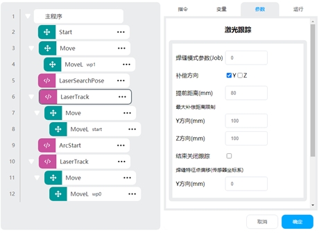
Program specification
In line 4, the robot opens the tracking point wp1
5 line start point search, put the result in the variable start
Line 6 Enables tracing and does not disable tracing at the end of setting
7 rows move to the starting point
9 Line arcing
Line 10 Turn on tracing and turn off tracing at the end of setting
The 11 lines teach a primitive track wp0
The robot will perform the following operations: turn on and enable the laser to obtain the arc starting point, turn on the tracking and move to the arc starting point, turn on the arc starting, turn on the tracking, calculate the deviation from the teaching trajectory according to the real-time acquisition of the feature points obtained by the laser sensor, and compensate the deviation to the teaching trajectory, so that the robot TCP can operate according to the detected weld.
Exception Detection#
Weld detection
LaserSearchPose can determine whether the return value is nil to determine whether the weld is detected. An example is as follows:
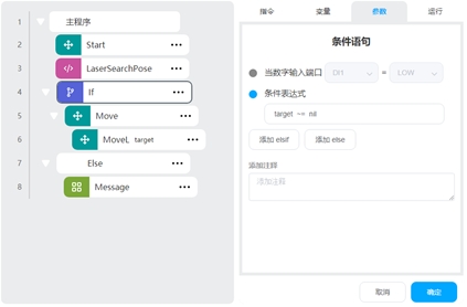
LaserSearchPose puts the search result in the variable target, and the If condition determines whether target is nil to perform the logic when the weld is detected and when the weld is not detected
Three/four point seeking deviation too large protection
In some cases, the weld may be detected incorrectly, resulting in excessive deviation of the calculated workpiece coordinate system, which can increase the deviation limit to prevent safety problems such as gun bump.
An example is as follows:
The Script function block uses the pose_offset script to calculate the deviation of the original and new calculated coordinate systems, adding execution logic that determines that the deviation is greater than a certain range.