Welding Applications#
Arc Starting Conditions#
The robot sends the arc signal to the welding machine, which needs to meet four necessary conditions:
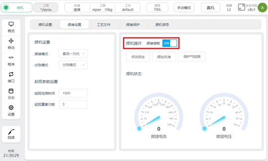
1、welding enable signal open
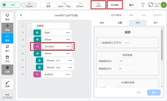
2、 the robot movement mode is automatic mode
3、 The robot’s global speed is set to 100%
4、 in the robot script, there is an arc script
Arc Starting and Ending Function Blocks#
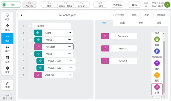
After the welding process package is installed and the plug-in package is enabled, two new program function blocks ArcStart and ArcEnd will be added in the extension function script bar of the robot program interface.
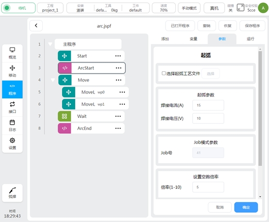
The arc starting/closing block allows the arc starting/closing instructions to be sent to the welder in three different modes. They are the methods of calling the process file, setting the arc starting parameter, and setting the JOB number. In the arc starting function block, the magnification can also be set during idle running, so that the robot can run at high speed when the welding function is not enabled, so as to quickly observe the correctness of the welding trajectory during debugging. In the welding process, it is necessary to change the welding parameters during the operation of the robot, which can be achieved by setting two arcstarts.
Select arcing/closing process file:
When selecting process files, ensure that the welder control mode is DC unified, see the welding Settings section for details. Check the check box first when using, as shown below:
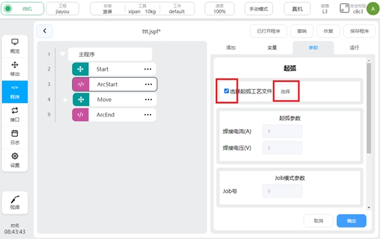
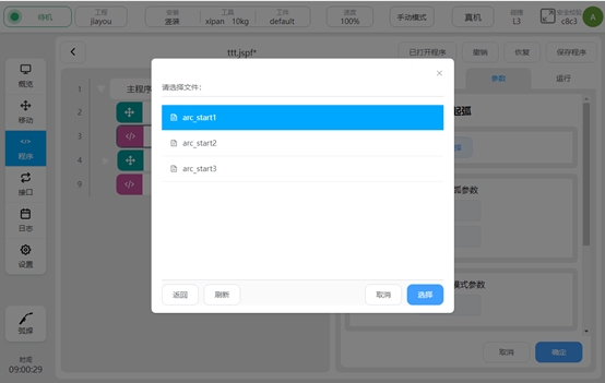
When the check box is displayed, the parameters in arc starting parameters and Job mode parameters become gray and cannot be edited. Click “Select” to select the process file, as shown in the picture below:
After the process file is selected, the welding parameters in the process file will be displayed in the gray arcing parameters, and the parameter units are related to the respective modes set. As shown in the picture below:
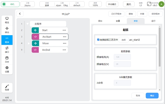
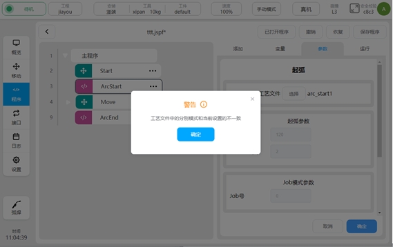
If the selected process file has a different mode from the currently set mode, a pop-up will remind you.
Arcing/closing parameters:
When choosing arcing/arcing, ensure that the control mode of the welder is DC unified. For details, see the Welding Settings section. The process file check box cannot be selected, and the Job mode parameters are gray and cannot be edited. Parameter units are related to the respective modes set.
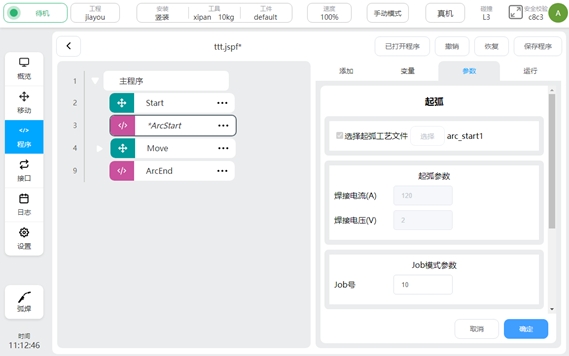
Job mode parameters:
When selecting the Job mode parameter, ensure that the welder control mode is Job mode. For details, see Welding Settings. When the parameter is set to Job mode, the process file and arc starting parameters are gray and cannot be edited.
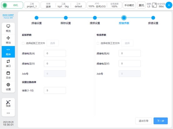
Set the empty run ratio:
After the empty run ratio is set, when the empty run function is turned on and the welder enable is turned off in the welding setting, all robot motion scripts between ArcStart and ArcEnd will be run at a rate of magnification. The actual speed of the robot will be multiplied by the set multiplier. The calculation formula is:
Actual operating speed = set welding speed * Manual/automatic reduction ratio * Global speed * magnification
For example, set the welding speed to 20mm/s, set the global speed to 70% in manual mode, and set the idle speed to 3:
Among them, the manual reduction ratio is 25%, and the automatic reduction ratio is 100%.
Actual operating speed =10.5mm/s.
For example, the welding speed is set to 20mm/s, the global speed is set to 80% in automatic mode, and the idle speed is set to 3:
Among them, the manual reduction ratio is 25%, and the automatic reduction ratio is 100%.
Actual running speed =42mm/s.
Swing Welding#
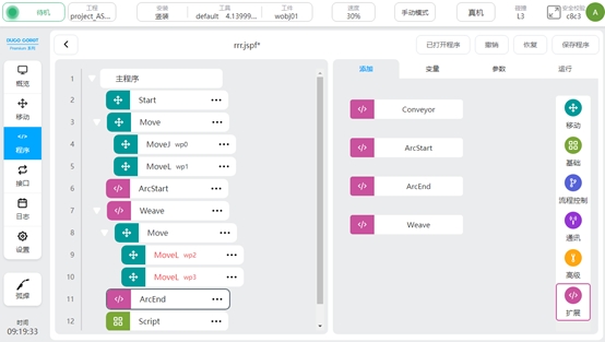
Welding process package V1.2.0 and above, adding pendulum welding function. In the “Extension” instruction set in the programming interface, call the “weave” function block to enable the swing welding function. As shown in the picture above.
Usually, when the swing welding function is used, it is programmed to add a swing welding function block (Weave) behind the original ArcStart function block. Then in weave, add trajectories that need to be wobbled. All motion instructions added in weave will have a wiggling motion effect until the motion instructions are complete.
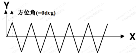
The business logic of pendulum welding is to superimpose a layer of periodic and regular swing trajectory on the basis of the original motion trajectory. In the current version, the azimuth is 0° by default and cannot be set. As shown in the picture above.
Click the weave feature block to set the weave trajectory. The parameters that can be set are: track type, reference plane, frequency amplitude. When selecting a trapezoidal trajectory, the left and right residence time parameters need to be added.
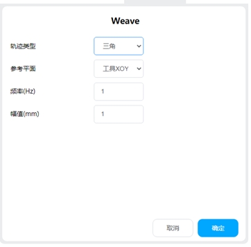
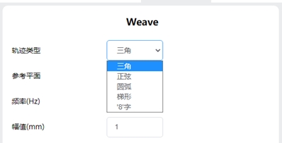
Track type:
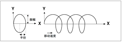
Support the following types, triangle, sine, arc, trapezoid, 8-word
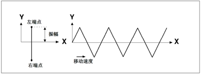
Triangular trajectory: Standard swing welding mode. It is usually used in scenarios with large welds and multi-layer welding.
Sinusoidal trajectory: Standard swing welding mode. It is usually used in scenarios with large welds and multi-layer welding.
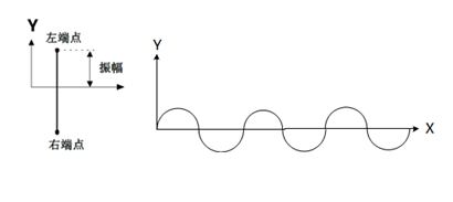
For a sinusoidal trajectory, the residence time of the left and right endpoints can be set
Arc track: mainly used in lap joints and welding with large caps. The radius of the circle is the same as the amplitude.
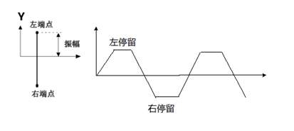
Trapezoidal trajectory: Standard swing welding mode. It is usually used in scenarios with large welds and multi-layer welding.
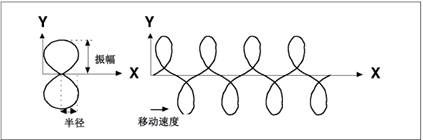
“8” word track: mainly in thick plate welding and surface/exterior grinding, improving strength and other applications.
Reference plane:
With the current tool coordinate system as reference, set the plane where the swing trajectory takes effect. Supports XOY, XOZ, and YOZ planes.
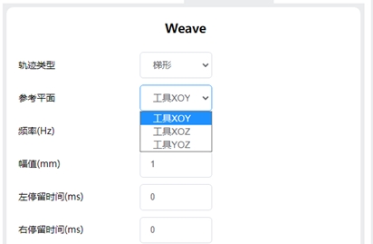
Frequency: The number of cycles performed per second by the swing trajectory.
Amplitude: The boundary of the swing trajectory deviates from the maximum value of the reference trajectory.
Left and right residence time: Used to define the length of the upper and lower sides of a trapezoidal or sinusoidal trajectory.
Left endpoint OP: When swinging to the left end point, the action performed: controls the DO status and duration or triggers the event
Right endpoint OP: Action performed when the swing reaches the right endpoint: controls the DO status and duration or triggers an event
Left to right middle point OP: Action performed when the swing moves from the left endpoint to the right endpoint, passing the intermediate point: controls the DO status and duration or triggers an event
Right to left middle point OP: Action performed when the swing moves from the right endpoint to the left endpoint, passing the intermediate point: controls the DO status and duration or triggers an event
Custom Swing Welding#
Welding process package V1.4 and above, DUCO Core v2.9.0 and above Custom swing welding, that is, the user can customize the trajectory of the swing welding In the process file, create a custom swing welding track file and set a custom track point
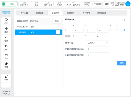
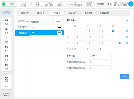
A maximum of 10 pendulum solder joint positions can be set. Point configuration parameters include X: The direction along the tangent line of the trajectory Y: The direction determined by Z and X cross Z: The direction in the reference plane perpendicular to the tangent line of the trajectory R: indicates whether the endpoint is a right endpoint L: indicates whether the endpoint is a left endpoint When setting, ensure that the sum of each point in the X, Y, and Z directions is 0
Reference plane: Select a plane of the tool coordinate system as the reference plane of the swing Left endpoint residence time: Residence time of the left endpoint
Right endpoint residence time: Residence time of the right endpoint
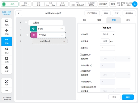
In the Weave block, select the track type as Custom and select the track file.
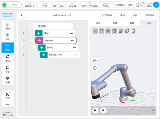
You can simulate running trajectories
Arc Tracking#
Welding process package V1.4 and above, DUCO Core v2.9.0 and above Arc tracking is mainly used in the welding of thick plate. In the welding process, the current flow between the welding wire and the workpiece is detected to compensate the welding trajectory of the robot.
Only the up and down direction and the left and right direction can be compensated, and the left and right direction can be compensated only in the sine type swing welding.
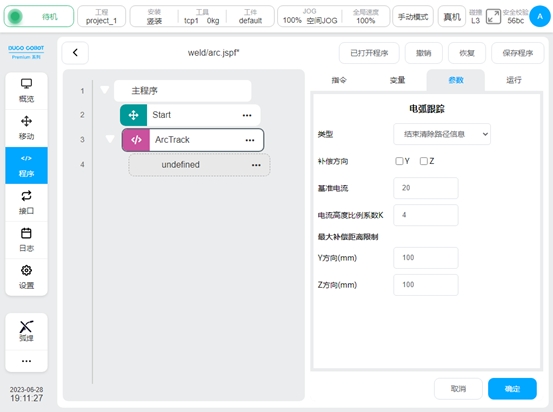
Arc tracking command: ArcTrack
The configuration parameters are as follows:
Type: Used to set the arc tracking type, with the following options:
End Clear path information. The offset information is cleared when the tracing is complete
End The path information is retained, and the offset information is retained when the tracing ends
Use the recorded path information, use the offset information of the last tracking record to track (mainly used for multi-layer multi-pass welding)
Compensation direction: Select the direction where the compensation function is enabled, Y (left and right direction), Z (up and down direction). You can choose to enable Y and Z compensation for sine pendulum welding, other types can only enable Z compensation
Reference current: reference current value
Ratio coefficient of current height: Ratio coefficient of welding current to welding gun height, default value 4
Maximum compensation distance limit: The maximum allowable deviation distance of the left and right direction and the up and down direction relative to the teaching trajectory
Multi-layer Multi-pass Welding#
Welding process package V1.4 and above, DUCO Core v2.9.0 and above
The welding of medium and thick plates often requires multiple welding of the same part to increase the welding width. The main principle is: record the track of the first weld and the compensation amount; Based on the recorded amount of compensation, the overall offset is added to achieve subsequent pass operations.
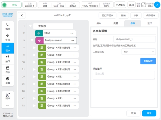
This process package provides a MultipassWeld function block to guide the user through the programming of a multipass welding job.
In the programming page instruction “Extend”, look for the “MultipassWeld” function block. Add it to the program, click, the configuration page is as follows
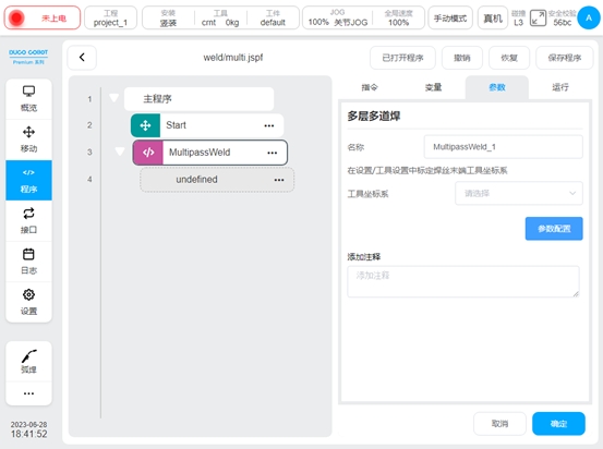
Configure the tool coordinate system: Use the end of the wire to show the tool coordinate system in the Settings page
Click Parameter configuration to enter the multi-layer and multi-pass welding boot configuration page. It is divided into the following steps, click next or click the navigation menu above to switch.
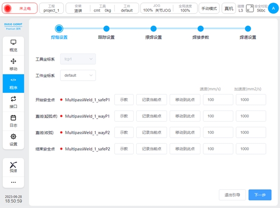
Weld configuration
Configure the point position of the initial weld, mainly configure the workpiece coordinate system, the beginning safety point, the starting point, the end point and the end safety point of the weld. It can teach the point coordinates and speed and acceleration of each point.

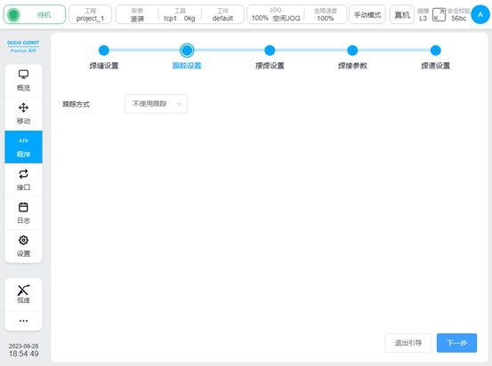
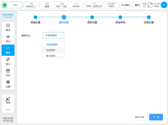
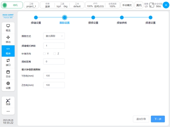
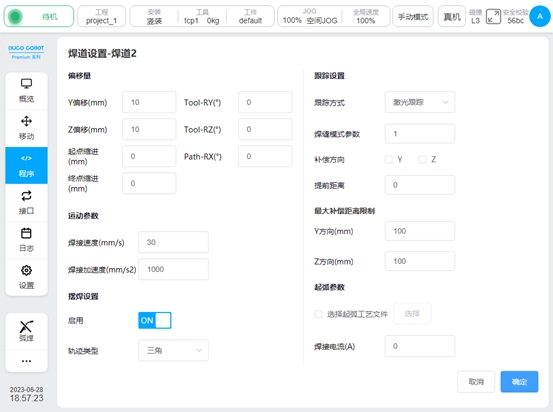
Tracking Settings
Configure whether the weld uses tracking, you can choose not to use tracking, use arc tracking, use laser tracking. When selecting arc tracking, see Section 5.4 “Arc Tracking” for configuration parameters, and Section 7.7 “Laser Tracking” for configuration parameters.
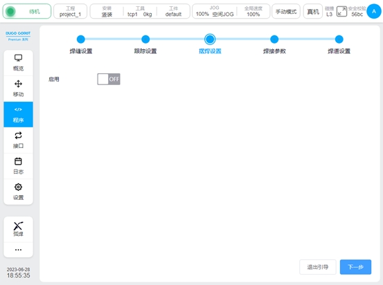
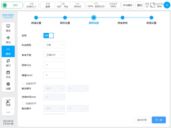
Swing welding Settings
Select whether to enable swing welding and set the type, reference plane, frequency, amplitude, OP, etc. For details about the configuration parameters, see Section 5.3 “Swing Welding”.
Welding parameters
Set welding parameters, such as welding current, voltage, and JOB number. For details about the configuration parameters, see section 5.2 “Arc Starting/Closing Function Block”.
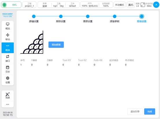
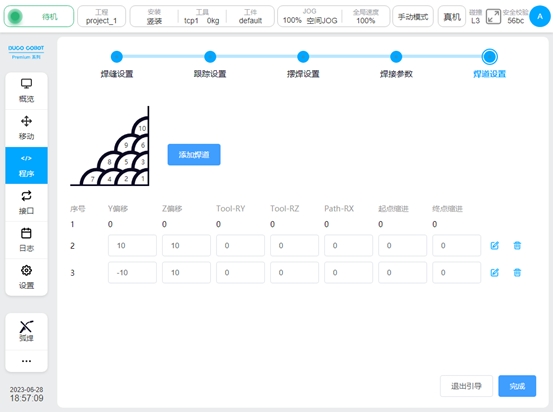
Bead setting
Configure the offset, indent, tool posture, etc., for each subsequent pass, up to 9 passes can be added.
The parameters of the bead are:
Y offset: Y of the tool coordinate system
Z shift:
Tool-ry: indicates the rotation in the Y direction of the Tool reference coordinate system
Tool-rz: The rotation in the Z direction of the Tool reference coordinate system
Path-rx: The rotation of the Path tangent at the start of the tool’s reference path coordinate system (for a straight line, the rotation in the direction of the reference path)
Start indent: The distance from the start of the weld to the path direction
End indent: The distance by which the end of the weld is indent along the path direction
The default swing welding parameters and welding parameters of each weld pass are the same as those of the initial weld. Individual pass parameters can be set individually by clicking the Edit button
Bead detailed configuration
After the configuration is complete, click OK to automatically generate the program block. Note: The generated block cannot edit the parameters separately, if you need to change the parameters, please set them in the parameter configuration of the MultipassWeld block.