Welding package Settings#
Welding process package Settings, including welding machine Settings, welding Settings, process files, welding protection, welding machine signals.
Welder Settings#
Welder Settings Used to display communication status, configure the welder model and corresponding communication Settings.
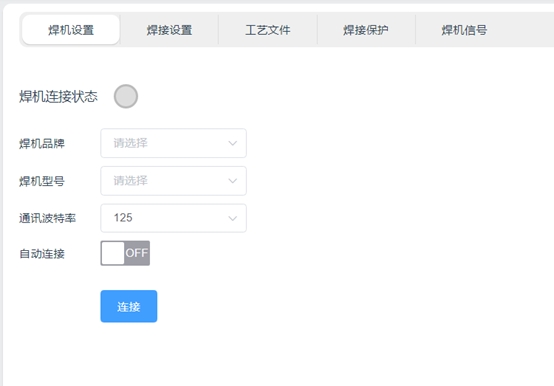
Welding machine connection status: When the communication between the robot and the welding machine is established, the status indicator will turn from gray to green. As shown in the picture below:
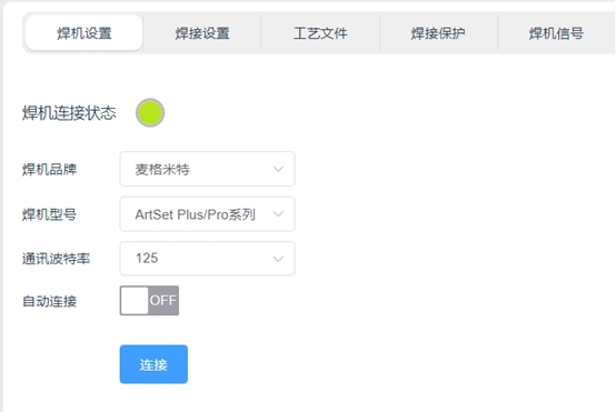
Welder brand and model: Used to configure the current welding machine. After selecting the welder correctly, the robot will invoke the corresponding communication protocol.
On the welding machine side, it is necessary to refer to the welding machine manual, adjust the control mode of the welding machine to the robot control mode, and select the corresponding communication protocol. Take Magmet ArtSet Plus/Pro series welder as an example:
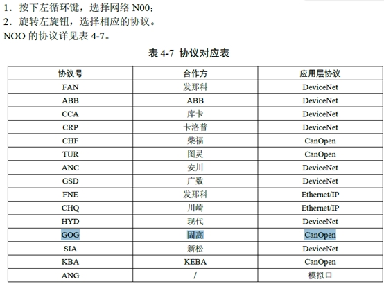
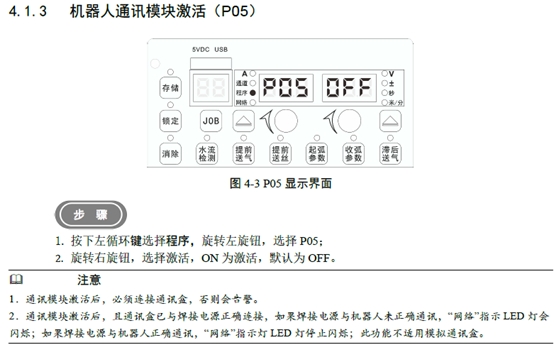
The communication protocol of the welding machine needs to be modulated to GOG mode, and the N00 parameter is set to GOG. At the same time, the function of the robot communication module is activated, and the P05 parameter is set to On.
Communication baud rate: Used to set the baud rate of CAN communication, supporting 125kbps, 250kbps, 500kbps three baud rates. It should be noted that the baud rate of the robot and the welding machine needs to be set consistent in order to achieve communication. Take Magmet ArtSet Plus/Pro series welder as an example:
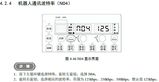
The baud rate of the welder N04 parameter should be consistent with that of the robot.
Automatic connection: It is used to automatically connect the welding machine when the robot starts up next time. When it is set to ON, the robot will save the current setting information, and the next time the robot starts up, it will automatically connect the welding machine after the robot completes the power-on operation of the robot.
Connection: The “Connect” button is usually used when the robot communicates with the welding machine for the first time. Click the “Connect” button to send a connection request to the welder according to the message format of the welder. After receiving the correct feedback from the welder, the welder connection status light turns green.
Welding Settings#
Welding Settings used to set welding mode, arc parameters, manual debugging function of the welder trigger and current and voltage display of the welder.
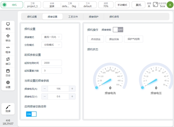
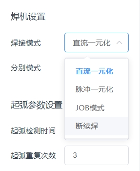
Welding mode: used to set the working mode of the welding machine. When setting, the corresponding communication data will be sent to the welding machine to switch the operating mode. It should be noted that whether the setting can be successful also depends on whether the communication protocol of the welder supports modification. If the communication protocol of the welder does not support it, the same setting needs to be performed manually on the side of the welder. The welder mode that can be set is shown in the following figure:
Take Magmet ArtSet Plus/Pro series welder as an example:
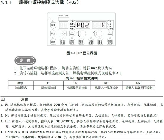
If the DC unified mode is used, in addition to selecting the DC unified mode on the robot side, the P02 parameter needs to be set to DF on the welder side. If the JOB mode is used, set this parameter to DN. At present, the communication protocol does not support pulse unified and intermittent welding, so it is necessary to save the pulse unified parameters or intermittent welding parameters in JOB mode at the welder side, and then invoke the robot in JOB mode to realize the corresponding welding mode.
Separate mode: This parameter is used to set the current and voltage parameter setting mode of the welding machine. It supports separate mode and unified mode. As shown in the picture below:
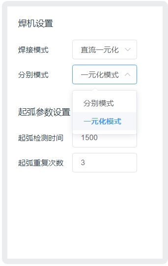
When using separate modes, the unit of current is A and the unit of voltage is V. When using the unified mode, the unit of current is A and the unit of voltage is %. The setting of this parameter will affect the welding voltage unit of the current welding parameters, process files, welding machine signal interface and arc starting/closing parameters in the program script.
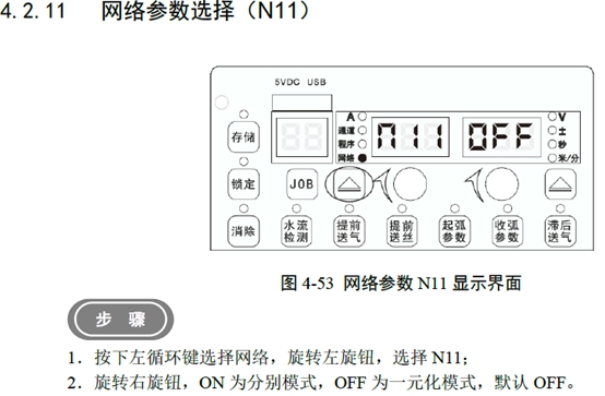
Taking the adaptation of Magmet ArtSet Plus/Pro series welder as an example, it is also necessary to set the N11 parameters on the side of the welder, as shown in the following figure:
Arcing Settings: You can set the arcing detection time and the number of arcing repeats. The unit of arcing detection time is ms. After sending the arcing command, the robot will monitor the successful arcing signal returned by the welder. If the successful arcing signal is not received within the detection time, the arcing command will be re-sent. The number of repetitions is set by the number of arc-starting repetitions.
Currently set welding parameters: change the current and voltage value of the welder in real time. It is usually used in the test welding stage to adjust the current and voltage to find the combination of parameters in line with the process. The set of parameters are the current and voltage parameters actually sent to the welder at present, and have nothing to do with the set values in the program script and process file. For example, after ArcStart is run, this value becomes the parameter set by the ArcStart function block.
Welding idle rate: Enable button for welding idle function. After the function is enabled, when the welder is not enabled, the robot is allowed to run at double speed to quickly observe the correctness of the welding trajectory. The magnification is set in the welding program script.
Welder enable: The enable signal of the arc starting function of the welder. If off, the arcing command will no longer be executed when the robot program is run.
Point wire feeding: button long press trigger, control wire feeding machine, button release will stop wire feeding.
Welding wire reverse pumping: the button is triggered by long press to control the wire feed machine, and the button is released to stop the wire.
Protection gas detection: control the welding machine air valve open, used to test whether the normal gas supply. Taking Magmet ArtSet Plus/Pro series welder as an example, the air valve will be automatically closed by the welder after opening 30 seconds. If you click again midway, turn off the air valve.
Welder status: real-time display of welder feedback welding current and welding voltage. The unit of welding current is A, and the unit of welding voltage is V.
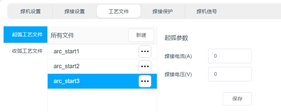
Process Document#
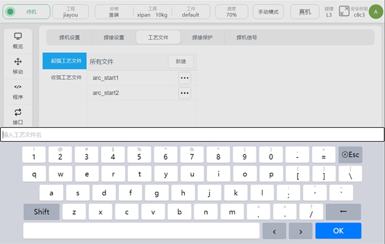
Process files for setting and saving welding currents and voltages for starting and closing arcing. Click “arcing process file” and “arcing process file” to switch process file types. Click “New” to create a process file of the corresponding type. Enter the process file name and click “OK” button to complete the new process file.
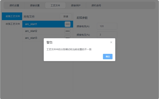
Click File, the input box of welding current and welding voltage will be displayed on the right side. The unit of welding current is A, and the unit of welding voltage will be determined by the setting of the respective mode. See the respective mode Settings. Click “Save” to record the welding current value, welding voltage value and the mode type set during the setting.
If the current welding separate mode Settings are inconsistent with the separate mode Settings selected during process file generation, a pop-up will remind you. As shown in the picture below:
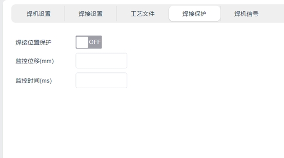
Welding Protection#
Welding protection is the protection function in the welding process, the principle is:
Real-time monitoring of the tool end of the robot whether there is more than the monitoring displacement. If the end of the tool of the robot does not produce enough displacement within the set monitoring time, it is judged that the robot is in the same position, and the arc closing command of the welder will be triggered. The purpose of this function is not to allow the robot to have a long welding operation in the same position, in case the weldment burns through.
Welder Signal#
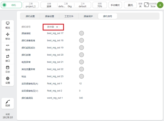
The welding machine signal page is used to display the welding machine signal, and configure the signal to the register, so that the upper controller of the robot can obtain the welding machine information through profinet, modbus, TCP/IP and other ways. tap  to perform register configuration, and a list of configurable registers will be displayed on the right side of the signal, as shown below:
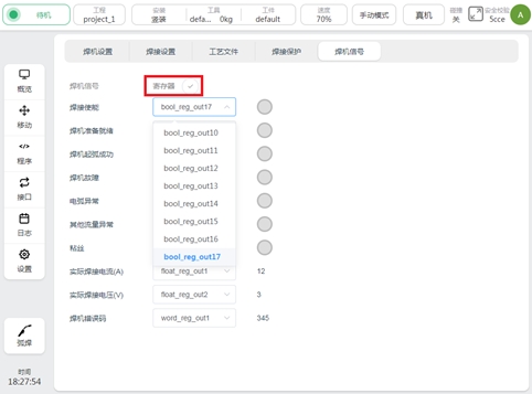
Once the register configuration is complete, click  to save the configuration.
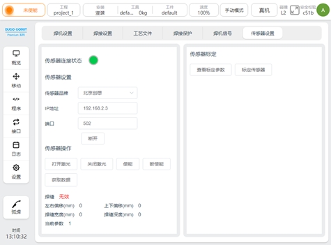
Sensor Settings#
The Sensor Settings page is used to set the laser sensor manufacturer, connection sensor, control sensor, and calibration sensor. In the figure, the left area is used for sensor connection and operation, and the right area is used for viewing calibration parameters and calibration of the laser sensor. See Section 7 Laser Tracker for specific use