Software Operation Guide#
Engineering Management#
Open DUCOMIND Webpage: If the controller’s IP address is known, you can open the DUCOMIND webpage on another laptop or computer as long as this device’s network is set to the same subnet as the controller’s IP. For example, if the controller’s IP is 192.168.3.10, then access 192.168.3.10:7300.
Create New Project#
Click File->Create New Project.
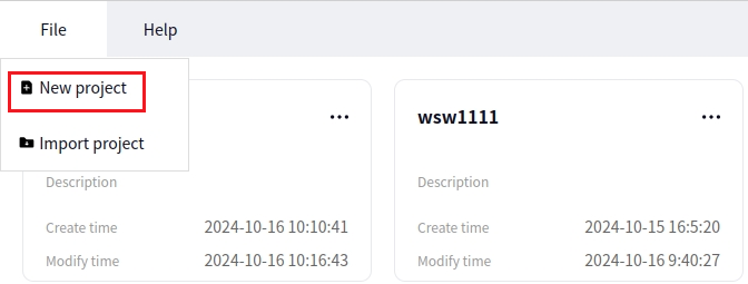
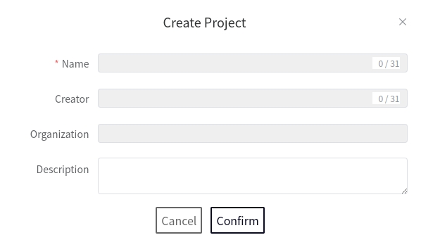
Configure the following in the pop-up dialog box:
- Project Name
Describe the project name, must be unique, mandatory.
- Creator
Enter the creator’s name.
- Organization Name
Enter the organization’s name.
- Project Description
Enter the project description text.
Caution
The project name should comply with the format specifications.
Click Confirm to create a new project or Cancel to cancel the creation.
Open Project#
After clicking on the project you want to open, the word Open will be displayed on it. Click Open to proceed.
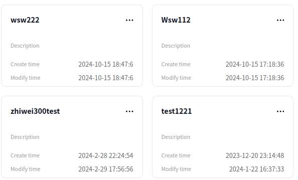
As shown in the above image, there are four projects locally. When you click on the project Test01 with your mouse, the Open word will appear.
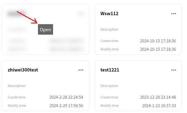
Click Open to open the project Test01.
Process Management#
Create New Process#
Click the Resource->Process and then the + sign to create a new process, as shown in the figure below
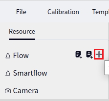
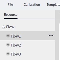
The name of the first newly created process defaults to Process1. Continuing to click the ‘+’ sign will automatically increment the process name. The figure below shows the result after creating three times
Process Configuration#
Change Process Name#
Select the process you need to rename with the mouse, and then click the Second Icon, as shown in the figure below:
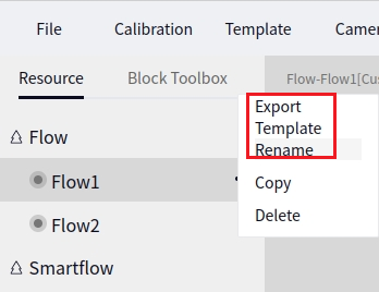
A pop-up window will appear as shown below; enter the new name in the input box
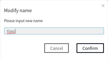
Tip
You cannot enter a name that already exists, and invalid names will prompt a message.
Delete Process#
Select the process you need to delete with the mouse, then click the Third Icon, and finally click Confirm in the pop-up confirmation box to delete the process:
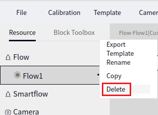
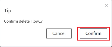
Caution
Once deleted, the process cannot be recovered. Please save any necessary data before deleting.
Process Operation Configuration#
Operation Configuration#
Clicking on a process will bring up the following interface:
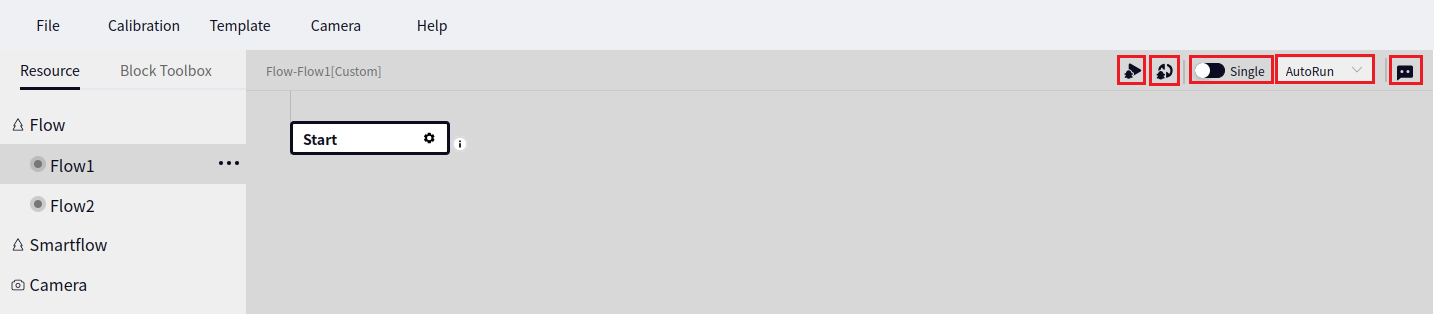
The five icons marked with red boxes in the upper right corner, from left to right, respectively represent:
The first icon is for running the process once
The second icon is for running the process in a loop
The third icon is for the trigger mode operation button, which can be selected for single run or loop run
Tip
The loop run will only be effective when the current process operation mode is set to trigger mode.
The fourth icon is the process operation mode selection box, and you can choose Auto Run, Trigger Mode, or Disable
Tip
Auto Run means the process can be manually run, but not by Event Response;
Trigger Mode means the process can be run by Event Response;
Disable means the process is disabled;
The fifth icon is to add a description or remark to the current process, which can be added by clicking.
Start Configuration#
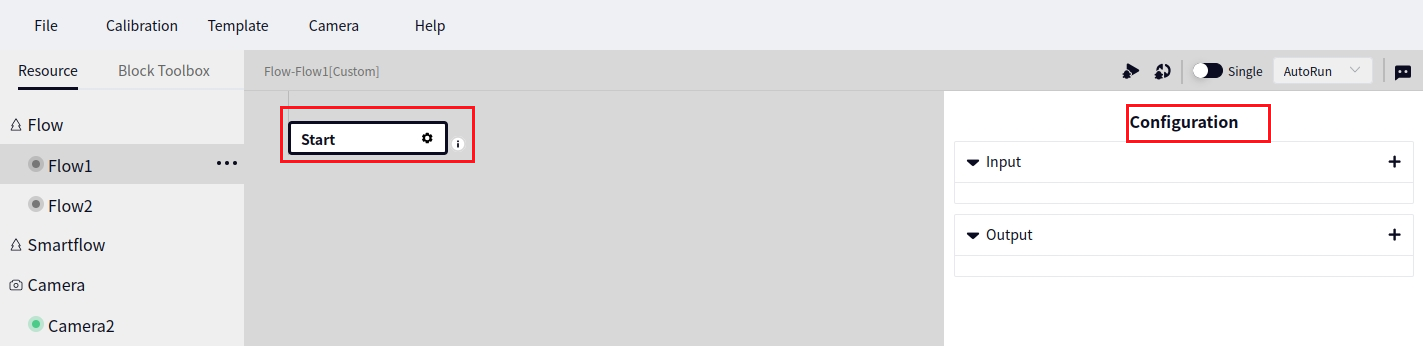
Click “Start Configuration”; a parameter configuration interface will pop up, as shown below:
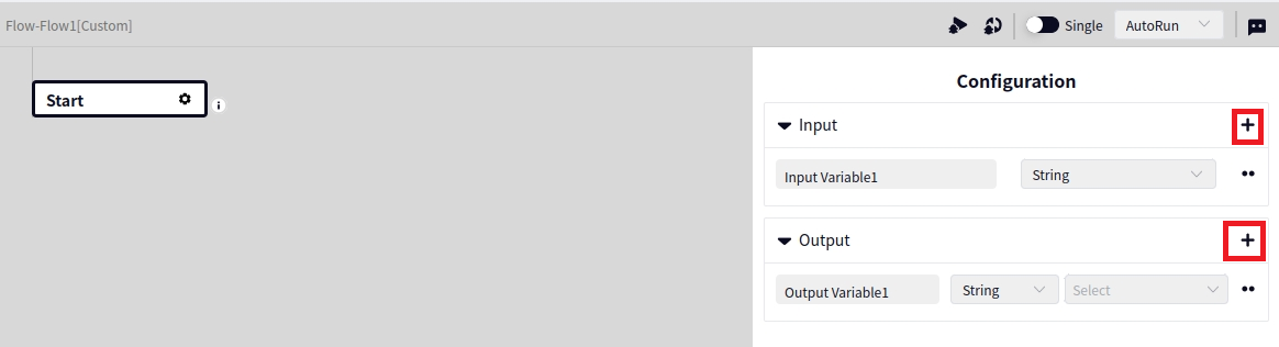
In the parameter configuration interface, you can configure the input and output of the process. Click the + sign behind Input or Output to add input or output variables. The figure below shows adding an input and an output, respectively:
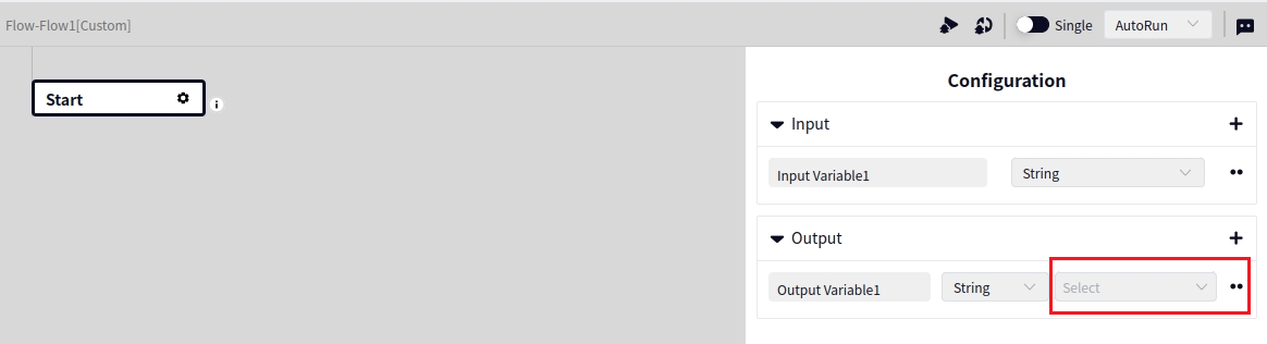
The default type of new variables is String, which can be changed via the dropdown box. For output variables, select the corresponding variable from the dropdown box as shown below:
Tip
The configured input and output variables correspond to the input and output variables in the vision plugin, which will be introduced later in the plugin section.
Operator Configuration#
Find Operator#
Click on a process with the mouse, and then click the operator toolbox to display the operator toolbox interface:
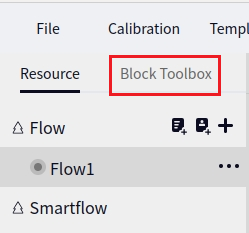
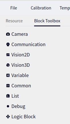
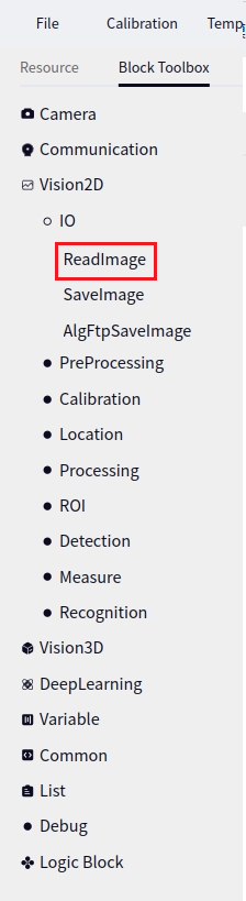
Clicking on the primary directory that contains the operators in the operator toolbox will expand it. For example, to find the image reading operator, click 2D Vision -> Input and Output:
Add Operator to Process#
Add Operator to the End#
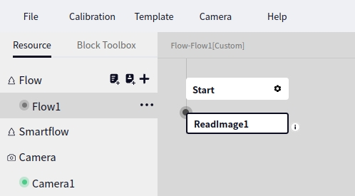
Single click Start Configuration with the mouse, then double click the operator name you wish to add to add it to the end of the process. The figure below shows the result of double-clicking the Image Reading operator:
Drag Operator to Specific Position#
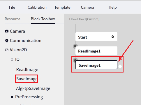
Hold down the left mouse button to drag the operator to the desired position in the process. If there are no operators in the process, you can only drag the operator behind Start Configuration. When the interface shows a white box as indicated by the arrow below, you can drop the operator into the specified position:
Tip
In the picture above, the Image Save operator is added behind the Image Reading operator.
Copy/Paste/Cut/Rename/Disable Operator#
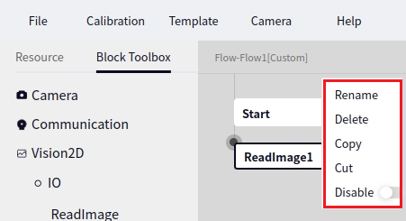
Click on an operator name with the mouse, then right-click to bring up the dialog box shown below. Click the option in the dialog box to perform the corresponding operation on the operator:
After Copying/Cutting an operator, move the mouse to the desired location and right-click when Paste Here appears, as shown below:
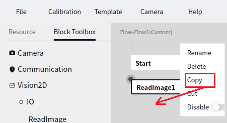
The figure above shows copying the Image Reading operator and then moving the mouse behind the Image Save operator. When the blank area appears, right-click to bring up Paste Here and click to paste.
Tip
Copying and pasting operators can be done between different processes within the same project, but cutting and pasting operators can only be done within the current process.
Disabling an operator will prevent it from being run when the entire process is run, and the operator’s parameters cannot be configured.
Process and Templates#
Add Process from Preset Template#
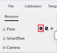
Click the first symbol behind Resource->Process to add a process from a preset template, as shown below:
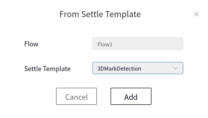
A dialog box will appear after clicking. Select 3D marker block positioning in the Preset Template dropdown box and click add. The Process Name can be default or customized:
Tip
Adding from preset template currently only supports 3D marker block positioning templates.
Add Process from Template File#
Click the second symbol behind Resource->Process to add a process from a local template file, as shown below:
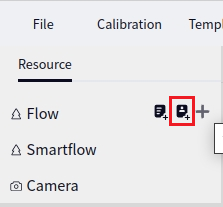
Tip
Adding from a template file can only choose files of type xxx.dmjspf. Detailed instructions on how to generate this file type will be provided in the templates section.
Export Process Template#
Select the process you need to export with the mouse, then click the First Icon, as shown below:
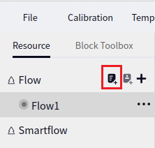
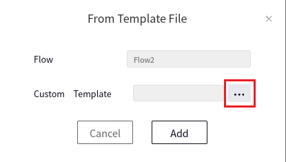
In the pop-up Export Template window, click the icon as shown below to choose the directory and name to save. You can also directly enter a name to save in the current directory by default:
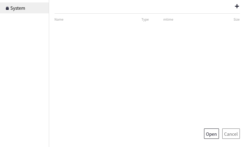
Double-click the existing folder name in the pop-up window to change the save path for the template. Click the + sign in the upper right corner to create a new folder. The first new folder is named new folder1 by default:
Finally, click export.
Tip
Exporting process templates will automatically add the suffix dmjfps to the template name.
Camera Management#
Create a New Camera#
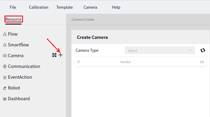
Click on Resources and then move the mouse over Camera. A + sign will appear next to Camera. Click the + sign to open the interface for creating a new camera, as shown below:
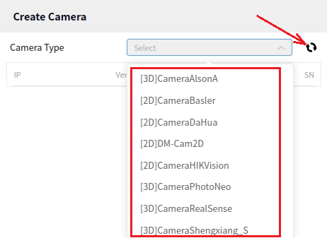
In the dropdown menu for selecting the camera model, you can choose the model you need. After selecting the model, click the Scan button next to the model to check if the device with the current model is present.
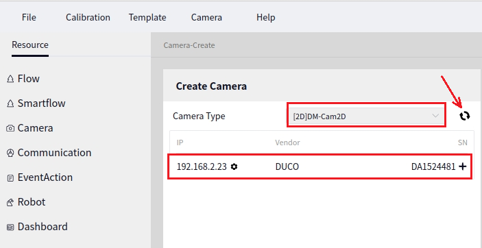
The figure below shows the result after selecting the camera model DM Camera 2D and clicking Scan.
Tip
The result above shows that a Zhiwei Camera has already been connected to the local device, and you need to wait a few seconds after clicking scan to see the results.
After the desired camera is found, click the + sign next to the scanned camera information to create a new camera, as shown below:
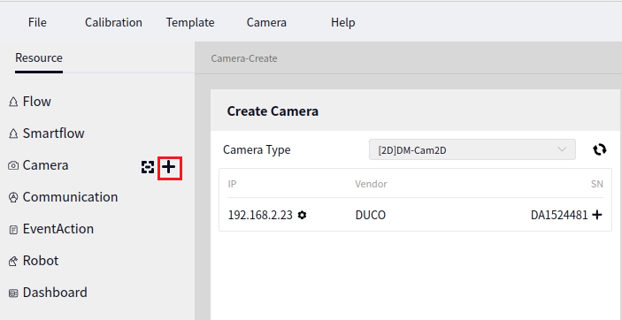
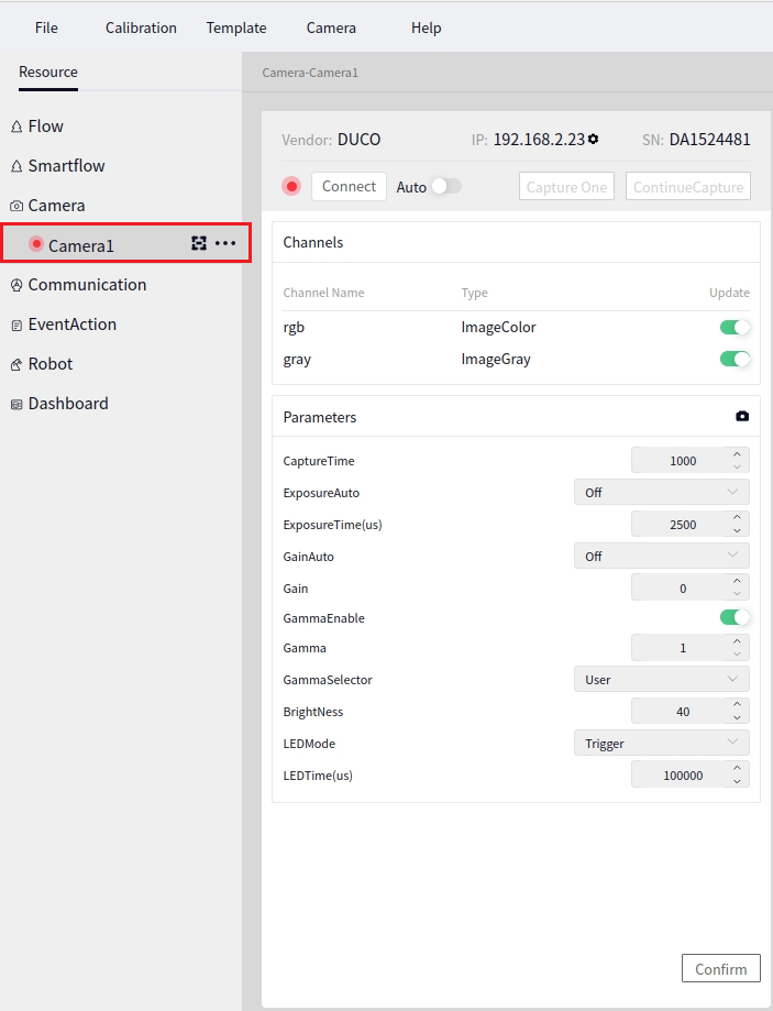
After creating a new camera, the name of the first newly created camera defaults to Camera1. Click on Camera1 to bring up the camera configuration interface, as shown below:
Renaming the Camera#
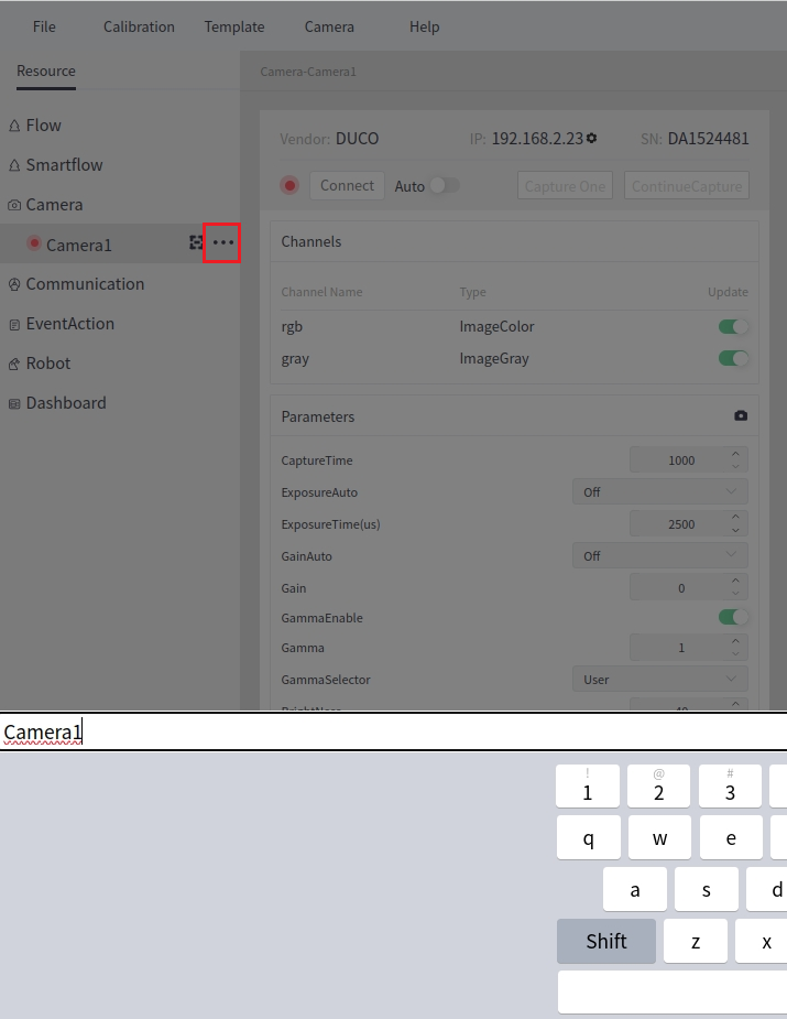
Click the first button after the camera name to bring up a dialog box for editing the camera name. The following image shows the effect after clicking the rename button next to Camera1.
Deleting the Camera#
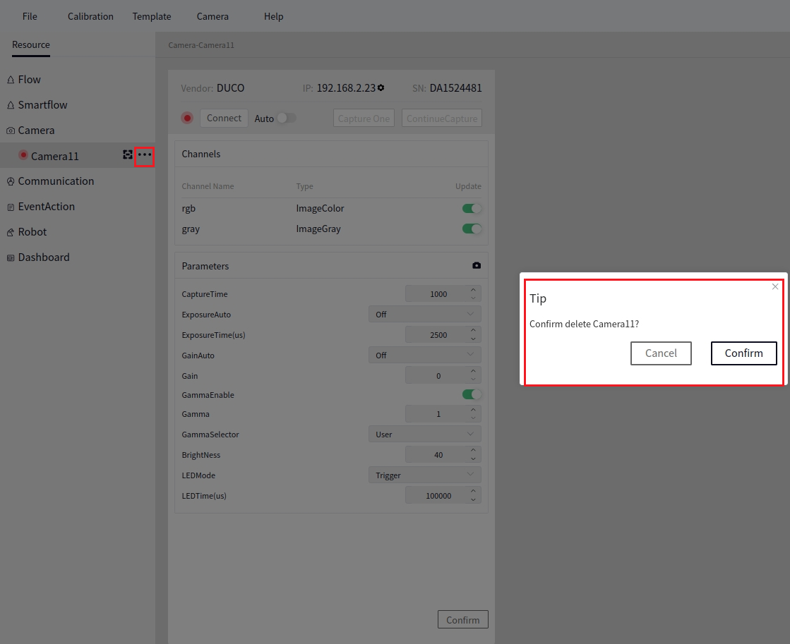
Click the second button after the camera name to bring up a confirmation box to delete the camera. Click Confirm to delete, as shown below:
Camera Shooting#
All Cameras Capture#
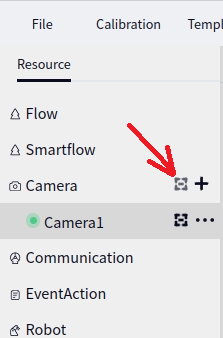
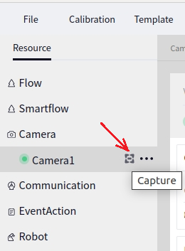
As shown in the figure below, moving the mouse to the back of the camera will display the capture icon as shown in the figure below. Clicking the icon at this time will take photos with all cameras connected to the software.
Single Camera Capture#
As shown in the figure below, moving the mouse to the back of a specific camera will display the capture icon as shown in the figure below. Clicking the icon at this time will take a photo with that specific camera.
Camera Configuration#
Zhisensor Camera#
Create#
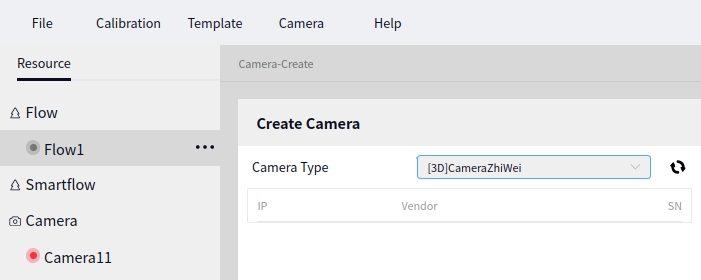
Choose the camera model as Zhisensor when creating a new camera, as shown below:
Tip
For detailed steps on how to create a new camera, refer to Create Camera section.
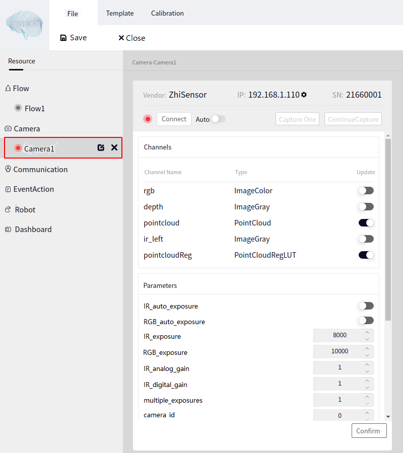
After creating the Zhisensor camera, click on the camera name to bring up the configuration interface of the Zhisensor camera, as shown below:
Connect and Disconnect#
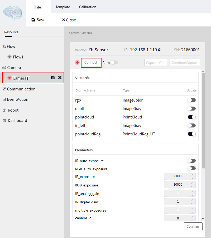
Click the Connect button, and the system will attempt to connect to the Zhisensor Camera. It usually takes a few seconds to connect successfully. Once connected, the Connect button will change to Disconnect, as shown below:
Tip
Zhisensor Camera generally uses a POE interface. After connecting to the device, configure the connected network port to Local-Link Only to connect successfully (if you know the camera’s IP in advance, you can set the network to the same segment as the camera).
If the camera fails to connect, an error window will pop up. In this case, you need to check the network port configuration and verify that the network cable and camera are intact.
Parameter Configuration#
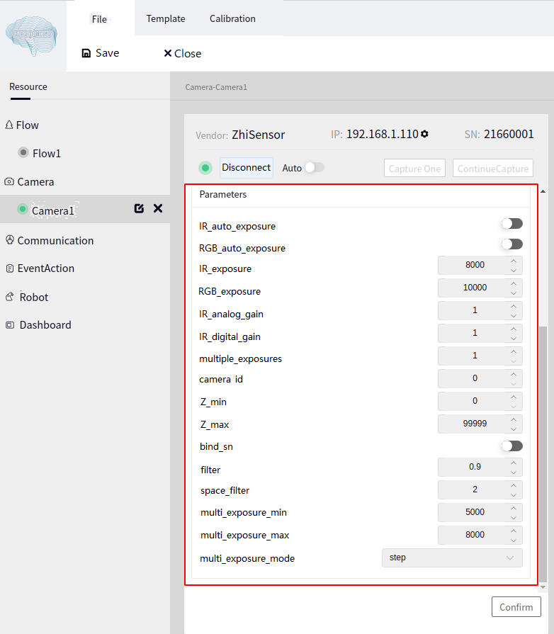
The parameter configuration interface for the Zhisensor Camera is shown below:
Tip
The parameters we frequently configure include IR Exposure and Multiple Exposure Count.
IR Exposure: Adjust this parameter if the camera captures images that are too bright or too dark.
Multiple Exposure Count: Number of exposure times of the camera.
Click the confirm button to take effect after setting.
Output Channel Configuration#
The various output channels of the Zhisensor Camera are shown below:
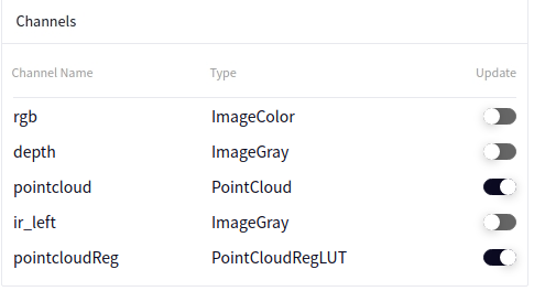
Click the toggle button after data update. Moving the dot to the right indicates enabling, and to the left indicates disabling. After switching a channel, click the Confirm button to take effect.
Tip
rgb indicates a color image, currently available only in D130, D130S, and D132 series.
depth indicates a depth map.
pointcloud indicates a point cloud.
ir_left indicates the left infrared.
pointcloudReg is a data format for storing row and column information of point clouds. This data type is used with operations like Point Cloud Area Segmentation or 3D calibration panel. This data type cannot be viewed in global variables once enabled.
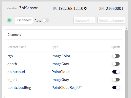
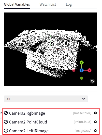
The following image shows the result after enabling all data channels of the Zhisensor Camera (Camera1). Once enabled, you can see all output types of the camera in the global variable table on the right side:
Photography#
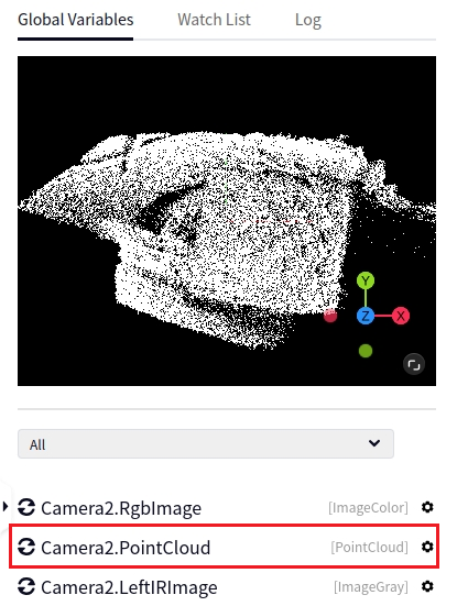
Click the Single Capture button on the camera interface to take one photo. After capturing, you can view the corresponding output data in the Global Variable Table. The following image shows the point cloud data of Camera1:
Continuous Shooting#
Click the Continuous Capture button on the camera interface to take consecutive photos.
Dahua Camera#
Create#
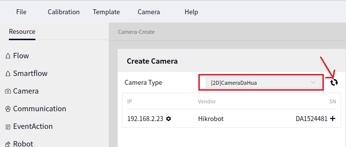
Select Dahua Camera from the camera model options when creating a new camera, as shown in the image below:
Tip
For details on how to create a new camera, refer to the New Camera section
After creating the Dahua Camera, click on the camera name to bring up the Dahua Camera configuration interface
Connect and Disconnect#
Click the Connect button to attempt to connect to the Dahua Camera. It usually takes a few seconds to connect successfully. Once connected, the Connect button will change to Disconnect
Parameter Configuration#
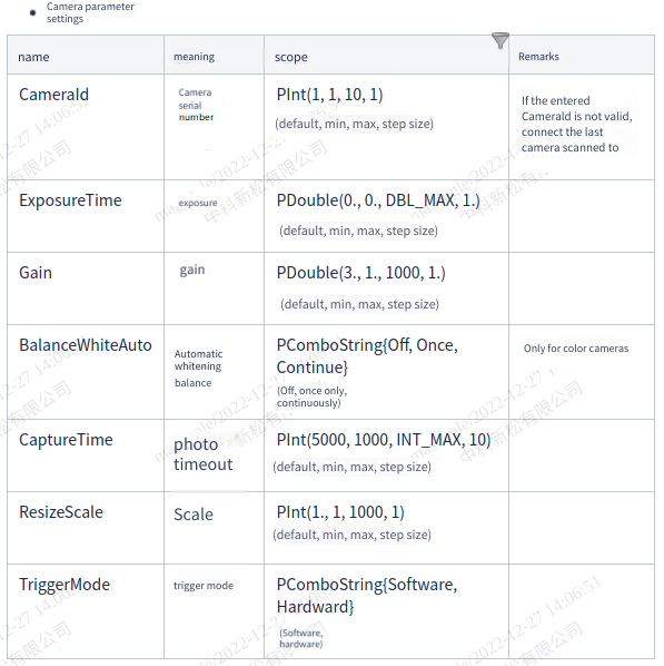
The image below shows the parameter configuration interface for the Dahua Camera
Output Channel Configuration#
Dahua Camera is a 2D camera, and the output data will either be rgb or gray
Taking Photos#
Click the Single Capture button in the camera interface to take a single photo. After capturing, the output data can be viewed in the Global Variables Table
Continuous Capture#
Click the Continuous Capture button in the camera interface for continuous shooting
RealSense Camera#
Create#
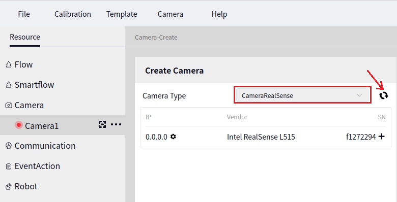
Select the camera model as RealSense Camera when creating a new camera, as shown below:
Tip
For detailed steps on how to create a camera, refer to the New Camera section.
Click the camera name after creating the RealSense Camera to open the configuration interface for the RealSense Camera.
Connect and Disconnect#
After clicking the Connect button, the system will attempt to connect to the RealSense Camera. It generally takes a few seconds to connect successfully. Once connected, the Connect button will turn into the Disconnect button.
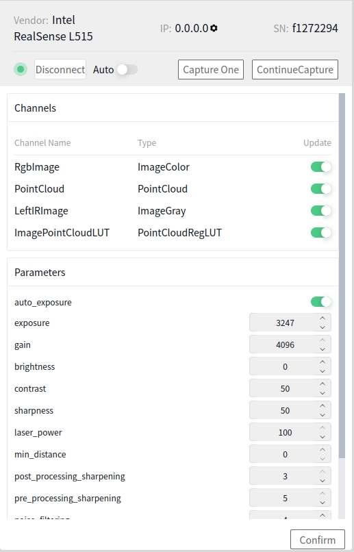
Parameter Configuration#
The following image shows the parameter configuration interface for the RealSense camera.
Output Channel Configuration#
The following image shows the various output channels of the RealSense Camera.
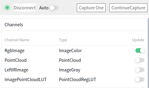
Click the toggle button for data updates. Moving the dot to the right indicates it is on, and moving it to the left indicates it is off. After toggling a channel, you need to click the Confirm button for it to take effect.
Tip
rgb represents the color image.
pointcloud represents the point cloud.
ir_left represents the left infrared.
pointcloudReg is a data format for storing point cloud row and column information. This data type is used with the Point Cloud Region Segmentation operator or a 3D calibration board. Once this data type is enabled, it cannot be viewed in the global variable table.
Take Photo#
Click Single Photo on the camera interface to take a single photo. After the photo is taken, you can view the corresponding output data in the Global Variable Table.
Continuous Photo#
Click Continuous Photo on the camera interface to take continuous photos.
Basler Camera#
Create#
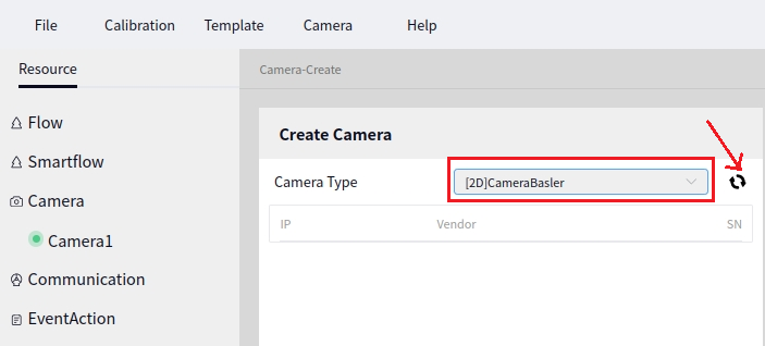
When creating a new camera, select the camera model as Basler Camera, as shown below:
Tip
For specific instructions on how to create a new camera, refer to the New Camera section.
After creating the Basler Camera, click on the camera name to open the Basler Camera configuration interface.
Connect and Disconnect#
Click the Connect button to allow the system to attempt to connect to the Basler Camera. It usually takes a few seconds to connect successfully. Once connected, the Connect button will change to a Disconnect button.
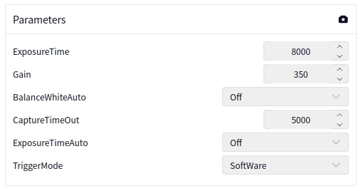
Parameter Configuration#
The following image shows the parameter configuration interface for the Basler Camera:
Caution
The auto white balance parameter can only be used on color Basler cameras.
Output Channel Configuration#
The Basler Camera is a 2D camera, and the output data can either be rgb or gray. When the camera is successfully connected, it will detect whether the current camera is a grayscale camera or a color camera.
Taking Photos#
Click the Single Photo button on the camera interface to take a single photo. After taking the photo, you can view the corresponding output data in the Global Variable Table.
Continuous Photo#
Click the Continuous Photo button on the camera interface to take photos continuously.
Hikvision Camera#
Create#
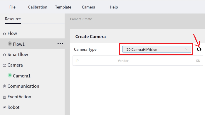
When creating a new camera, select the camera model as Hikvision Camera as shown in the following image:
Tip
For detailed steps on how to create a new camera, refer to the instructions in Create New Camera
Once the Hikvision Camera is created, click on the camera name to bring up the Hikvision Camera configuration interface.
Connect and Disconnect#
Click the Connect button, and the system will attempt to connect to the Hikvision Camera. It usually takes a few seconds to connect successfully. Once connected, the Connect button will change to the Disconnect button.
Parameter Configuration#
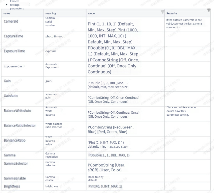
The following image shows the parameter configuration interface for the Hikvision Camera:
Output Channel Configuration#
The Hikvision Camera is a 2D camera, and the output data will either be rgb or gray.
Take Photo#
Click the Single Capture button on the camera interface to take a single photo. After the photo is taken, you can view the corresponding output data in the Global Variable Table.
Continuous Capture#
Click the Continuous Capture button on the camera interface for continuous shooting.
PhotoNeo Camera#
Create#
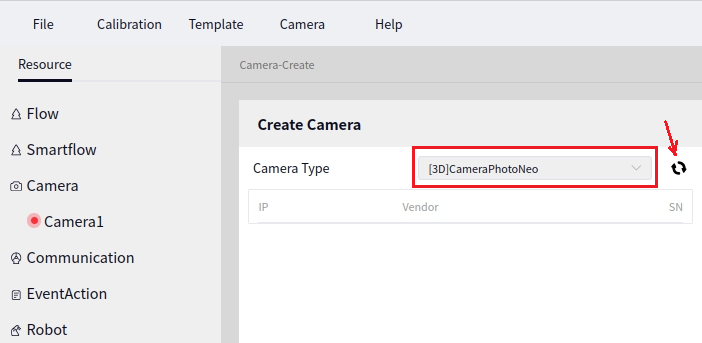
When creating a new camera, simply select the PhotoNeo Camera model, as shown below:
Tip
For details on how to create a new camera, refer to the Create New Camera section.
After creating a PhotoNeo Camera, click on the camera name to bring up the configuration interface for the PhotoNeo Camera.
Connect and Disconnect#
Click the Connect button, and the system will attempt to connect to the PhotoNeo Camera. It usually takes a few seconds to connect successfully. Once connected, the Connect button will change to a Disconnect button.
Parameter Configuration#
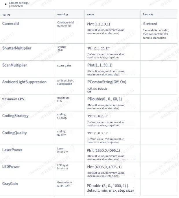
The following image shows the parameter configuration interface for the PhotoNeo Camera:
Output Channel Configuration#
The following image shows the various output channels of the PhotoNeo Camera:
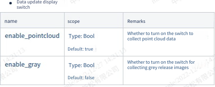
Click the toggle button to update the data. Moving the dot to the right end signifies enabled, while moving it to the left signifies disabled. After toggling a channel, you need to click the Confirm button for the changes to take effect.
Tip
pointcloud means point cloud.
gray means grayscale image.
pointcloudReg is a data format for storing point cloud row and column information, used in conjunction with the Point Cloud Segmentation operator or 3D calibration board. Once this data type is enabled, its content cannot be viewed in global variables.
Photography#
Clicking Single Photo on the camera interface takes a single photo. After the photo is taken, the corresponding output data can be viewed in the Global Variables Table.
Continuous Photography#
Clicking Continuous Photo on the camera interface enables continuous photography.
Megaphase Camera#
Create#
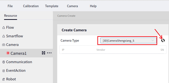
Select the camera model as Megaphase Camera when creating a new camera, as shown in the image below:
Tip
For detailed instructions on how to create a new camera, refer to the New Camera section.
After creating the Megaphase Camera, click on the camera name to open the configuration interface for the Megaphase Camera.
Connect and Disconnect#
Click the Connect button, and the system will attempt to connect to the Megaphase Camera. It usually takes a few seconds to connect successfully. Once connected, the Connect button will turn into a Disconnect button.
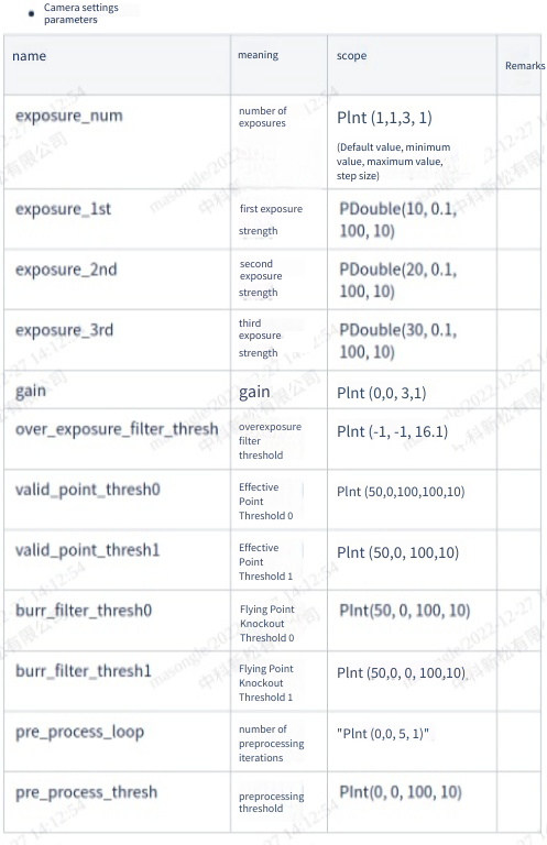
Parameter Configuration#
The parameter configuration interface for the Megaphase camera is shown below:
Output Channel Configuration#
The output channels for the Megaphase Camera are shown in the image below:
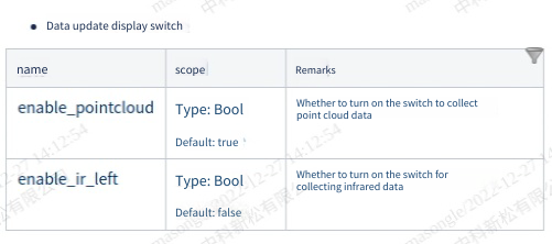
Click the toggle button after data updates. Move the dot to the right to enable, and to the left to disable. After toggling a channel, you need to click the Confirm button for the changes to take effect.
Tip
pointcloud represents the point cloud.
ir_left represents the left infrared.
pointcloudReg is the data format that stores point cloud row and column information. This data type is used in conjunction with the Point Cloud Region Segmentation operator or 3D calibration board. Once this data type is enabled, its content cannot be viewed in the global variable table.
Take a Photo#
Click Single Capture on the camera interface to take a single photo. After the photo is taken, the corresponding output data can be viewed in the Global Variable Table.
Continuous Shooting#
Click Continuous Capture on the camera interface to take photos continuously.
Percipio Camera#
Create#
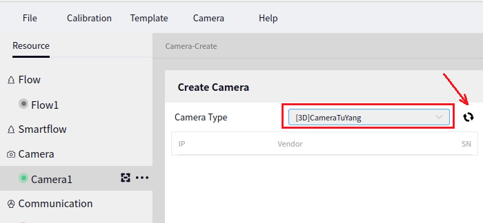
When creating a new camera, select the camera model as Percipio Camera, as shown below:
Tip
For more details on how to create a new camera, refer to the Create Camera section.
After creating the Percipio Camera, click on the camera name to bring up the configuration interface for the Percipio Camera.
Connect and Disconnect#
Clicking the Connect button will prompt the system to try to connect to the Percipio Camera. Generally, it takes a few seconds to connect successfully. Once connected, the Connect button will change to Disconnect.
Parameter Configuration#
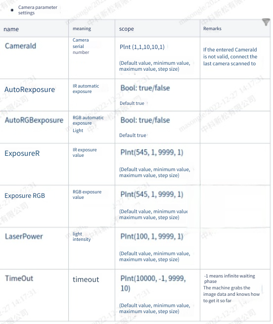
The figure below shows the parameter configuration interface of the Percipio Camera.
Output Channel Configuration#
The figure below shows the various output channels of the Percipio Camera.
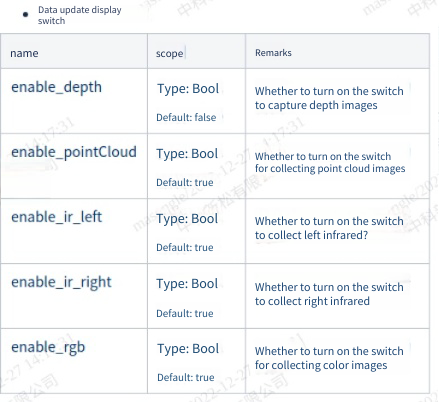
Click the toggle button to update data. Moving the dot to the right end means enabling the channel, and moving it to the left end means disabling it. After toggling a channel, you need to click the Confirm button to take effect.
Tip
rgb indicates color images. Currently, only the D130, D130S, and D132 series have color images.
depth represents depth maps.
pointcloud represents point clouds.
ir_left represents the left infrared.
ir_right represents the right infrared.
pointcloudReg is the data format for storing point cloud row and column information. This data type is used in conjunction with the Point Cloud Region Segmentation operator or 3D calibration board, and this data type cannot be viewed in global variables once enabled.
Take a Photo#
Clicking Single Photo on the camera interface takes a single photo. After taking the photo, you can view the corresponding output data in the Global Variable Table.
Continuous Shooting#
Clicking Continuous Photo on the camera interface allows for continuous shooting.
Alsontech Camera A Series#
Create#
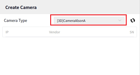
When creating a new camera, select the camera model as Alsontech Camera A, as shown below:
Tip
For details on how to create a new camera, refer to the Create New Camera section.
After creating the Alsontech Camera A, click on the camera name to bring up the configuration interface for Alsontech Camera A.
Connect and Disconnect#
Click the Connect button, and the system will attempt to connect to the Alsontech Camera A. It usually takes a few seconds to successfully connect. Once connected, the Connect button will change to the Disconnect button.
Parameter Configuration#
The following is the parameter configuration interface for Alsontech Camera A:
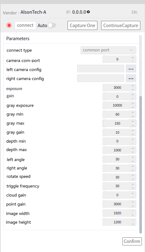
Tip
When connecting an Alsontech A series camera, you can choose either a standard serial port or a USB serial port. After selecting the port, click “OK” and then click “Connect” to establish the connection.
Output Channel Configuration#
The following are the various output channels of the Alsontech Camera A:
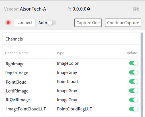
Click the toggle button after data is updated. Moving the dot to the right end means the channel is enabled, and moving it to the left end means it is disabled. After toggling a channel, you need to click the Confirm button to apply the changes.
Tip
pointcloudReg is the data format for storing point cloud row and column information. This data type is used with the Point Cloud Region Segmentation operator or 3D calibration board. After enabling this data type, content cannot be viewed in global variables.
Take Photo#
Click the Single Capture button on the camera interface to take a single photo. After the photo is taken, you can view the corresponding output data in the Global Variable Table.
Continuous Capture#
Click the Continuous Capture button on the camera interface for continuous shooting.
Vizumtech Camera#
Create#
When creating a new camera, select the camera model as Vizumtech Camera and click scan, as shown below:
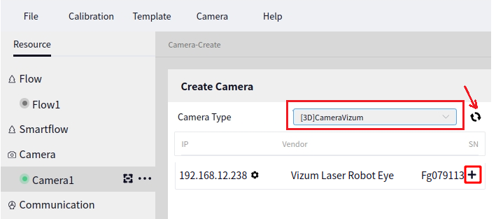
After clicking scan, click the + next to the camera in the above image to add the camera.
Tip
For specific steps on how to create a new camera, refer to the Create New Camera section.
After creating the Vizumtech Camera, click on the camera name to open the Vizumtech Camera configuration interface, as shown below:
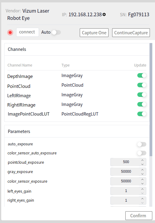
Caution
Vizumtech Camera is a network camera. You need to know the camera’s IP address information before connecting. Specific camera information can be confirmed with the manufacturer.
The network segment of the Ethernet port between the controller and the camera needs to be consistent with the camera settings before connecting.
Connect and Disconnect#
After clicking the Connect button, the system will try to connect to the Vizumtech Camera. Generally, it takes a few seconds to connect successfully. Once connected, the Connect button will become the Disconnect button.
Parameter Configuration#
As shown below, this is the 2D parameter configuration interface for the E Series Elson Camera.
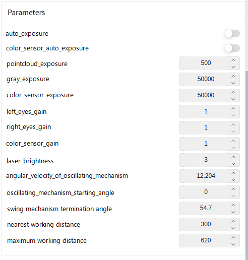
Commonly used parameters for this camera’s point cloud and left/right infrared images are:
Point Cloud Exposure: The exposure value of the camera when obtaining point clouds. This value should typically not be too high; a value of 500 usually provides good point cloud effects. Setting this value too high or too low may result in abnormal point clouds.
Gray Exposure: The exposure value when obtaining left and right infrared grayscale images. The larger the value, the brighter the grayscale image. This value should be set according to the environment.
Left/Right Eyes Gain: The gain value when obtaining left and right infrared grayscale images.
Angular Velocity Of Oscillating Mechanism: The scanning speed of the laser when scanning point clouds.
Oscillating Mechanism Starting Angle: The starting angle of the laser when scanning point clouds.
Swing Mechanism Termination Angle: The stopping angle of the laser when scanning point clouds.
Nearest Working Distance: The nearest photo distance of the camera. This must be set and should be less than the distance between the camera and the object to be photographed.
Maximum Working Distance: The farthest photo distance of the camera. This must be set and should be greater than the distance between the camera and the object to be photographed.
Caution
Any parameter changes will only take effect after clicking the Confirm button.
Output Channel Configuration#
The output channels of the Vizumtech Camera are shown below:
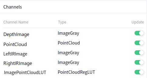
Depth Image: Grayscale 2D image.
Left IR Image: 2D grayscale image taken by the left eye of the camera. This image corresponds one-to-one with the point cloud data.
Right IR Image: 2D grayscale image taken by the right eye of the camera. This image corresponds one-to-one with the point cloud data.
Image Point Cloud LUT: Data format storing point cloud row and column information, used for looking up 3D point cloud information in 2D images.
Point Cloud: 3D point cloud information captured by the camera.
After clicking the update switch button, moving the dot to the right end means enabled, to the left end means disabled. After switching any channel, click the Confirm button for the changes to take effect. Disabling a channel will stop outputting the data information of that channel.
Tip
The Image Point Cloud Lookup Table is a data format that stores point cloud row and column information. This data type is used in conjunction with the Point Cloud Region Segmentation operator or 3D calibration board. After enabling this data type, its contents cannot be viewed in global variables.
Capture Photo#
Clicking Single Capture in the camera interface means taking a single photo. After capturing, the corresponding output data can be viewed in the Global Variable Table.
Continuous Capture#
Clicking Continuous Capture in the camera interface means continuous photo capture.
DM-Cam2D Camera#
Create#
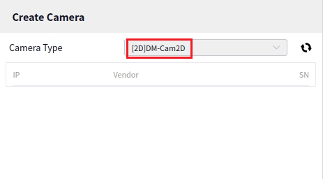
When creating a new camera, choose the camera model [2D]DM-Cam2D as shown below:
Tip
For details on how to create a new camera, refer to the content in Creating a New Camera.
After creating the [2D]DM-Cam2D, click the camera name to open the configuration interface of the [2D]DM-Cam2D.
Connect and Disconnect#
Click the Connect button, and the system will attempt to connect to the [2D]DM-Cam2D. Typically, it takes a few seconds to connect successfully. Once connected, the Connect button will change to the Disconnect button.
Parameter Configuration#
Below are the common configuration parameters for DM-Cam2D:
Photograph Timeout: Indicates the maximum time the camera will wait to capture an image. If no image is captured within this time frame, an error will be reported. The default value is usually sufficient.
Exposure: The exposure time of the camera. This parameter is adjusted only when Auto Exposure is turned off. The exposure value should be adjusted according to the actual situation.
Auto Exposure: - Off: Usually, Auto Exposure will be set to Off, and then the Exposure time is manually adjusted. - One Time - Continuous
Gain: The gain value of the camera. This parameter is adjusted only when Auto Gain is turned off. The gain value should be adjusted according to the actual situation.
Auto Gain: - Off: Usually, Auto Gain will be set to Off, and then the Gain value is manually adjusted. - One Time - Continuous
Light Source Mode: - Constant Light: Indicates that the camera’s light source will be continuously on. - Triggered: Indicates that the light source will turn on once each time a photograph is taken and will be off when not taking a photograph.
Light Source Delay: Indicates the duration of the light source when it follows the working time of the camera.
Tip
Regardless of which parameter is set, after setting the parameters, be sure to click the OK button to apply the settings.
Output Channel Configuration#
DM-Cam2D is a 2D camera, and the output data will either be gray, meaning this camera only provides grayscale images.
Taking Photos#
Click the Single Photo button on the camera interface to take a single photo. The corresponding output data can be viewed in the Global Variable Table once the photo is taken.
Continuous Shooting#
Click the Continuous Shooting button on the camera interface to take photos continuously.
Communication Management#
Create New Communication#
Click the + sign next to Communication under the Resources menu to open the Create New Communication interface, as shown below:
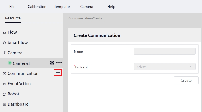
In the Communication Protocol dropdown box, you can select either TCP Client or TCP Server. After selecting the communication protocol, a communication name will be automatically generated, but you can also name it yourself. The following image shows the result after selecting TCP Client:
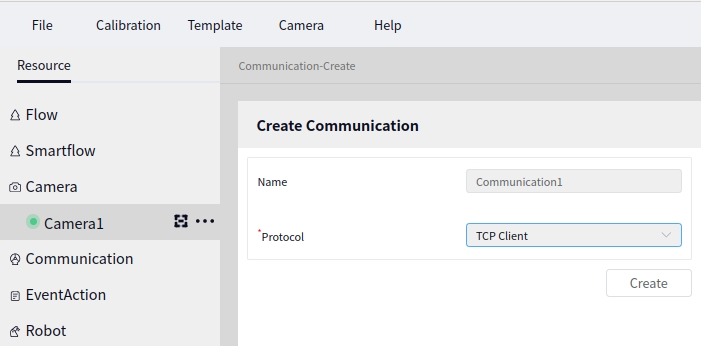
In the above image, click Create to create a new TCP Client named Communication1. Click on Communication1 to view the communication configuration interface (as shown below). The process for creating a new TCP Server is the same as for the client.
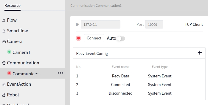
Communication Configuration#
Rename Communication#
Click on the communication you want to rename, and then click the first icon after the communication name, as shown below:
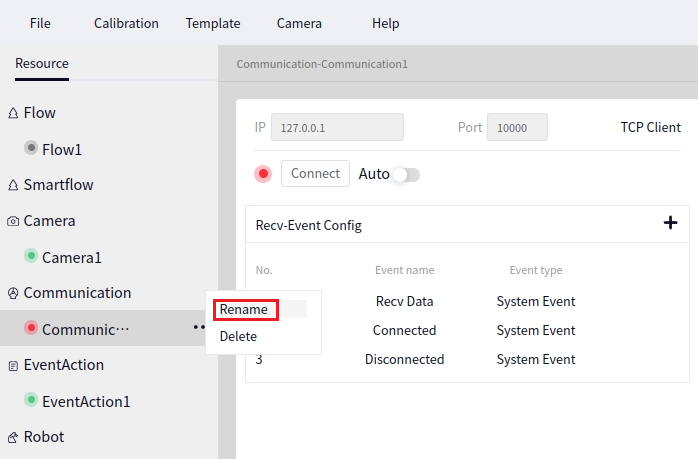
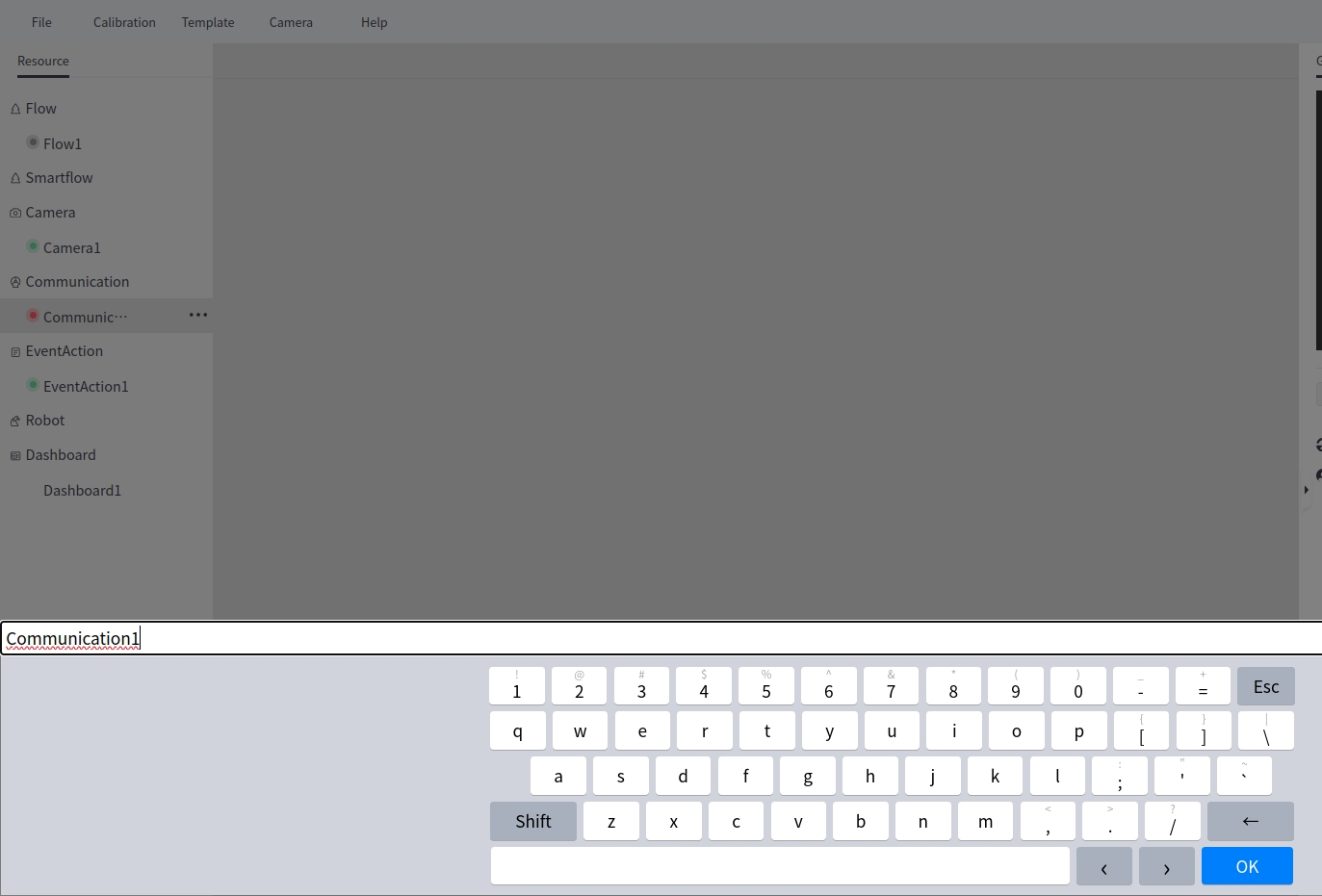
Enter the new name in the input box in the above image and click Confirm.
Delete Communication#
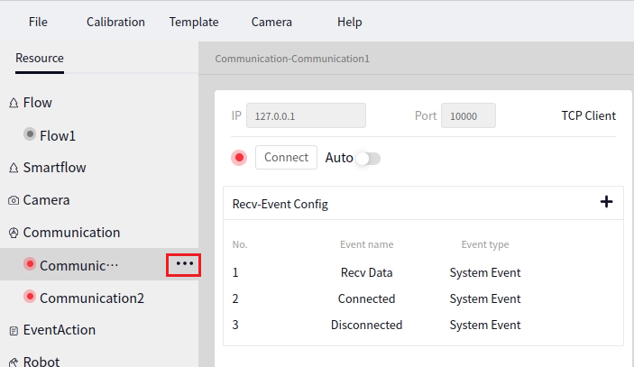
Click on the communication you want to delete, and then click the second icon after the communication name, as shown below:
Tip
Deleted communications cannot be recovered.
Communication Event Configuration#
Click on the existing communication name, such as Communication1 in the image below, and then click Event Configuration-Receive Data followed by the + sign, as shown below:
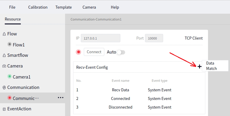
Clicking the + sign will bring up the Data Matching prompt. Click Data Matching to add a new data matching event, as shown below:
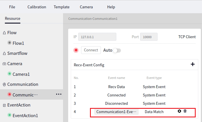
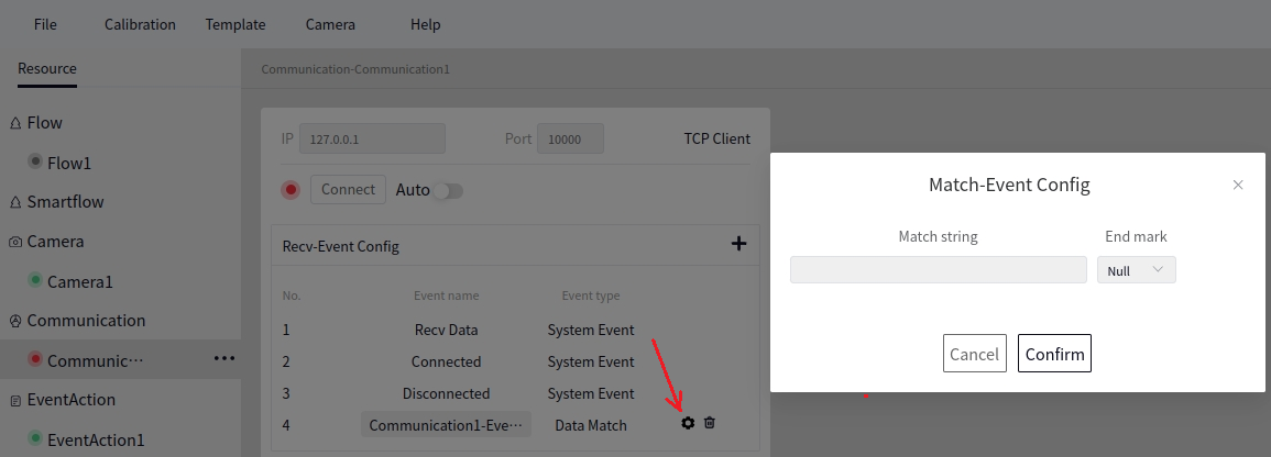
Clicking Communication1-Event1 in the above image allows you to change the name. Click the settings button next to Communication1-Event1 to configure the matching characters and terminators, as shown below:
Tip
The configuration methods for both TCP clients and TCP servers are the same.
Event Response Management#
Create New Event Response#
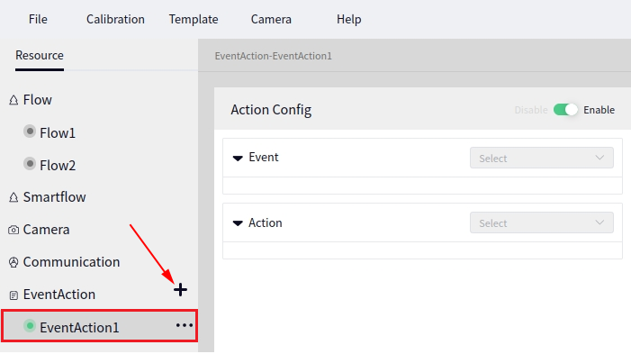
Click the + sign next to Event Response to create a new event response. As shown in the figure below, the default event name is Event Response 1.
Event Response Configuration#
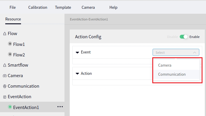
Click on the newly created event response name to pop up the Response Configuration interface. The button on the right side of the Response Configuration can be used to enable or disable the current event. Click on the Event dropdown box to configure a specific event, as shown below.
Tip
The current event only supports Camera and Communication.
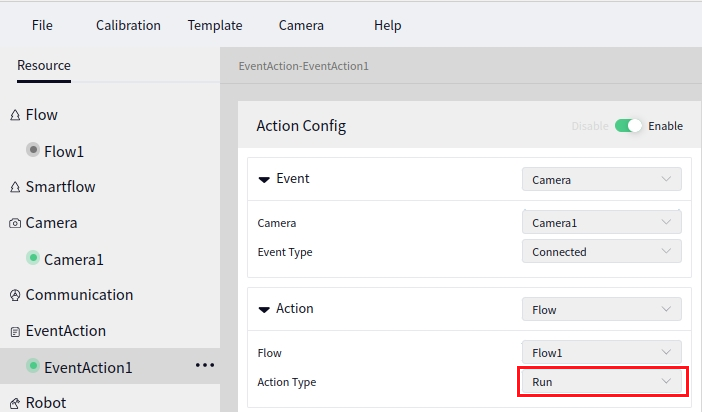
After selecting the event as Camera or Communication, you can choose a specific operation, as shown below.
Tip
Currently, you can only select a process with Operation Type as Execution Process in Operation.
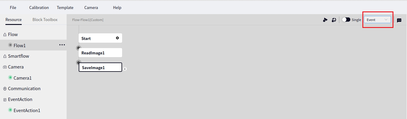
The process selected in Operation needs to be configured as Trigger Mode.
In the above figure, Process 1 is selected for execution. At this time, it is necessary to click Process 1 and set the running mode to Trigger Mode in order to receive event responses, as shown below:
Robot Management#
Create New Robot#
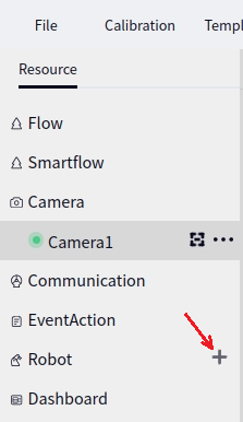
Click the + sign behind the robot to bring up the Create New Robot interface, as shown below.
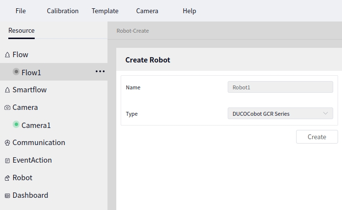
In the Create New Robot interface, you can first enter the robot’s Name and then select the Robot Model. If you select the robot model without entering a robot name, a default robot name robot1 will be generated, as shown below.
Tip
Robot model supports two types: ducocore_gcr10 and ducocore_gcr5
Click the Create button to create a new robot.
Robot Configuration#
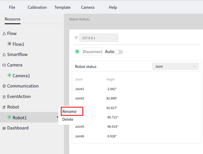
Click the name of the robot you want to configure to bring up the robot interface. Click the first icon behind the robot name to change the robot name, as shown below:
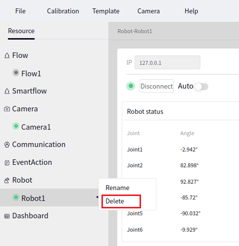
Click the second icon behind the robot name to delete the corresponding robot, as shown below:
In the robot interface, enter the IP of an existing robot and click the Connect button to connect to the robot. Once connected successfully, the Connect button will turn into Disconnect and the dot before “Connect” will turn from red to green, as shown below:
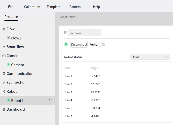
Behind the robot data, you can view the Joint Angles or TCP Pose.
Tip
The Auto button on the robot interface, when switched to the right, indicates the auto-connect is on, and when switched to the left, indicates the auto-connect is off. The auto-connect feature takes effect when the project is opened.
Data Dashboard#
Create New Data Dashboard#
Click the + sign behind the data dashboard to create a new Data Dashboard 1. The sequence number of the newly created data dashboard will automatically increment by 1, as shown below:
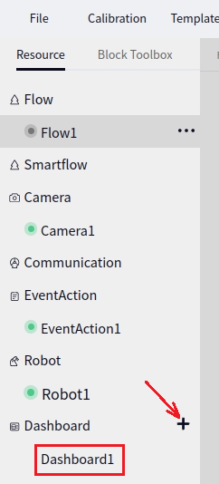
Data Dashboard Configuration#
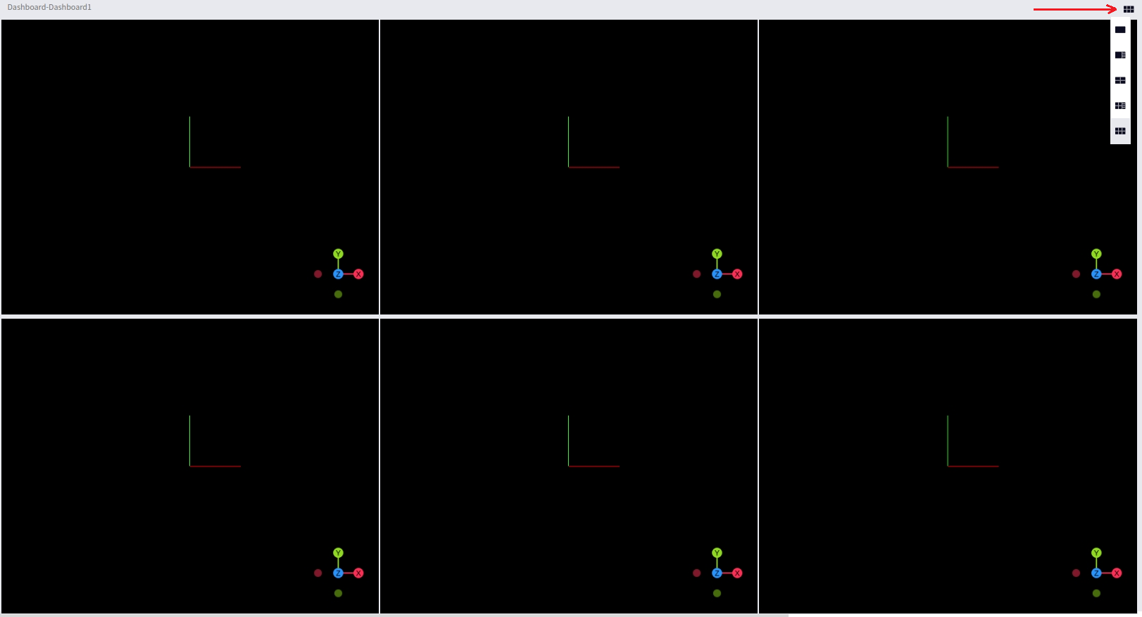
Click on the name of the newly created data dashboard to bring up the data dashboard interface. The initial layout of the data dashboard defaults to 6 data display boards, as shown below:
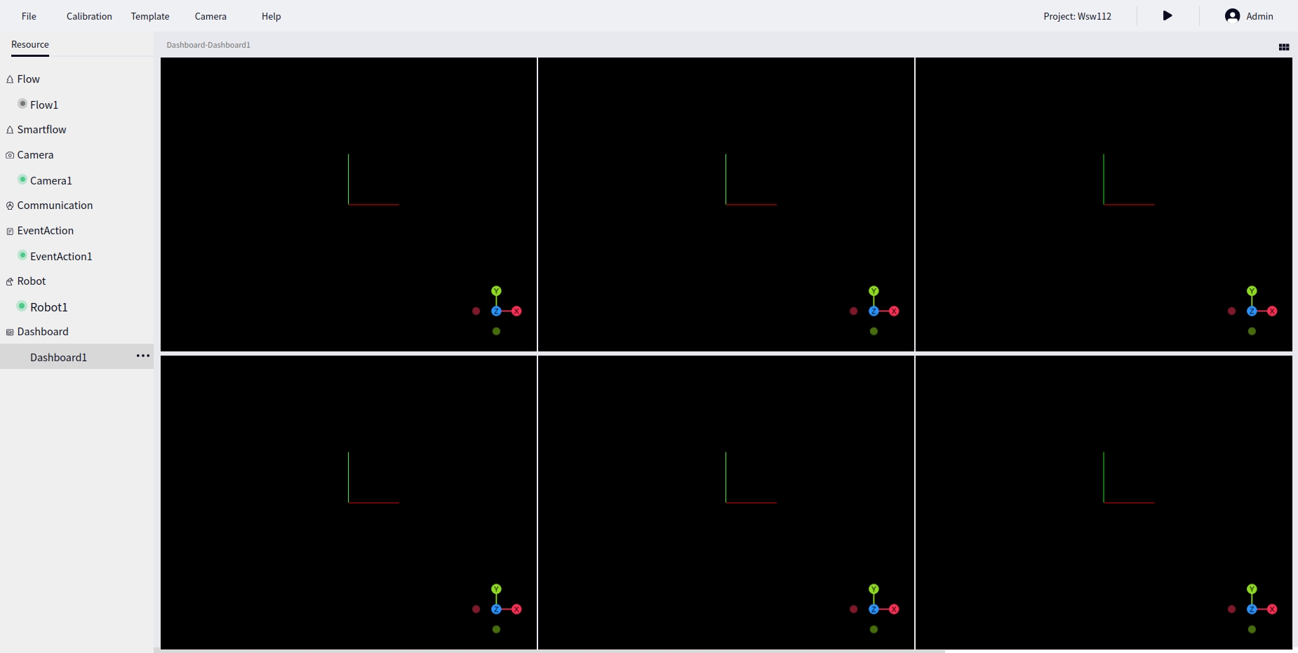
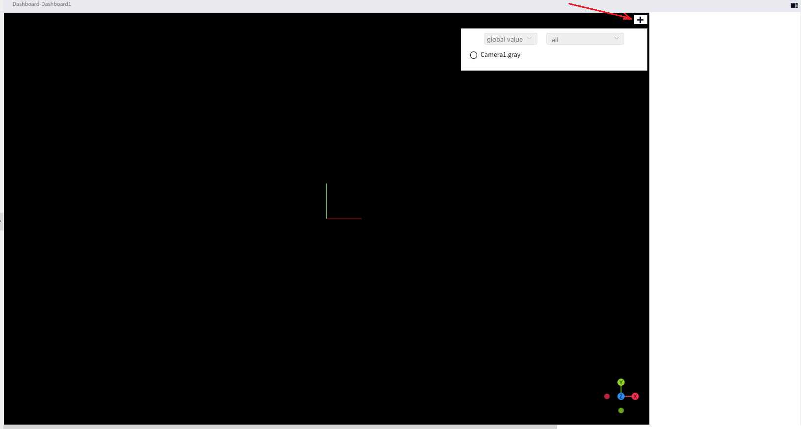
Move the mouse to the upper right corner of a certain point cloud browser to display the + sign. Click the + sign to select the data you want to display. As shown below, you can select data from Global Variables or Monitor Variables.
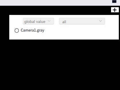
Tip
In the above image, clicking the + sign will display data that supports images, point cloud, Debug2d, and Debug3d. Clicking the + sign again will hide the data selection popup window.
Click the layout button in the upper right corner of the data dashboard to set the layout of the current data dashboard, as shown below:
When selecting the second layout or fourth layout, move the mouse to the upper right corner of the blank part on the right. At this point, a + sign will appear. Click + to display ordinary variables or arrays, as shown below:
Variable Panel#
After opening a project, you can find Global Variables and Watch Variables in the right sidebar, as shown below:
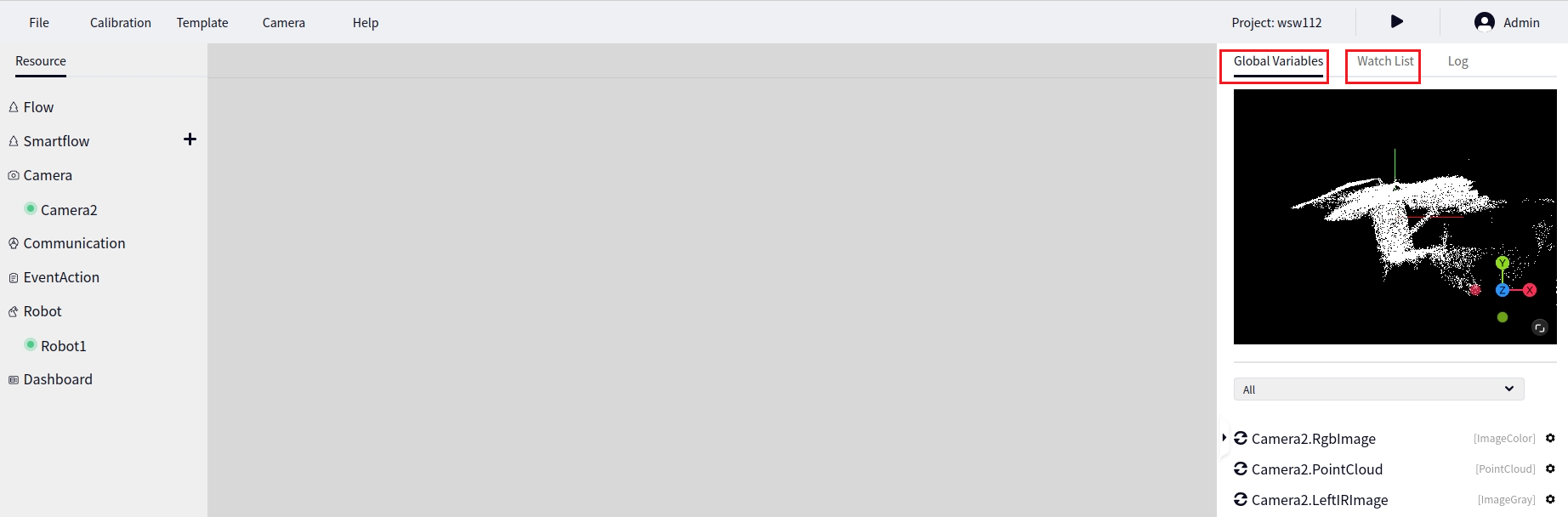
Click on the name of a Global Variable or Watch Variable to display the content of that variable.
Global Variables#
Filter#
Below the global variables, you can filter the types displayed in the current global variable list, as shown below:
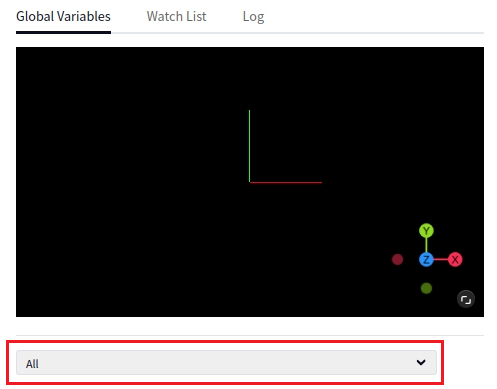
User Variables#
When global variables are filtered by a specific type, you can click the + sign to the right of the type to add a new user variable of that type. The following image shows adding a new Bool type user variable.
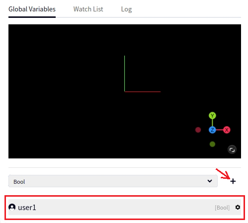
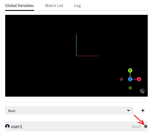
The default name for the new user variable is user1. You can click the settings button next to the user variable to Rename, Delete, and Monitor, as shown below.
Watch List#
Watch Flow Variables#
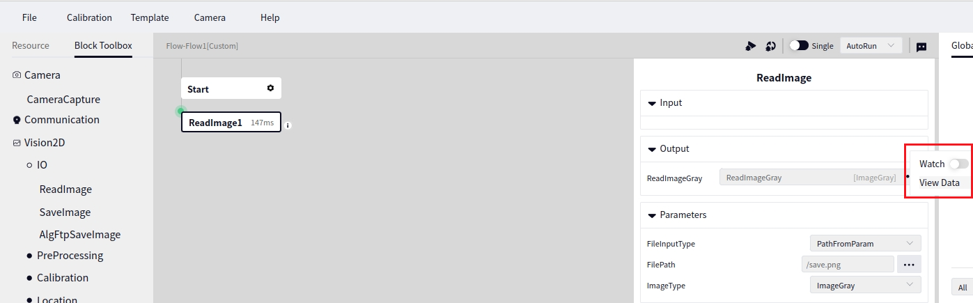
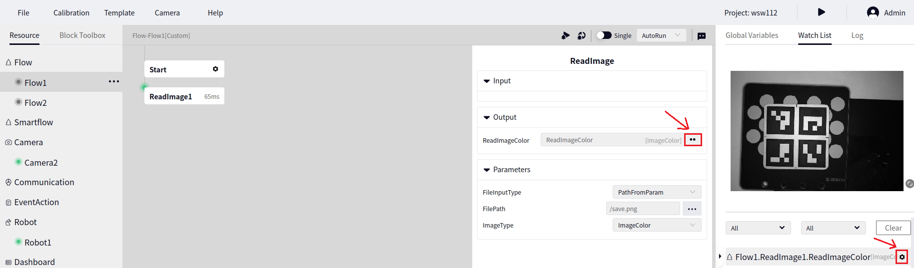
As shown below, in Process1 there is an Image Read operator. Click the Image Read operator and turn on monitoring of ReadImageColor in the output to display the variable in the Watch List.
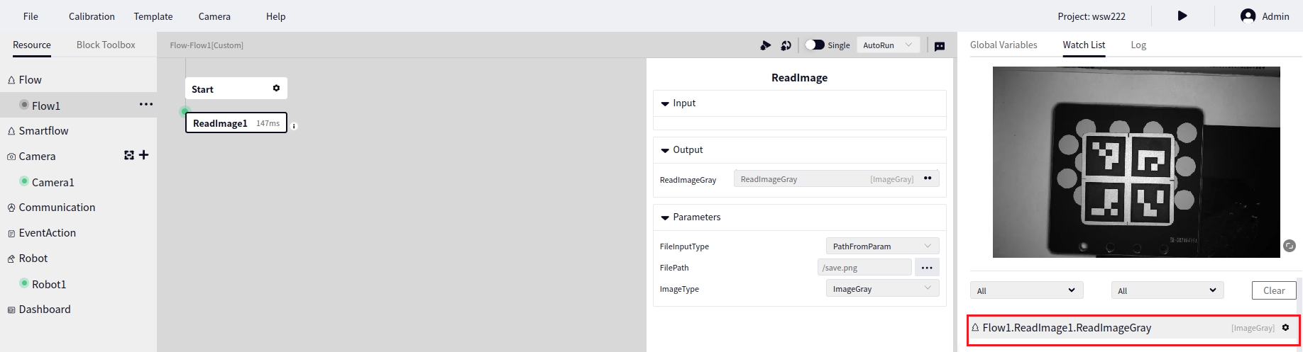
After monitoring the output of the Image Read operator in Process1 as shown above, the variable’s name will appear in the watch list. Click on the variable to view its content as shown below.
You can cancel the monitoring of a variable by clicking Monitor again in the operator’s output or by clicking the settings button on the right side of the variable in the watch list and selecting Disable, as shown below.
Watch Global Variables#
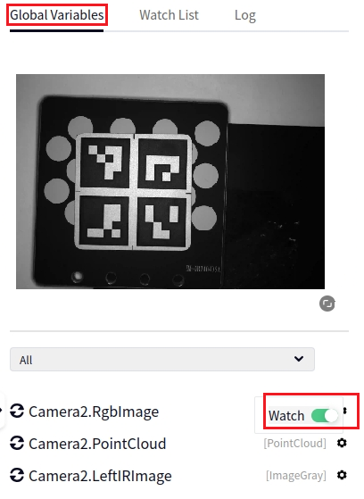
Click the settings button to the right of the global variable you want to monitor, then click Monitor to add that variable to the watch list. If you click Monitor again, the variable will be removed from the watch list, as shown below.
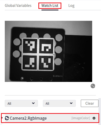
In the image above, Camera1.rgb from the Global Variables Table has been added to the Watch List.
Image Viewing#
2D Image Viewing#
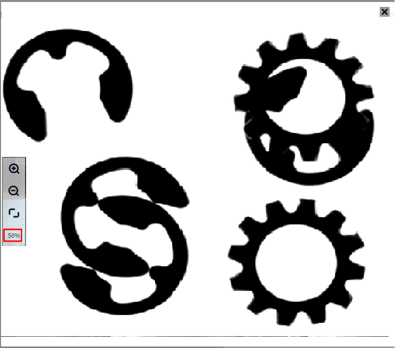
As shown below, you can set the image quality percentage by clicking the location indicated by the arrow when viewing 2D images. The lower the quality percentage, the faster the display, but the image may become distorted.
3D Image Viewing#
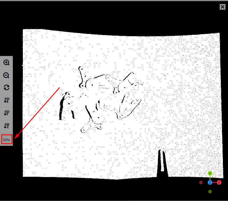
As shown below, you can set the image quality percentage by clicking the location indicated by the arrow when viewing 3D images. The lower the quality percentage, the faster the display, but the number of points in the point cloud data will correspondingly decrease.
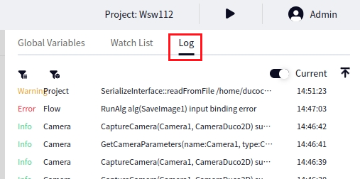
Log Dashboard#
Click on Logs on the right to access the log dashboard, as shown in the figure below
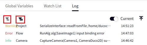
There are two filter buttons in the upper left corner of the log dashboard. From left to right, the first one is Filter by Log Level, and the second one is Filter by Module, as shown in the figure below
When the log dashboard is opened, it defaults to Real-time log mode. Click the Real-time button to switch the log mode to Historical mode, as shown in the figure below
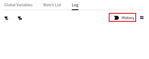
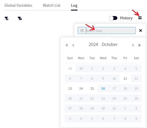
After switching the logs to Historical mode, you can select the date of the historical logs you want to view. Click on the area shown in the figure below
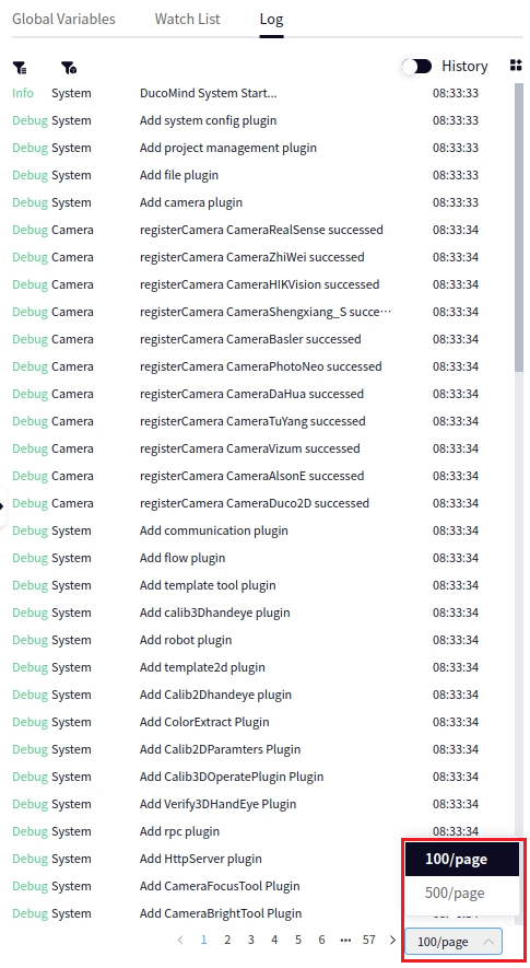
After selecting the logs for a certain date, you can click 100/page or 500/page in the lower right corner to switch the number of logs displayed currently, or you can click the buttons for the previous or next page to navigate through the pages, as shown in the figure below
Tools#
2D Template Creation#
Entry#
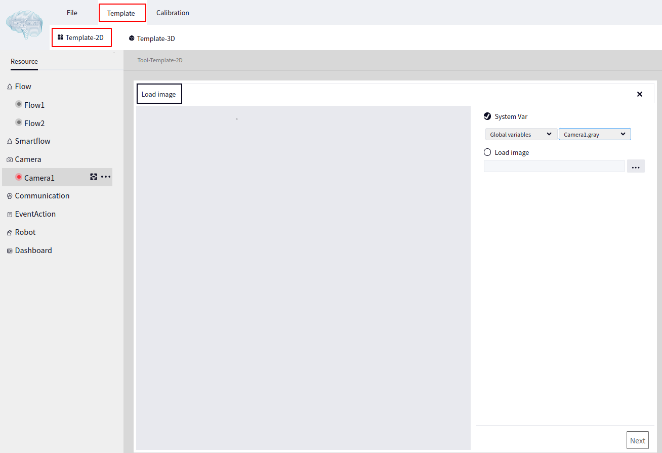
By clicking Template Tool and 2D Template Creation successively, you can reach the 2D Template Creation tool interface, as shown in the image below:
Load Image#
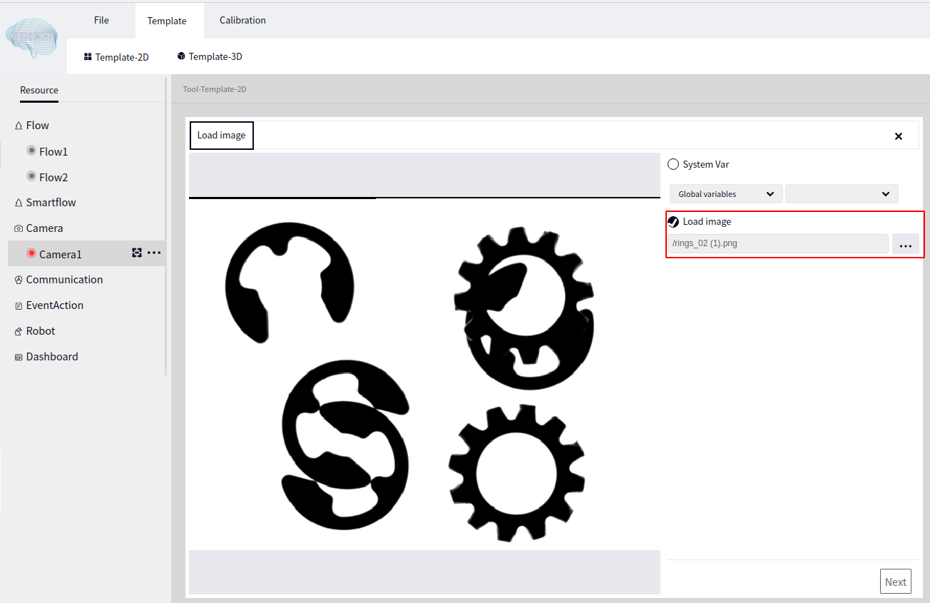
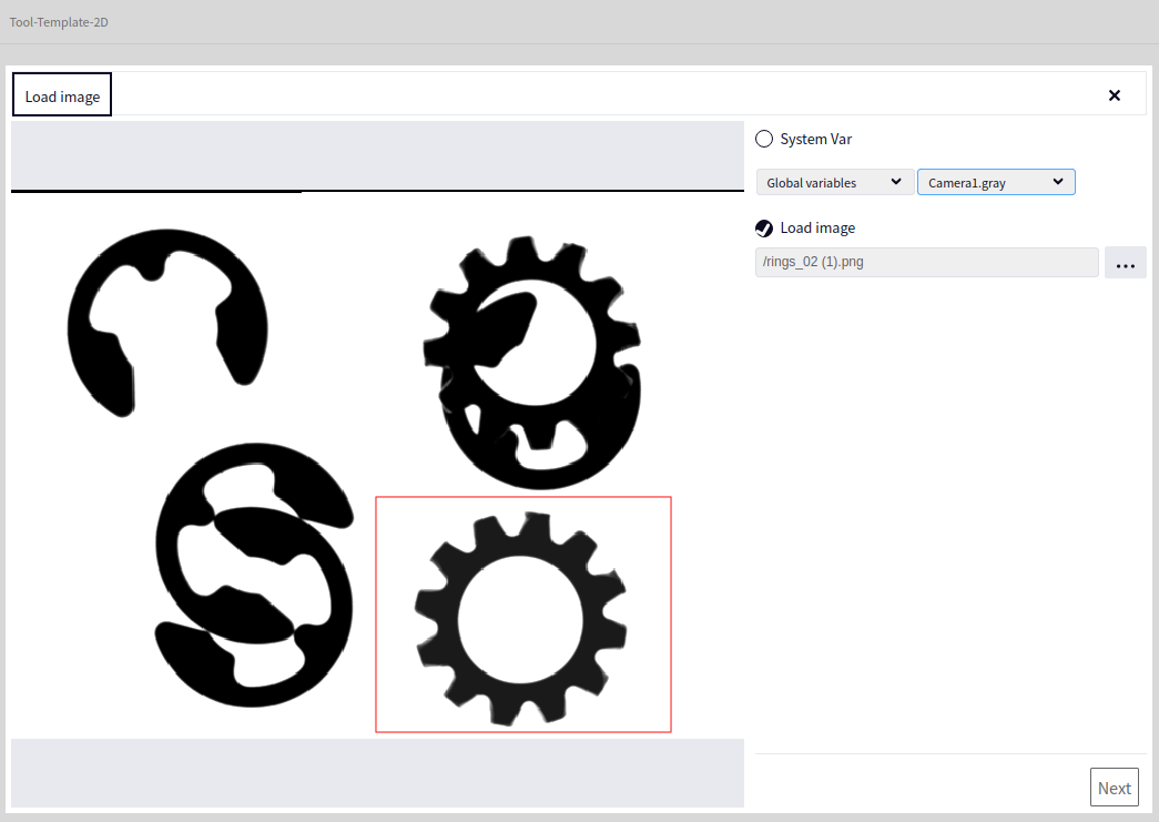
To load an image, you can choose either System Variable or Load Image. System Variable allows you to select images from Global Variable Table or Watch List, while Load Image lets you load an image from a local path. The image below shows the result of loading a local image:
Draw ROI#
After loading an image, move the mouse to the left side of the image to display the toolbar, as shown in the image below:
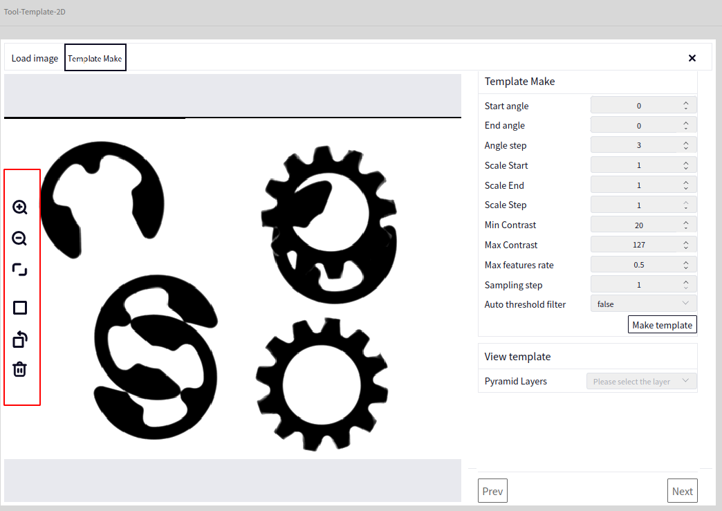
The meanings of the icons in the toolbar from top to bottom are: Zoom In, Zoom Out, Reset Image, Rectangle ROI, Rotated Rectangle ROI, Delete Drawn ROI
We can use Rectangle ROI to draw a rectangular region as needed, as shown below:
Template Creation#
On the basis of the above image, click Next Step to reach the following interface:
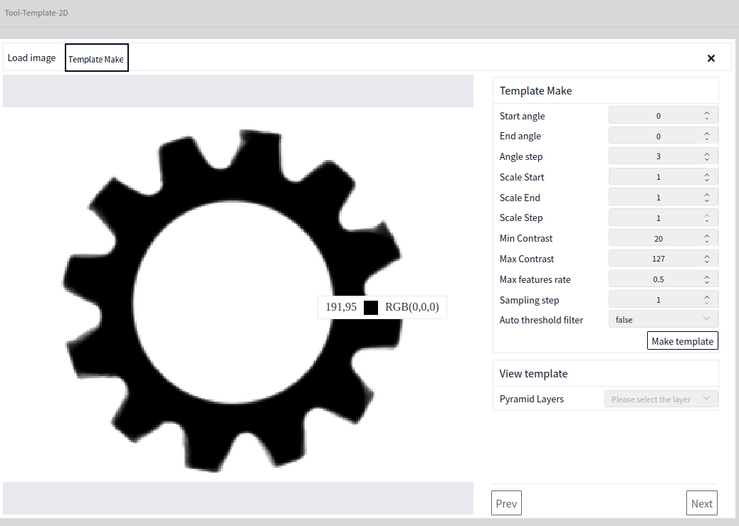
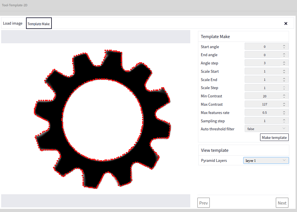
Before creating the template, you can set some parameters as needed. After setting the parameters, click Create Template to see the effect of template creation, as shown below:
Template View#
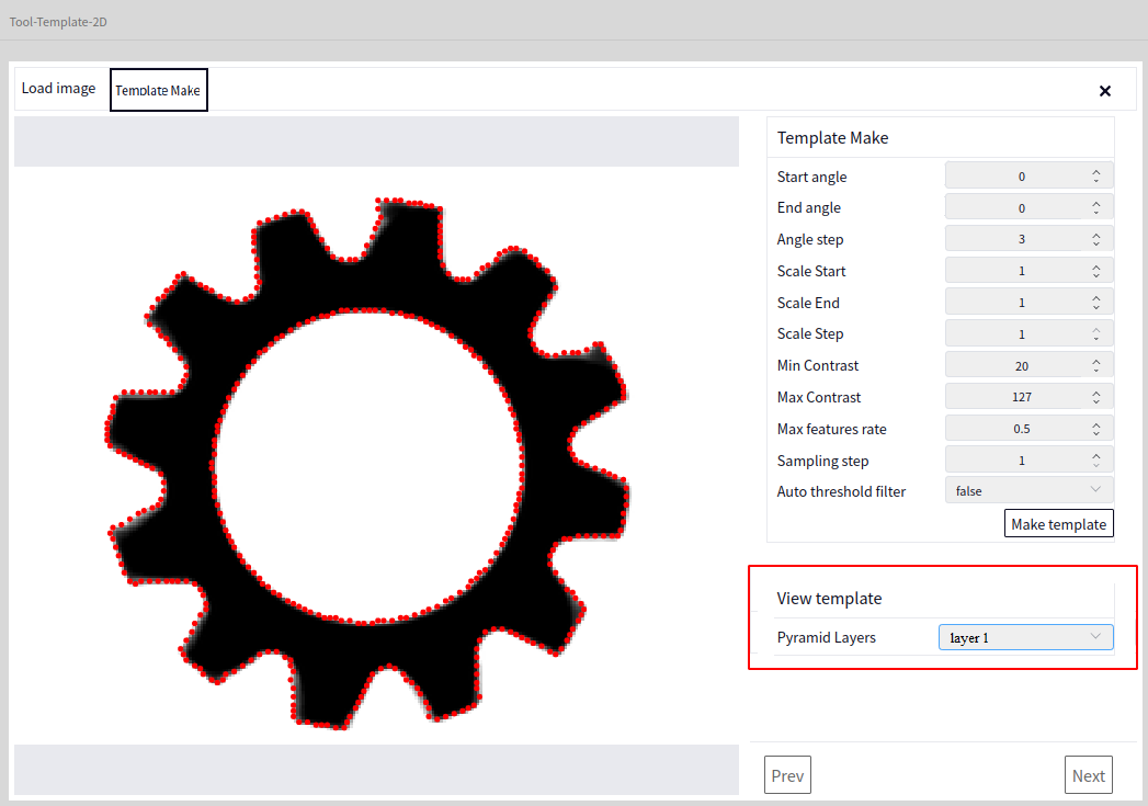
After creating the template, you can view the created template’s effect by Pyramid Layers. There are a total of 8 pyramid layers, with the first layer as the default, as shown below:
Mask Creation#
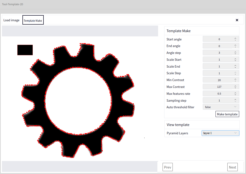
After the template is created, you can select Rectangle ROI or Rotated Rectangle ROI from the image’s left toolbar to create a mask. The purpose is to cover any excess points. You can skip this step if there are no excess points to be removed, as shown below:
Save Template#
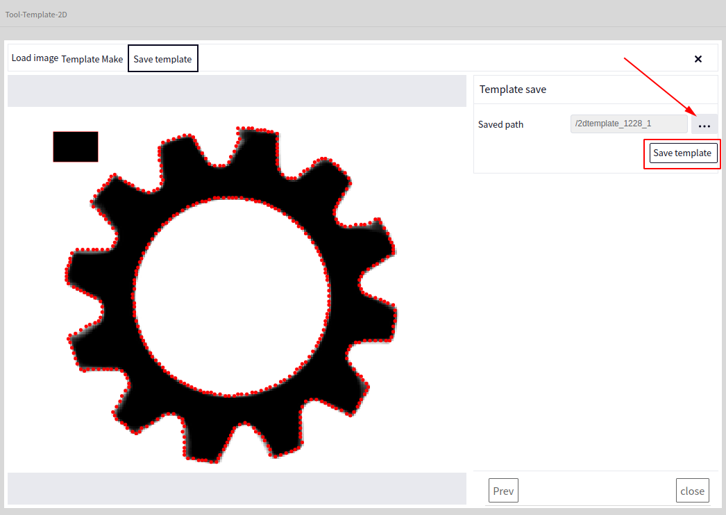
After creating the template, click the next step to display the save template interface. Click where the arrow points in the image below to input the template name and choose the save path, then click save template:
Tip
When you click save template, a success message will pop up upon successful save, and the saved template will automatically append the suffix .dmtemp
3D Template Creation#
Entry#
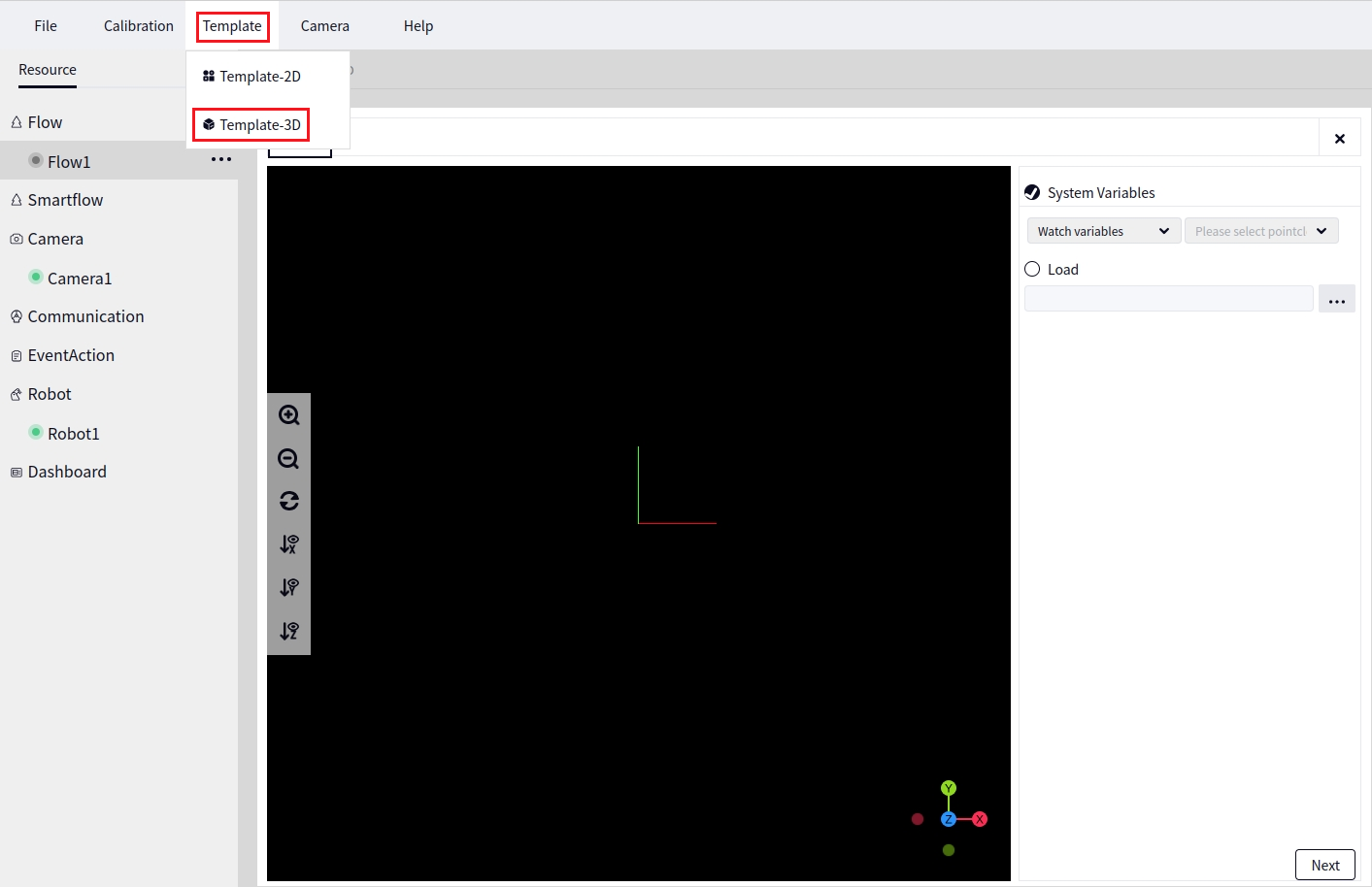
Click Template Tools followed by 3D Template Creation to enter the 3D Template Creation tool interface, as shown below:
Load Point Cloud#
You can choose System Variables or Load Point Cloud to load the point cloud. System Variables allows you to select point clouds from the Global Variable Table or Watch List. Load Point Cloud allows you to load a point cloud from a local path. Below is the result of loading a local point cloud:
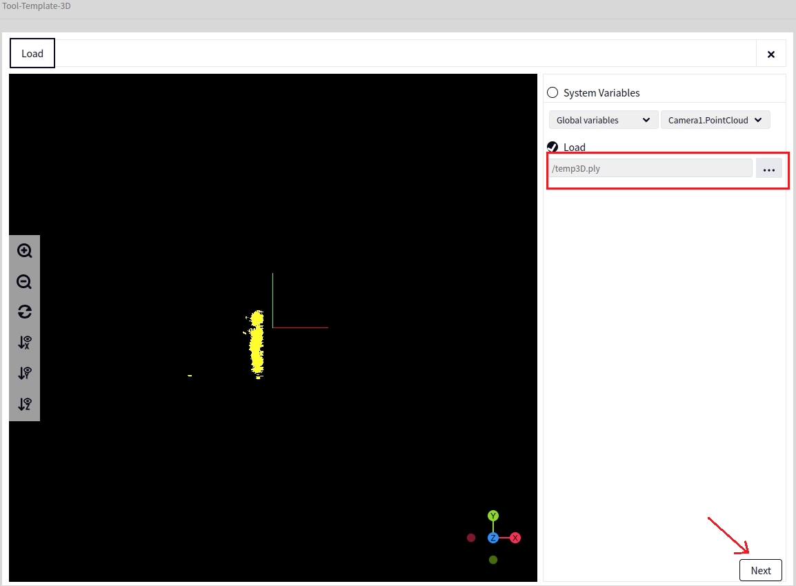
Tip
When loading point clouds, only point clouds with the ply suffix can be loaded from the local system.
Point Cloud Trimming#
Click on next to switch to the point cloud trimming interface, as shown below:
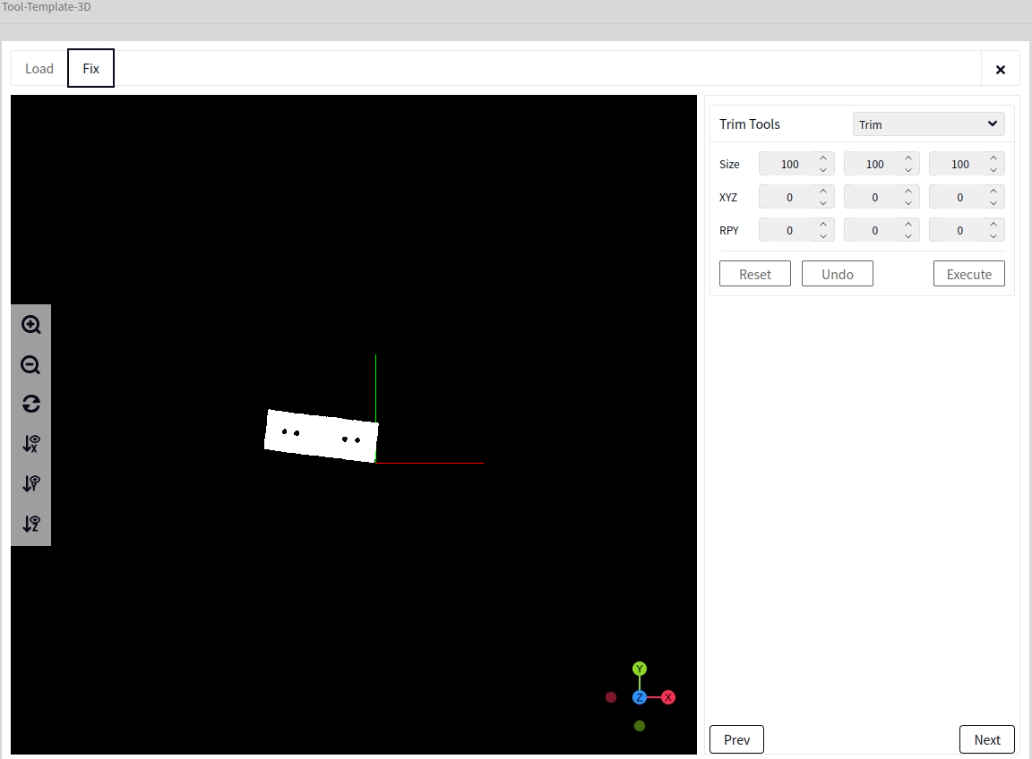
Click Execute and View to see the effect of the current tool execution. Click Undo to undo the previous operation. Click Reset to return to the original state.
The default point cloud trimming tool is Crop, but you can also choose from the following tools from the dropdown menu: Move, Auto Reset Center, Filter, and Downsample.
Crop#
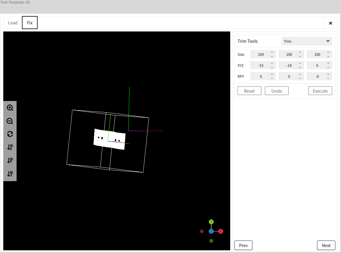
If the point cloud area unrelated to the template point cloud is too large, unnecessary point clouds can be cropped.
Click the center of the template point cloud. The interface will display the coordinates of the point. Input these coordinates into XYZ;
Enter the size of the area along the XYZ directions from step 1 in the Size field. After entering the size, you can see the rectangular effect. Adjust the size if it is inappropriate;
If the angle of the cuboid to be cropped deviates significantly from the template, input the angle of the cropping area along the XYZ directions in RPY and adjust as necessary to see the effect.
Move#
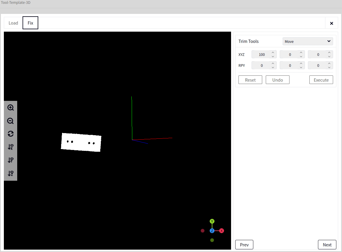
xyz: Indicates the distance to move the template point cloud along the XYZ axes.
RPY: Indicates the angle to offset when moving the template point cloud along the XYZ axes.
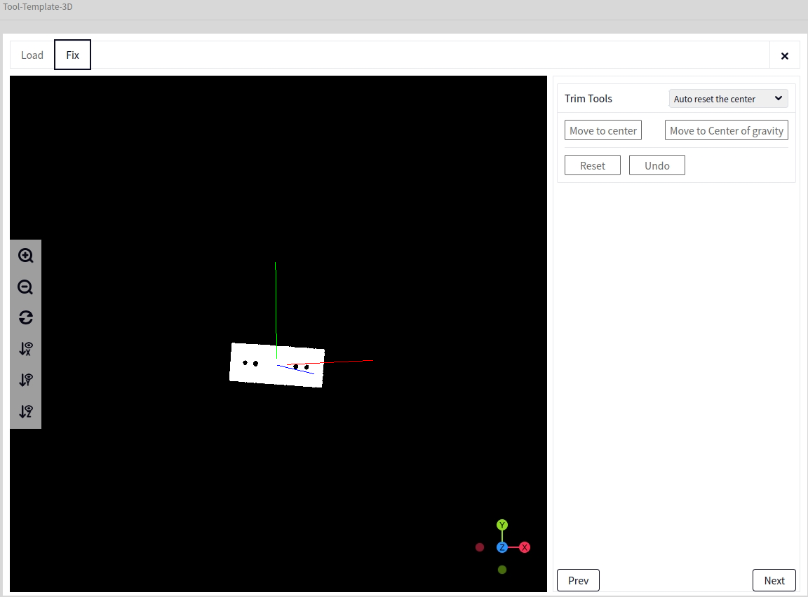
Auto Reset Center#
Move to Center of Mass: Moves the template to the origin (0,0,0) of the spatial coordinate system.
Move to Geometric Center: Moves the template to the origin (0,0,0) of the spatial coordinate system.
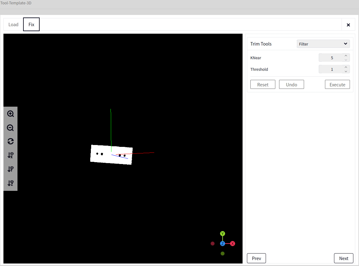
Filter#
Set K Nearest Neighbor and Threshold then click Execute and View to see the point cloud filtering effect.
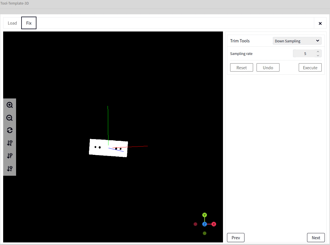
Downsample#
When the point cloud density is too high, setting the sampling precision can appropriately reduce the quality of the point cloud, somewhat speeding up the program.
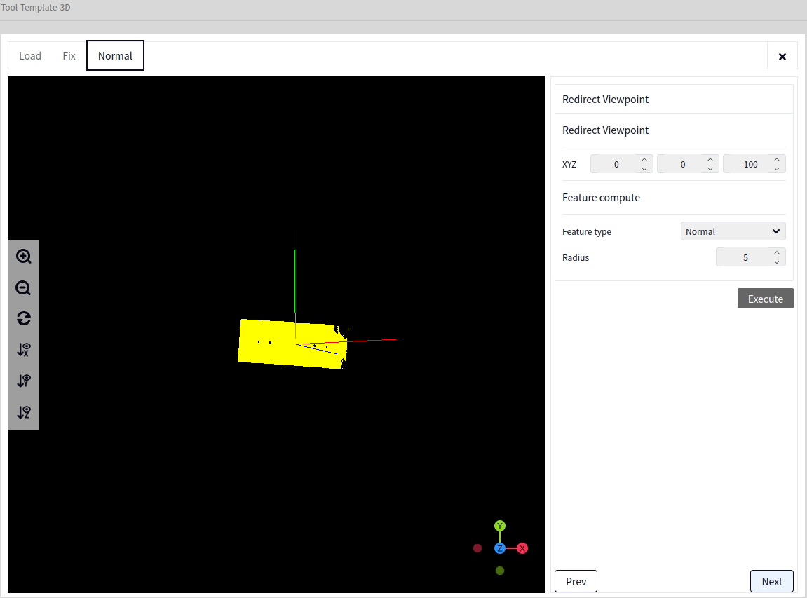
Viewpoint Redirection#
In this interface, set the Z value in XYZ to -100, select Normal for Feature Type, choose a radius of 5, and click Execute and View, as shown below:
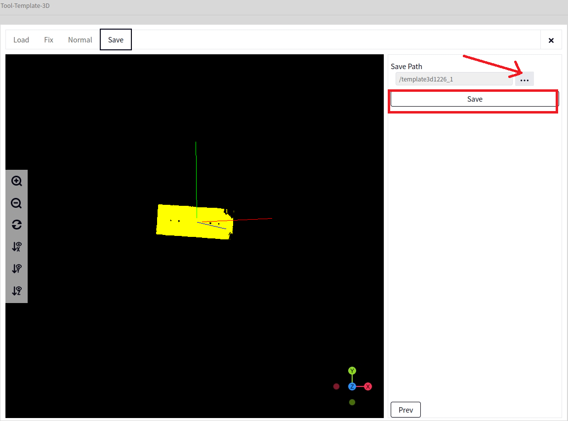
Save Template#
After Normal Modification, click next (based on the above diagram) to switch to the Save Template interface. Click on the arrow shown below to choose the file name and path for saving, then click Save Template.
Tip
When you click save template, a success message will pop up on successful save, and the saved template will automatically append the suffix .dmtemp.
Intrinsic Calibration#
Entry#
Click Calibration Tools followed by Intrinsic Calibration to reach the Intrinsic Calibration tool interface, as shown below
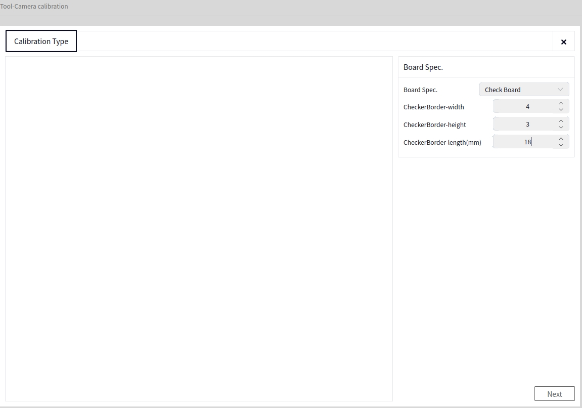
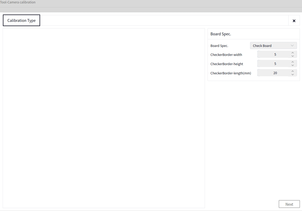
Calibration Board Specification Settings#
Set Width, Height, and Edge Length according to the specifications of the calibration board currently in use, as shown below
Add Data#
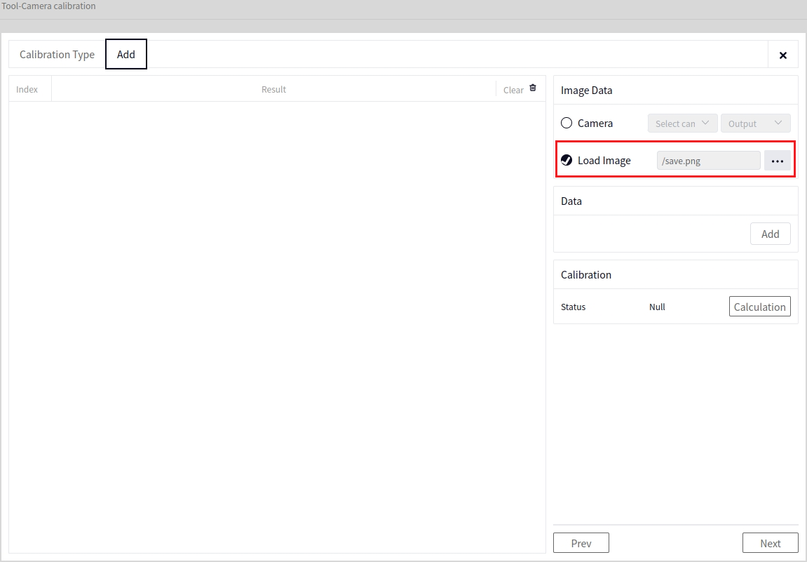
Image Data#
Choose one from Camera Data or Load Image. Camera Data allows selection of image data from the connected camera, while Load Image allows loading of local images. The image below shows the result after selecting Load Image
Calibration Data#
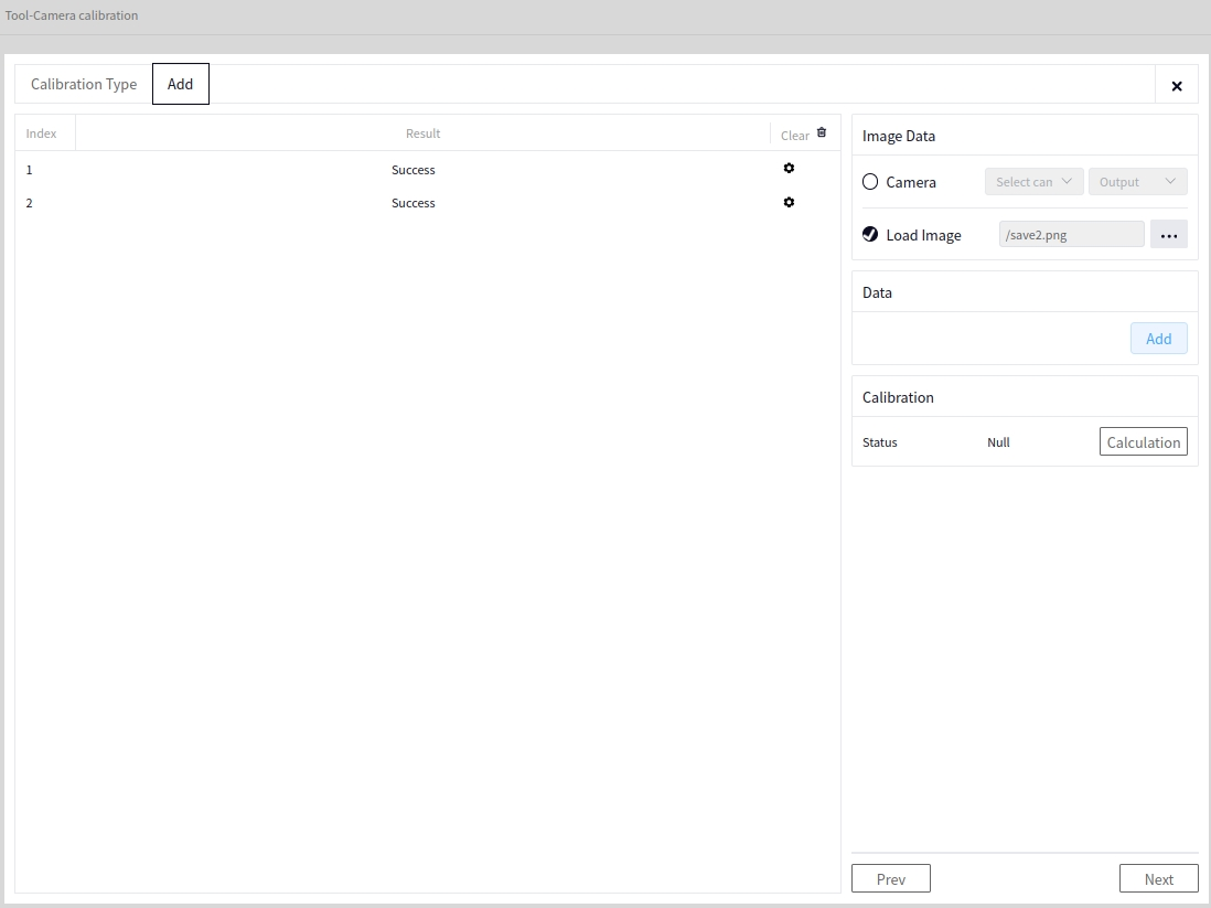
Click the Add Data button, and the results will be displayed on the left. The image below shows the result after successfully adding two pieces of data.
Tip
A pop-up error message will appear if data addition fails, mostly due to unclear images or mismatched calibration board specifications.
View or Delete Data#
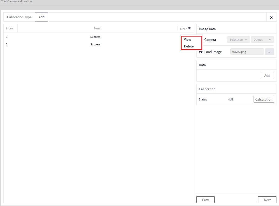
Click the settings button next to a piece of data to show the View Data and Delete buttons, as shown below
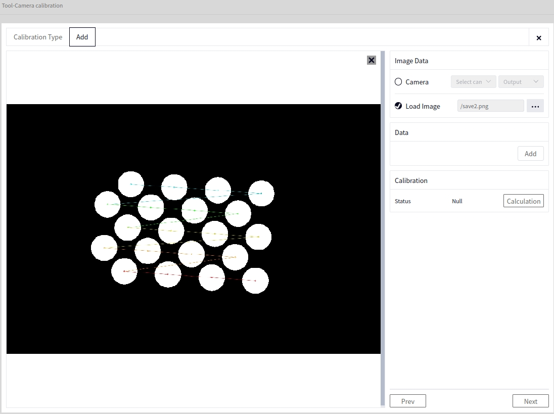
The interface after clicking the View Data button is shown below:
Click the Delete button to delete the selected data.
Calibration Calculation#
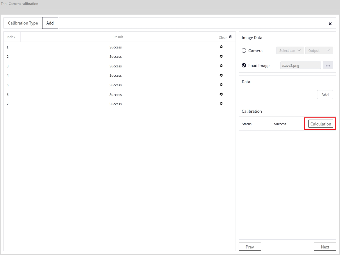
Click the Calibration Calculation button to perform calibration calculation. Success or failure will be displayed on the interface, as shown below
Save File#
After Calibration Calculation, click Next to set the file name and path for saving as indicated by the arrow in the image below, then click save file.
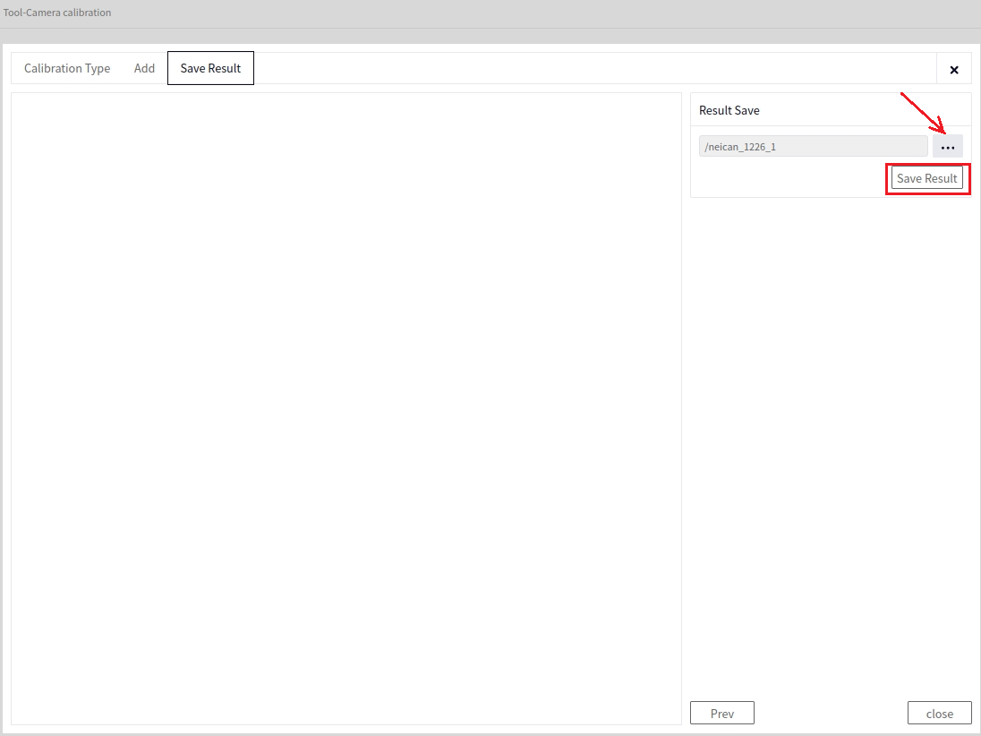
Tip
After clicking save file, a success message will pop up if the save is successful, and the saved file will automatically have the suffix .dmcalib appended to it.
3D Hand-Eye Calibration#
Entry#
Click Calibration Tool and then 3D Hand-Eye Calibration to reach the 3D Hand-Eye Calibration tool interface, as shown below.
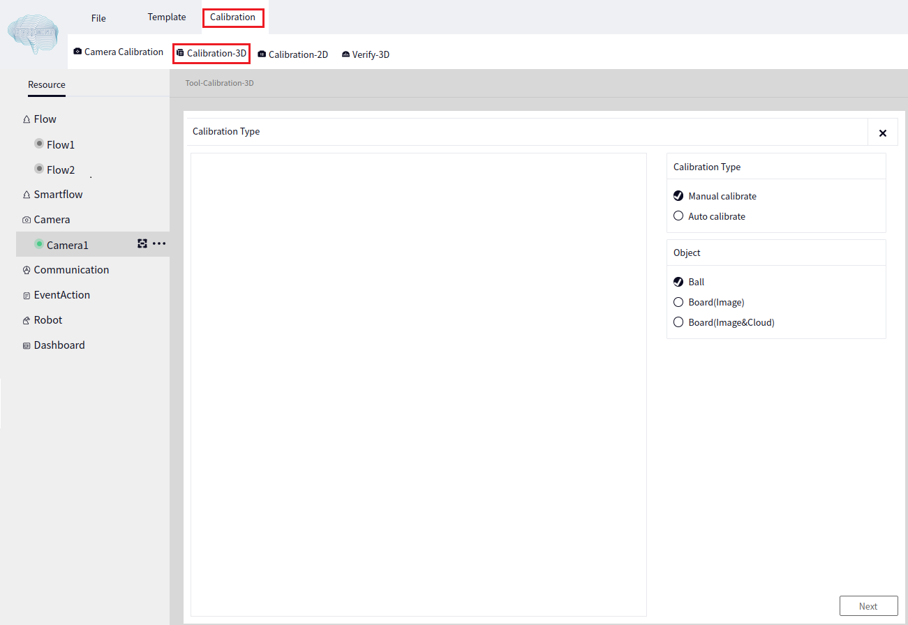
Calibration Sphere#
Manual Calibration#
After entering the 3D Hand-Eye Calibration interface, select Manual Calibration in the Calibration Method, and choose Calibration Sphere in the calibration object, as shown below.
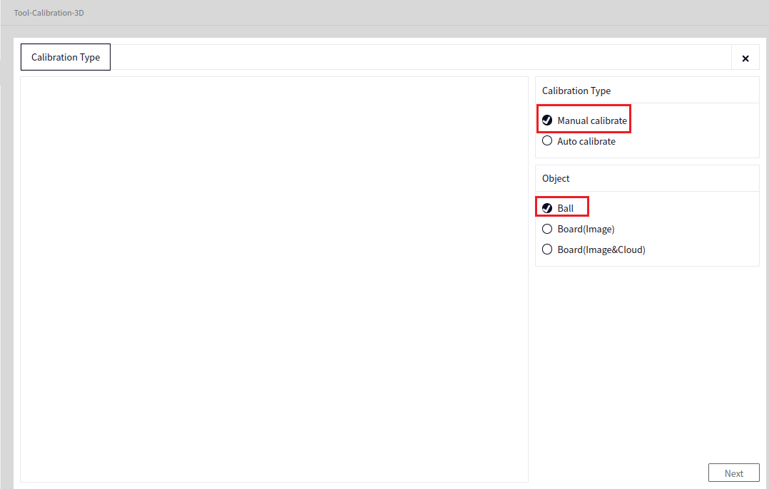
After clicking “Next” based on the above image, you will enter the following interface.
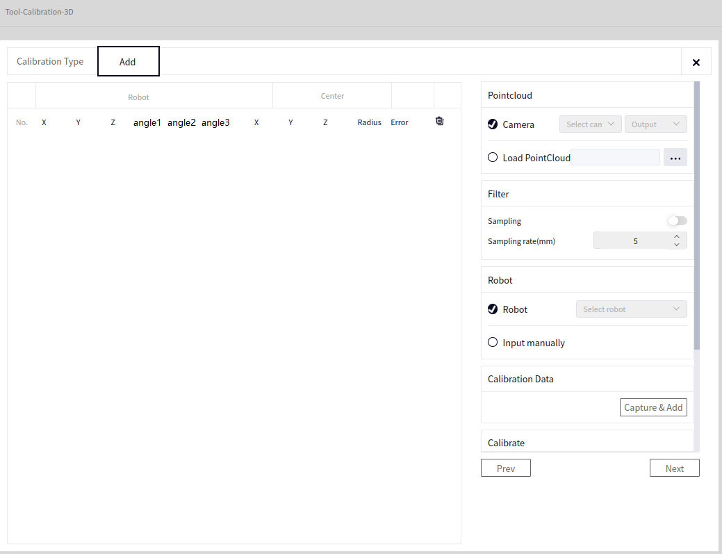
In the image above: - Point Cloud Data (Choose one):
Camera Data: Select the point cloud data from the locally connected camera.
Load Point Cloud: Read a point cloud in ply format from a local path.
- Point Cloud Filtering:
Point Cloud Sampling: Represents point cloud downsampling. When the toggle switch is moved to the right, downsampling is enabled; when moved to the left, it is disabled. The image above shows it as disabled.
Sampling Precision: The higher the precision, the lower the quality of the output point cloud.
- Robot Data (Choose one):
Robot: Select the locally connected robot.
Manual Input: Manually input the robot’s pose each time the robot is moved. After the data is successfully added, it will appear under Robot data in the left-hand data panel.
Take a Photo and Add Data#
After setting the parameters, click the Take Photo and Add Data button. After clicking, the Calibration Sphere Recognition interface will appear, as shown below.
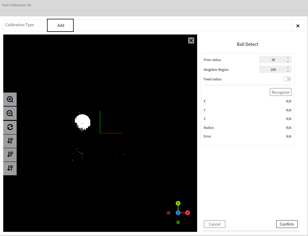
Calibration Sphere Recognition#
- In the image above:
The left side of the interface is the Point Cloud Browser, displaying the Point Cloud of the Calibration Sphere. At this point, you need to click the center of the calibration sphere (approximately) with the mouse.
Prior Radius: The current radius of the calibration sphere.
Neighborhood Range: Indicates the number of points selected around the center of the sphere during calibration.
Fixed Radius: The image above shows the fixed radius as enabled (default is disabled). The switch to the right indicates enabled. If disabled, the prior radius will be optimized. If enabled, the prior value of the radius will be used to calculate the center coordinates of the sphere.
Click recognize, and if successful, the recognized sphere will be displayed in the left area, with the corresponding XYZ, radius, and error shown below, as in the image below.
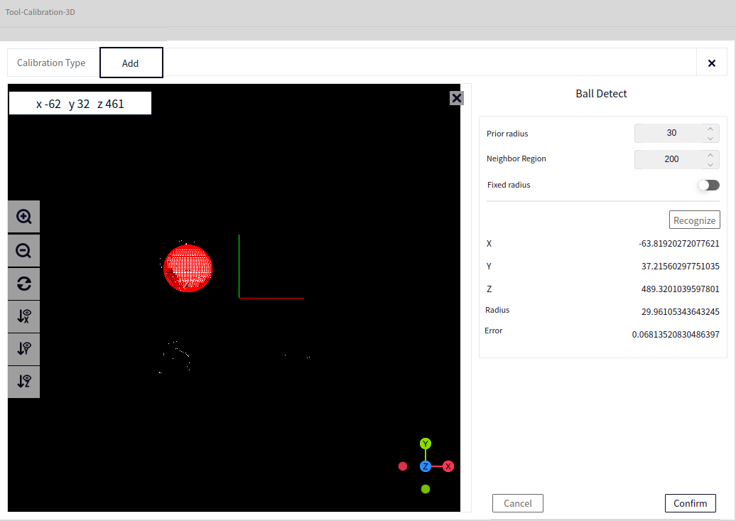
Tip
If recognition fails, an error message will pop up. In this case, adjust the parameters or the camera position.
After recognition is complete, click the Confirm button to successfully add a data point and return to the previous interface, as shown below.
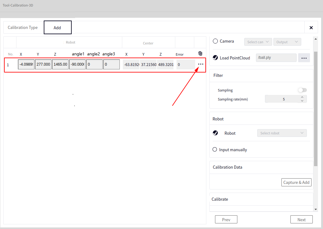
The red box in the image above indicates the data just added. Robot Data represents the current pose of the robot, Sphere Center represents the recognized center of the sphere, and Error will be updated after Calibration Calculation.
- Clicking the arrow in the image above will bring up the View Data and Delete buttons (these buttons are also available in automatic calibration).
View Data: View the point cloud data of the calibration sphere.
Delete: Delete the current row of data (this can be done if the calibration error is too large).
Tip
After successfully adding one set of data, you can move the robotic arm so that the camera and the calibration sphere are in different poses, ensuring that the calibration sphere remains within the camera’s field of view (generally, 15 poses are selected). After moving the robotic arm, click Take Photo and Add Data again to see if recognition is successful.
Automatic Calibration#
After entering the 3D Hand-Eye Calibration interface, select Automatic Calibration in the Calibration Method, and choose Calibration Sphere in the calibration object, as shown below.
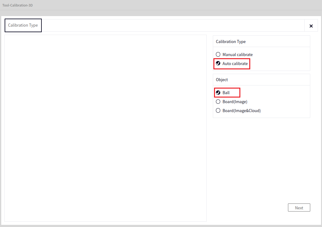
After clicking “Next” based on the above image, you will enter the following interface.
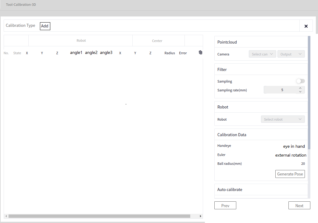
At this point, Point Cloud Data can only be selected from the Point Cloud Data of the connected camera, and Robot Data can only be selected from the locally connected robot. The operation of Point Cloud Downsampling is the same as in Manual Calibration.
Generate Pose#
Click the Generate Pose button to enter the Generate Pose interface, as shown below.
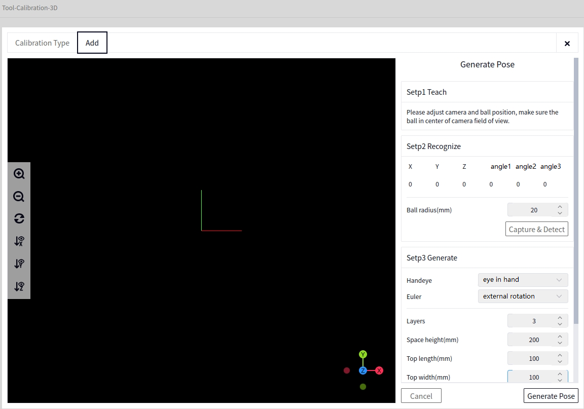
Set the radius of the calibration sphere (in mm) according to the actual situation.
Tip
After setting the radius, click Take Photo and Recognize to check whether the left-side point cloud browser successfully identifies the sphere. If there is no change on the left side or an error message pops up, check whether the Calibration Sphere Radius is set correctly and whether the calibration sphere is directly below the camera.
Once Take Photo and Recognize is successful, you can set the parameters for generating the pose according to the actual situation, as shown below.
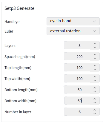
After setting the parameters, click Generate Pose. The result of generating the pose will be approximately as shown below.
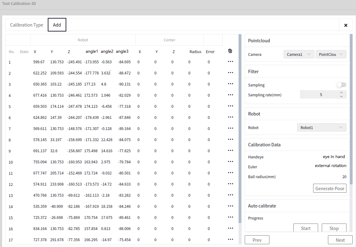
Caution
After generating the pose, it is recommended to check whether each row of the robot’s pose is normal. If the values are too large, adjust the parameters for generating the pose and regenerate the pose. It is recommended to set the robot’s movement speed to a lower value before starting calibration.
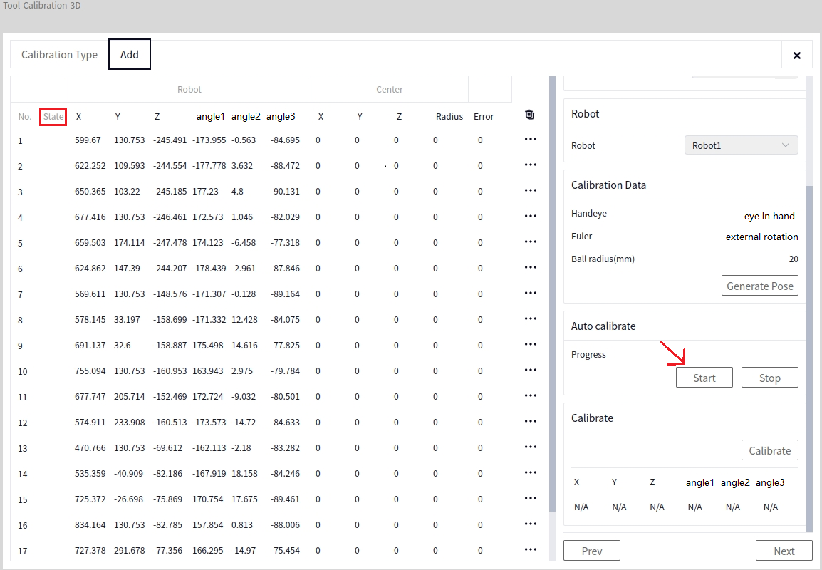
Start Calibration#
Once the generated poses are confirmed to be correct, click Start Calibration. The robot will automatically move to each pose and perform the calibration. The result of each row’s calibration will be displayed in the Status column.
Calibration Calculation#
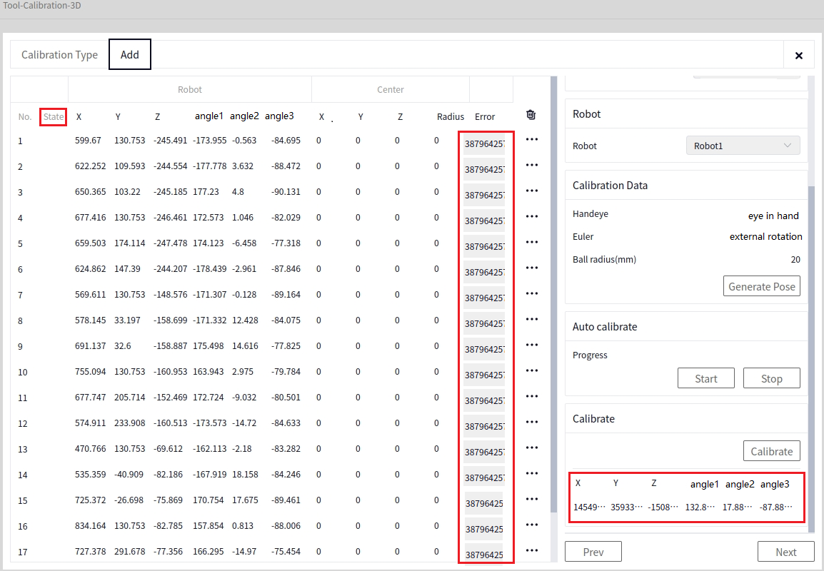
After Manual Calibration or Automatic Calibration, click Calibration Calculation. Once the calibration calculation is successful, the error for each row of data and the pose below the calibration calculation will be displayed, as shown below.
Tip
At least 5 sets of data are required to perform the calibration calculation. You can delete some data with larger errors after the calibration calculation.
Save#
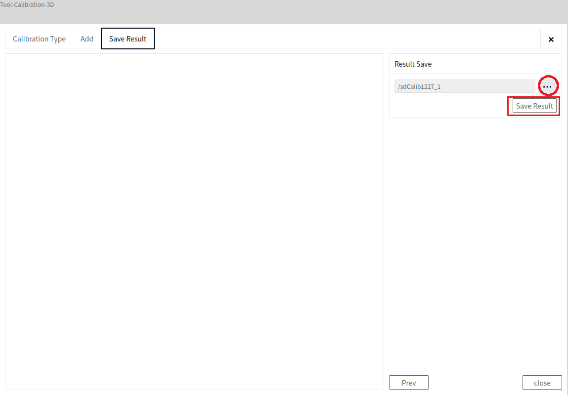
After the Calibration Calculation, click Next to reach the Save data interface. Click the arrow in the image below to choose the file name and path to save, then click Save File.
Tip
The saved file will automatically append the suffix .dmcalib.
Calibration Plate (Image-Based)#
Manual Calibration#
After entering the 3D Hand-Eye Calibration interface, select Manual Calibration in the Calibration Method, and choose Calibration Plate (Image-Based) in the calibration object, as shown below.
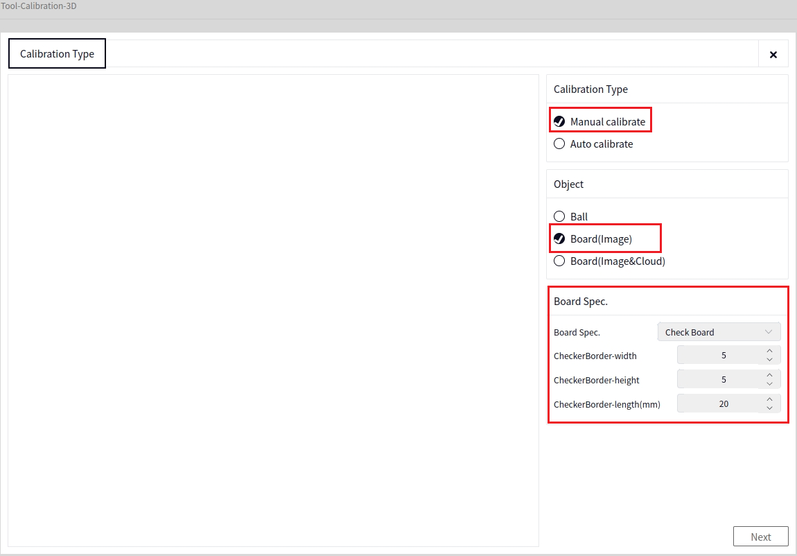
In the image above, set the Calibration Plate Specifications according to the actual situation, then click Next to enter the following interface.
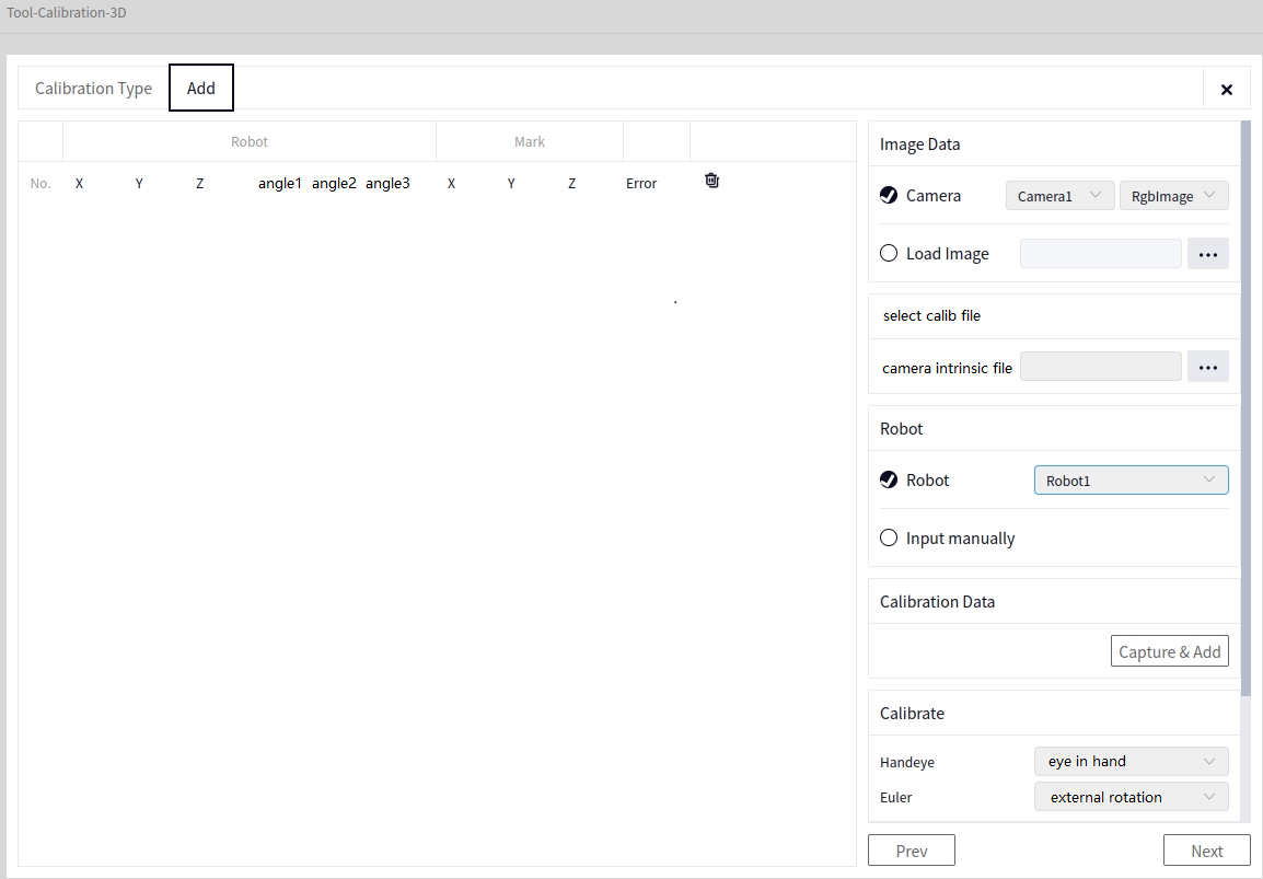
- In the image above:
- Image Data (Choose one):
Camera Data: Select the 2D image data from the locally connected camera.
Load Image: Read a 2D image from a local path.
- Calibration File Selection:
Intrinsic Calibration File: Choose a file saved using the Intrinsic Calibration tool from the local system. The file format is xxx.dmcalib.
- Robot Data (Choose one):
Robot: Select the locally connected robot.
Manual Input: Manually input the robot’s pose each time the robot is moved. After the data is successfully added, it will appear under Robot data in the left-hand data panel.
Take a Photo and Add Data#
After setting the parameters, click the Take Photo and Add Data button. If the data is successfully added, a new data entry will appear in the left-hand data panel. If it fails, a pop-up window will appear. Before adding each data point, manually move the robot to different poses above the calibration plate. The image below shows the result after adding 5 data points.
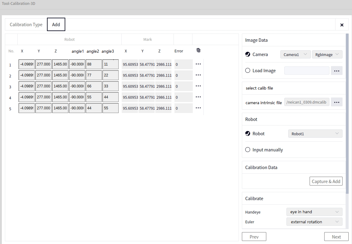
Automatic Calibration#
After entering the 3D Hand-Eye Calibration interface, select Automatic Calibration in the Calibration Method, and choose Calibration Plate (Image-Based) in the calibration object, as shown below.
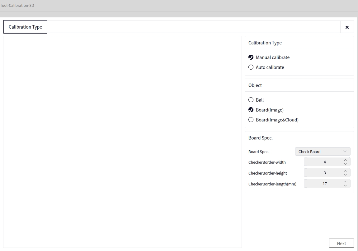
In the image above, set the Calibration Plate Specifications according to the actual situation, then click Next to enter the following interface.
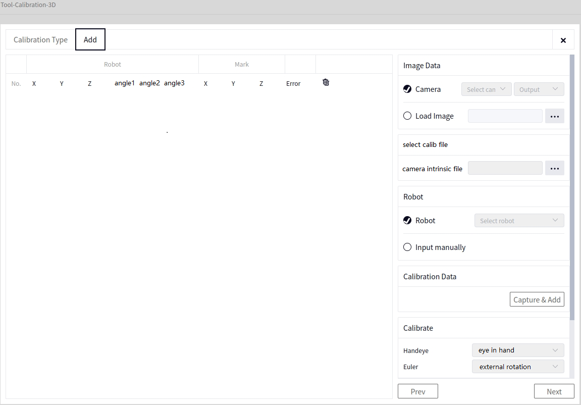
At this point, Image Data can only be selected from the Image Data of the connected camera, and Robot Data can only be selected from the locally connected robot. The method for selecting the Intrinsic File is the same as in Manual Calibration.
Generate Pose#
The method for generating the pose is the same as in Automatic Calibration for the Calibration Sphere.
Tip
Click Take Photo and Recognize to check whether the left side successfully displays the calibrated result. If there is no change on the left side or an error message pops up, check whether the calibration plate is in the correct position.
Start Calibration#
Same as Start Calibration under Automatic Calibration for the Calibration Sphere.
Calibration Calculation#
After Manual Calibration or Automatic Calibration, click Calibration Calculation. Once the calibration calculation is successful, the error for each row of data and the pose below the calibration calculation will be displayed, as shown below.
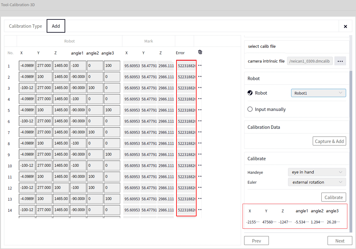
Tip
At least 5 sets of data are required to perform the calibration calculation. You can delete some data with larger errors after the calibration calculation.
Save#
After the Calibration Calculation, click Next to reach the Save data interface. Click the arrow in the image below to choose the file name and path to save, then click Save File.
Tip
The saved file will automatically append the suffix .dmcalib.
Calibration Plate (Image and Point Cloud-Based)#
Manual Calibration#
After entering the 3D Hand-Eye Calibration interface, select Manual Calibration in the Calibration Method, and choose Calibration Plate (Image and Point Cloud-Based) in the calibration object, as shown below.
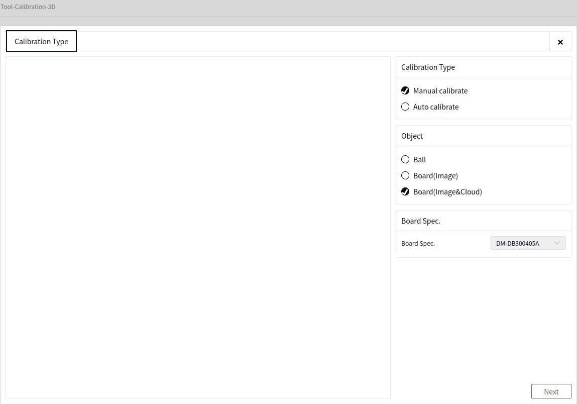
After clicking “Next” in the image above, you will switch to the following interface.
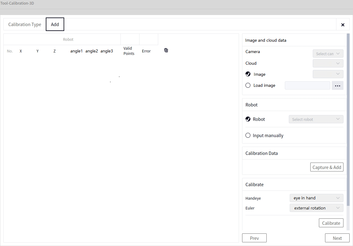
- In the image above:
Camera: Select the locally connected camera (3D camera).
Point Cloud Data: Select the point cloud data of the camera.
- Image Data (Choose one):
Camera Data: Select the 2D image data from the locally connected camera.
Load Image: Read a 2D image from a local path.
- Robot Data (Choose one):
Robot: Select the locally connected robot.
Manual Input: Manually input the robot’s pose each time the robot is moved. After the data is successfully added, it will appear under Robot data in the left-hand data panel.
Take a Photo and Add Data#
After setting the parameters, click the Take Photo and Add Data button. If the data is successfully added, a new data entry will appear in the left-hand data panel. If it fails, a pop-up window will appear. Before adding each data point, manually move the robot to different poses above the calibration plate.
Automatic Calibration#
After entering the 3D Hand-Eye Calibration interface, select Automatic Calibration in the Calibration Method, and choose Calibration Plate (Image and Point Cloud-Based) in the calibration object, as shown below.
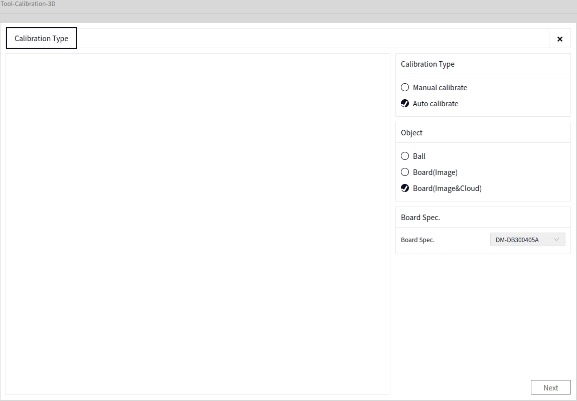
After clicking Next based on the above image, you will enter the following interface.
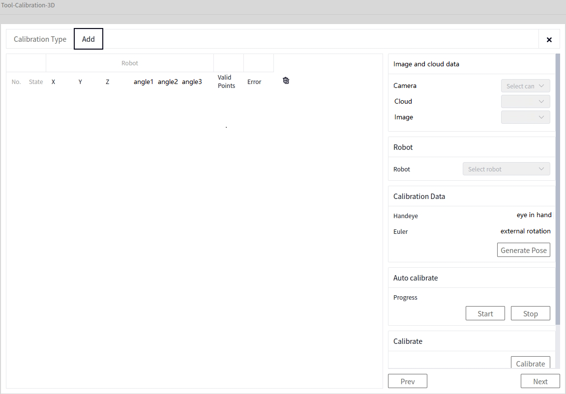
At this point, Image Data can only be selected from the Image Data of the connected camera, and Robot Data can only be selected from the locally connected robot.
Generate Pose#
The method for generating the pose is the same as in Automatic Calibration for the Calibration Sphere.
Tip
Click Take Photo and Recognize to check whether the left side successfully displays the calibrated result. If there is no change on the left side or an error message pops up, check whether the calibration plate is in the correct position.
Start Calibration#
Same as Start Calibration under Automatic Calibration for the Calibration Sphere.
Calibration Calculation#
After Manual Calibration or Automatic Calibration, click Calibration Calculation. Once the calibration calculation is successful, the error for each row of data and the pose below the calibration calculation will be displayed, as shown below.
Tip
At least 5 sets of data are required to perform the calibration calculation. You can delete some data with larger errors after the calibration calculation.
Save#
After the Calibration Calculation, click Next to reach the Save data interface. Click the arrow in the image below to choose the file name and path to save, then click Save File.
Tip
The saved file will automatically append the suffix .dmcalib.
12-Point Calibration#
Entry#
Click Calibration Tool and then 12-Point Calibration to enter the 12-Point Calibration tool interface, as shown below
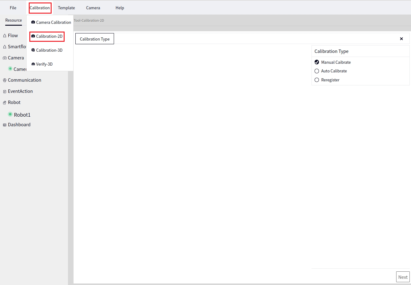
Manual Calibration#
In the Calibration Mode interface, select Manual Calibration and click Next to go to the Calibration Type settings. Set according to the actual situation, as shown below
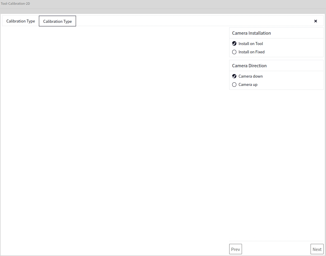
After setting the Calibration Type, click Next to display the following interface
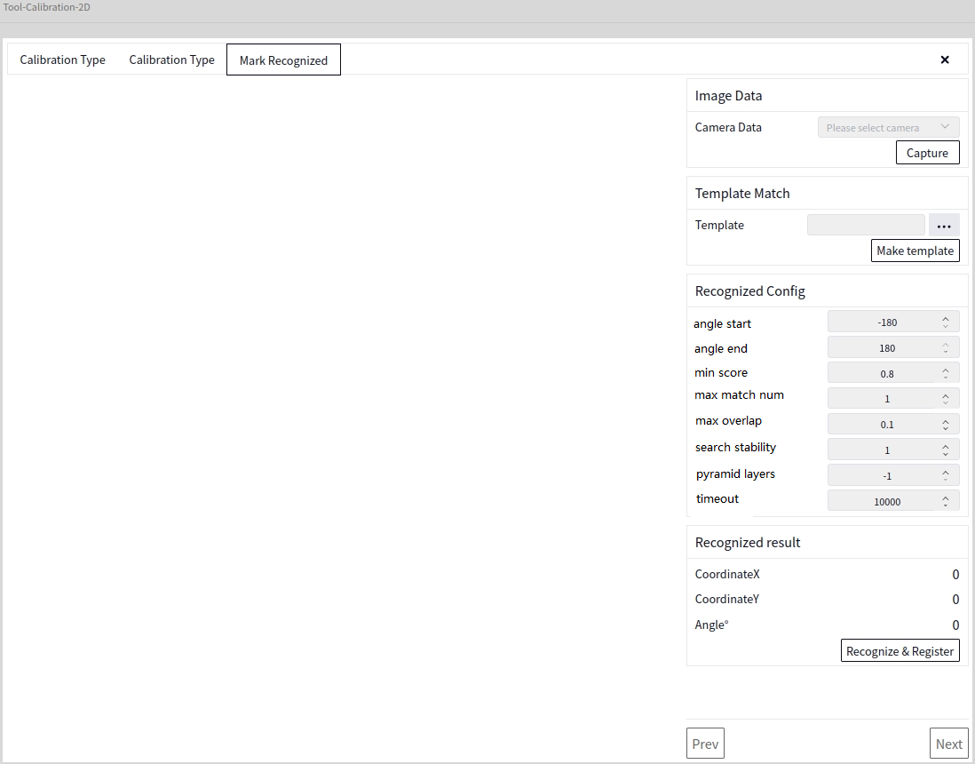
- In the above image
- Image Data:
Camera Data: Select the 2D image data of the locally connected camera
- Template Matching:
Template: Select a file saved using the 2D Template Creation tool from the local storage, the file format being xxx.dmtemp
Tip
Clicking Create Template here will directly jump to the 2D Template Creation interface
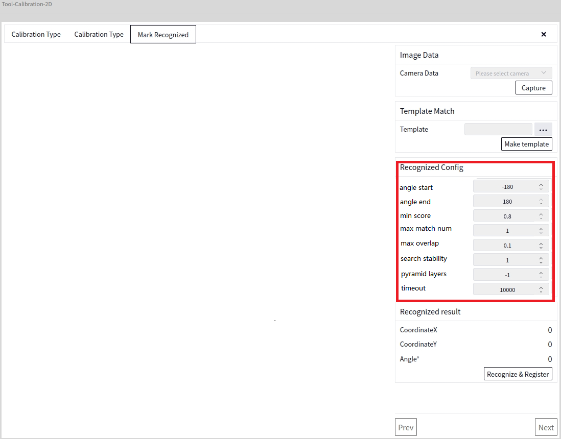
After selecting the template file, you can set the parameters under Marker Recognition Configuration, as shown below
Recognize and Set as Registration Point#
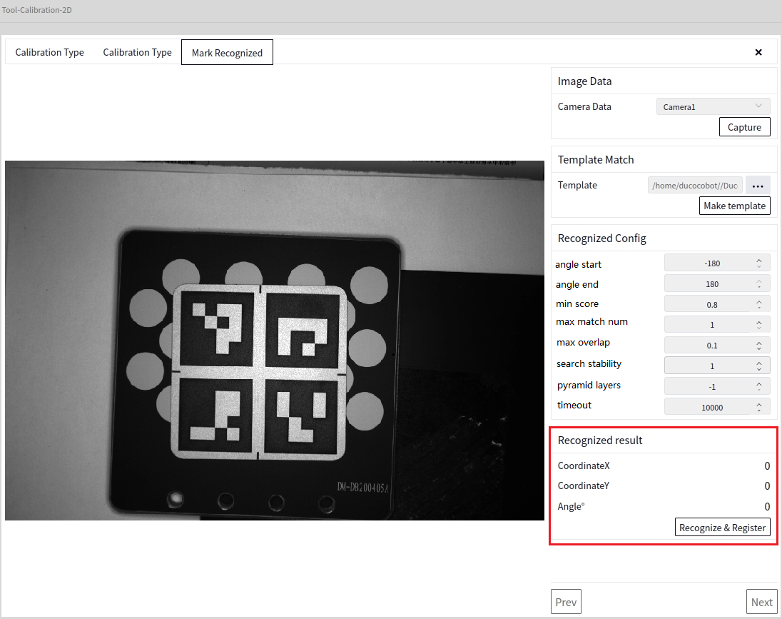
After setting the parameters, click Recognize and Set as Registration Point to see the result of the registration point, as shown below
Generate Poses#
Based on the above image, click Next to display the following interface
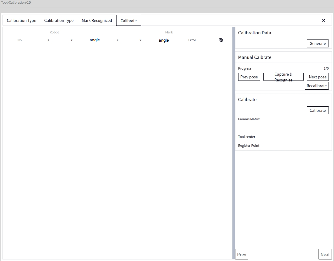
At this point, click the Generate Poses button to switch to the following interface
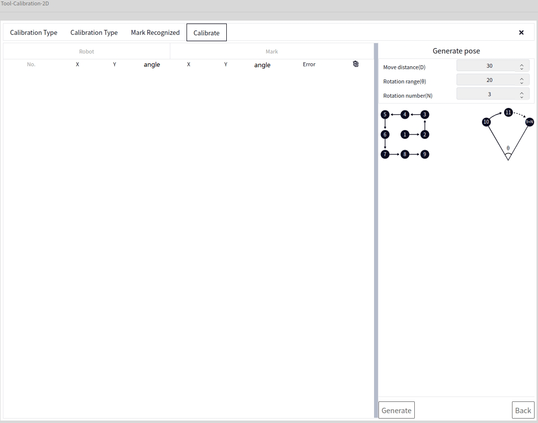
After setting the Movement Spacing, Rotation Range, and Number of Rotation Points, you can click Generate Poses. The poses generated based on the above results are as follows
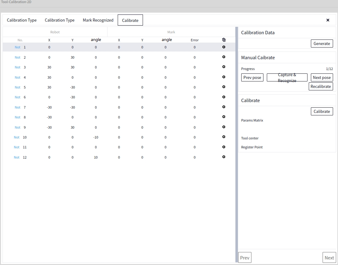
Photo Recognition#
The robot should move according to the generated poses in each line. After moving to the specified position, click Photo Recognition to check the Marker results in the data column
-Previous Pose: Mouse cursor focuses on the previous line of the current line -Next Pose: Mouse cursor focuses on the next line of the current line -Recalibrate: Restart calibration from the first line
Tip
After completing Photo Recognition for the current line, you need to click Next Pose and then click Photo Recognition again
View Data#
Click on the arrow in the image below to view the data of the current line
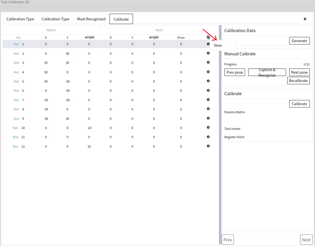
Calibration Calculation#
After all the data in the data column has been recognized, click the Calibration Calculation button
Save#
After successful calibration calculation, click Next to enter the Save interface. Click the arrow in the image below to select the file name and path to save, then click Save File
Automatic Calibration#
In the Calibration Mode interface, select Automatic Calibration and click Next to go to the Calibration Type settings. Set according to the actual situation, as shown below
After setting the Calibration Type, click Next to display the following interface
- In the above image
- Image Data:
Camera Data: Select the 2D image data of the locally connected camera
- Template Matching:
Template: Select a file saved using the 2D Template Creation tool from the local storage, the file format being xxx.dmtemp
Tip
Clicking Create Template here will directly jump to the 2D Template Creation interface
After selecting the template file, you can set the parameters under Marker Recognition Configuration, as shown below
Recognize and Set as Registration Point#
Same as Recognize and Set as Registration Point in Manual Calibration
Generate Poses#
Based on the above image, click Next to display the following interface
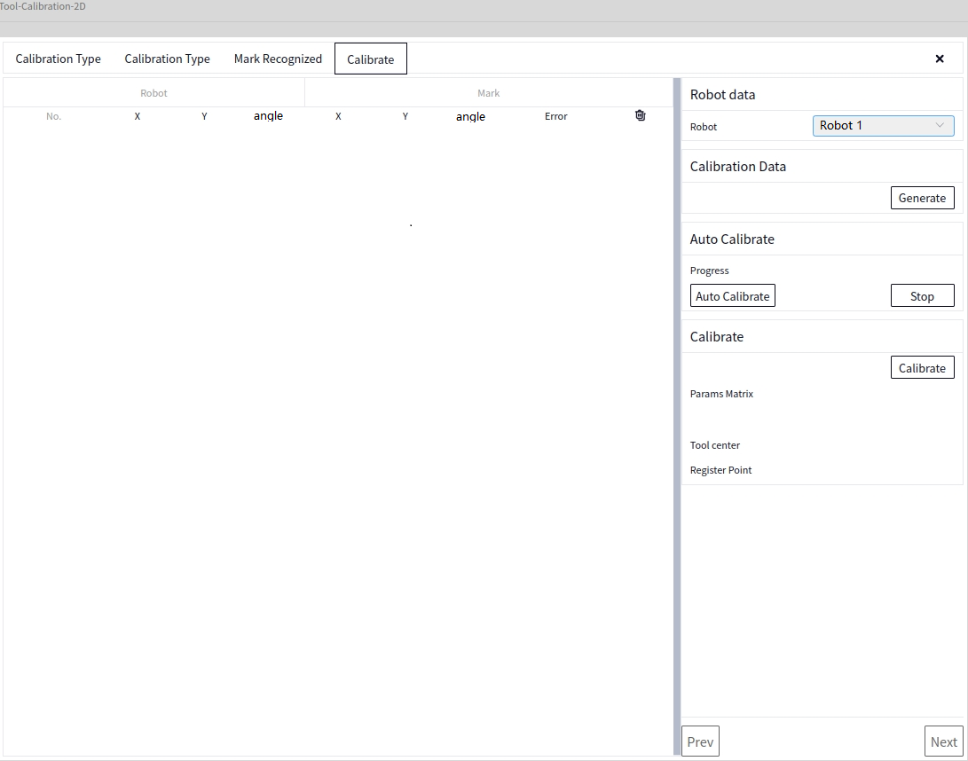
In the above image, you need to select the connected robot in Robot Pose before you can click Generate Poses. The Generate Poses method is the same as in Manual Calibration
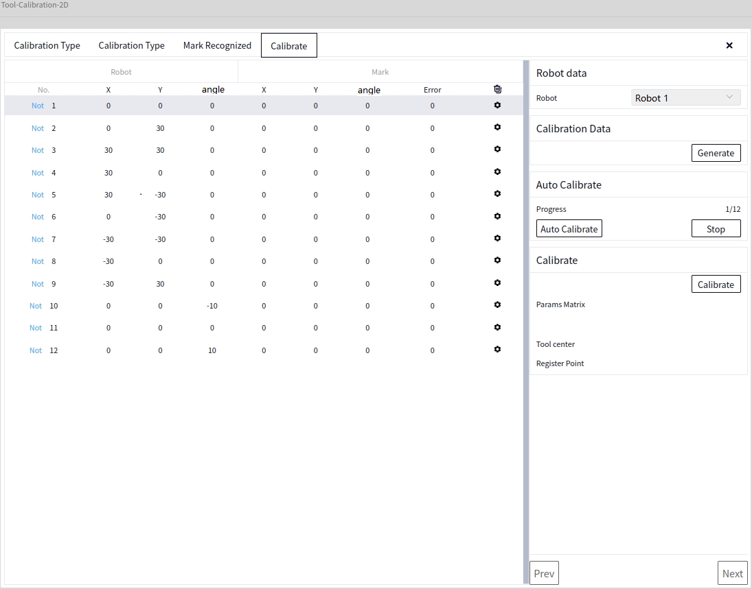
Automatic Calibration#
After generating the poses, click Automatic Calibration to start automatic calibration. You can click Stop Calibration to stop the ongoing calibration
Calibration Calculation#
After all the data in the data column has been recognized, click the Calibration Calculation button
Save#
After successful calibration calculation, click Next to enter the Save interface. Click the arrow in the image below to select the file name and path to save, then click Save File
Re-registration#
This mode allows re-setting registration points and recalculating calibration by reading the previously saved template file using the 12-Point Calibration tool.
In the Calibration Mode interface, select Re-registration and click Next to go to the Load Template interface. The template loaded at this time is the template file saved by previous Manual or Automatic calibration
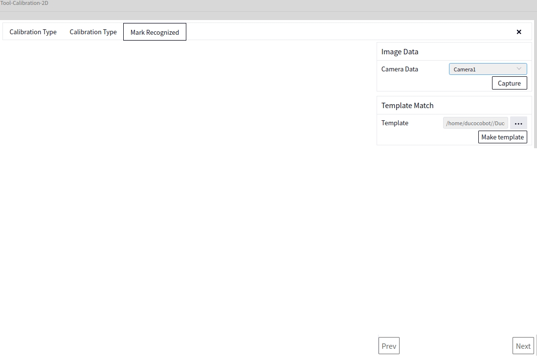
After setting the Template, click Next to display the following interface
- In the above image
- Image Data:
Camera Data: Select the 2D image data of the locally connected camera
- Template Matching:
Template: Select a file saved using the 2D Template Creation tool from the local storage, the file format being xxx.dmtemp
Tip
Clicking Create Template here will directly jump to the 2D Template Creation interface
After selecting the template file, you can set the parameters under Marker Recognition Configuration, as shown below
Recognize and Set as Registration Point#
Same as Recognize and Set as Registration Point in Manual Calibration
Calibration Calculation#
After all the data in the data column has been recognized, click the Calibration Calculation button
Save#
After successful calibration calculation, click Next to enter the Save interface. Click the arrow in the image below to select the file name and path to save, then click Save File
Dimmer Tool#
Entry#
Open the camera configuration after creating a new camera, click on Camera Parameters -> Dimmer Tool as shown below:
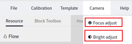
Tip
For details on how to create a new camera, refer to the content in New Camera
Enter the focus adjustment interface, select the camera, image, and click on continuous shooting in sequence as shown below:
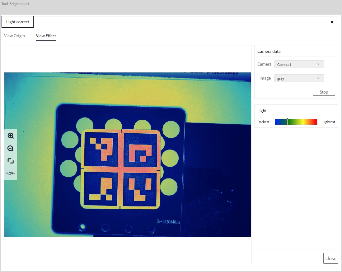
Observe the brightness indicator bar and image display. Adjust the camera as needed. Generally, it is considered that the image indicator bar being in the middle position indicates balanced image brightness.
Focusing Tool#
Entry#
Open the camera configuration after creating a new camera, and click Camera Parameters->Focusing Tool as shown below:
Tip
For detailed instructions on how to create a new camera, refer to Creating a New Camera.
Enter the focus adjustment interface, select the camera and image in sequence, and click Continuous Shooting as shown below:
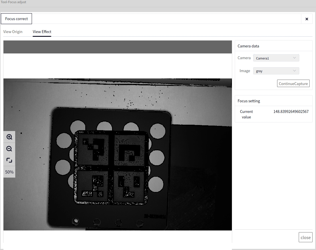
Adjust the camera and observe the Focus Settings->Current Value and Image Display. If you notice that the current value reaches a high level and the image edges appear sharp and clear, the focusing is complete.
System Management#
When logging into the software interface for the first time, click System Administrator at the top right of the interface to display the following screen
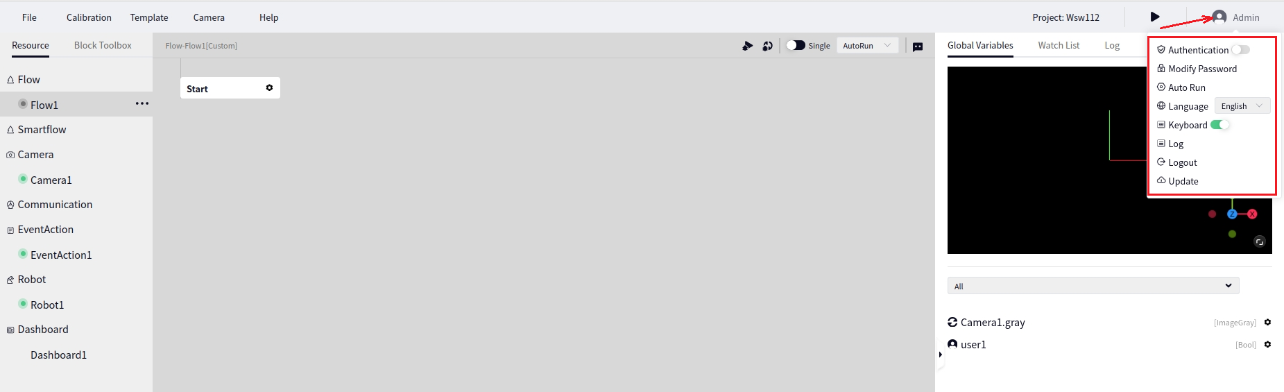
Login Authentication#
As shown in the above image, when the login authentication button is toggled left, the feature is disabled (default is disabled), and toggling the button to the right enables login authentication. After enabling, refresh the webpage to be redirected to the login screen which requires a username and password, as shown below:
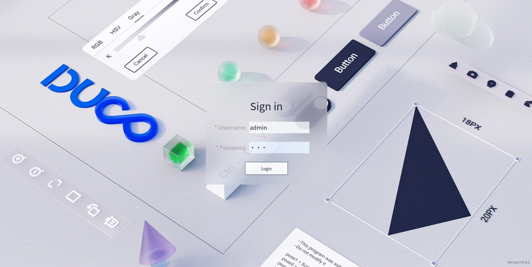
At this point, click the login button to proceed. Once logged in successfully, refreshing the webpage won’t redirect to the login screen again.
Tip
The default account and password are Account: admin, Password: 123
Change Password#
Click System Administrator->Change Password at the top right of the interface to bring up the following change password screen:
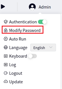
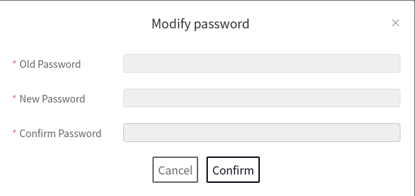
Auto-Start Settings#
Click System Administrator->Auto-Start Settings at the top right of the interface to bring up the following auto-start settings screen:
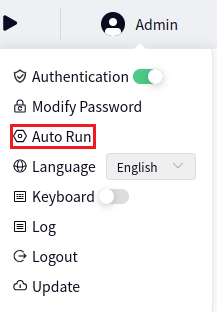
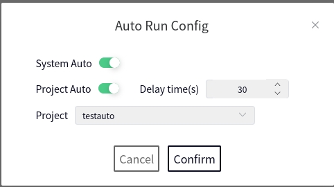
The System Auto-Start button defaults to off with the button toggled to the left. Toggling the button to the right enables System Auto-Start, which starts the system automatically upon booting, as shown below:
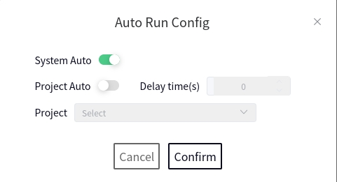
In the above image, Project Auto-Start is off. Toggling the button to the right enables Project Auto-Start, allowing you to set the delay for project auto-start and specify which project to start.
Language#
Click System Administrator->Language at the top right of the interface to bring up the following language settings screen:
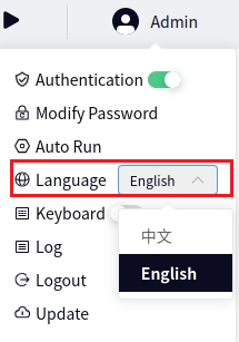
In the above image, you can switch between Chinese and English and set changes to take effect immediately.
Logs#
Click System Administrator->Logs at the top right of the interface to bring up the following log retention settings screen:
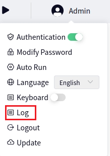
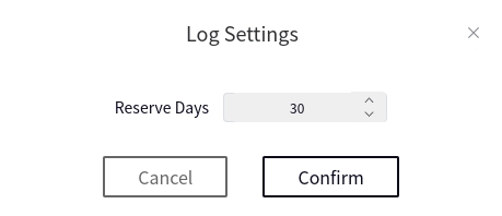
The default log retention period is 30 days. Modify the retention period and click OK to save changes.
Logout#
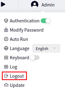
Click System Administrator->Logout at the top right of the interface to log out the current user.
Update#
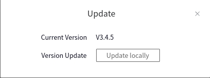
Click System Administrator->Update at the top right of the interface to bring up the update pop-up window:
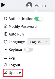
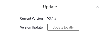
Click Local Update in the image above to open the file browser, then select the latest deb package.
About#
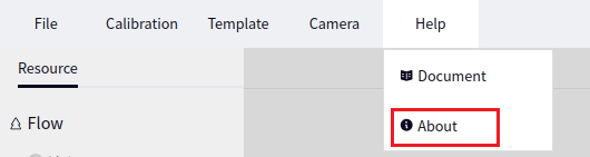
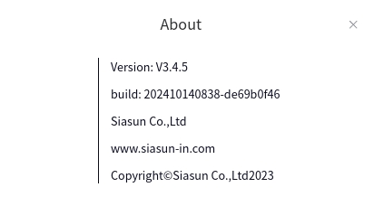
Click System Administrator->About at the top right of the interface to display the about window:
Engineering Operation#
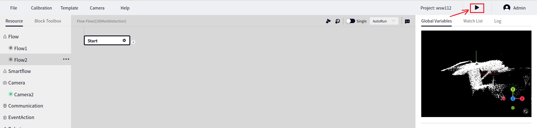
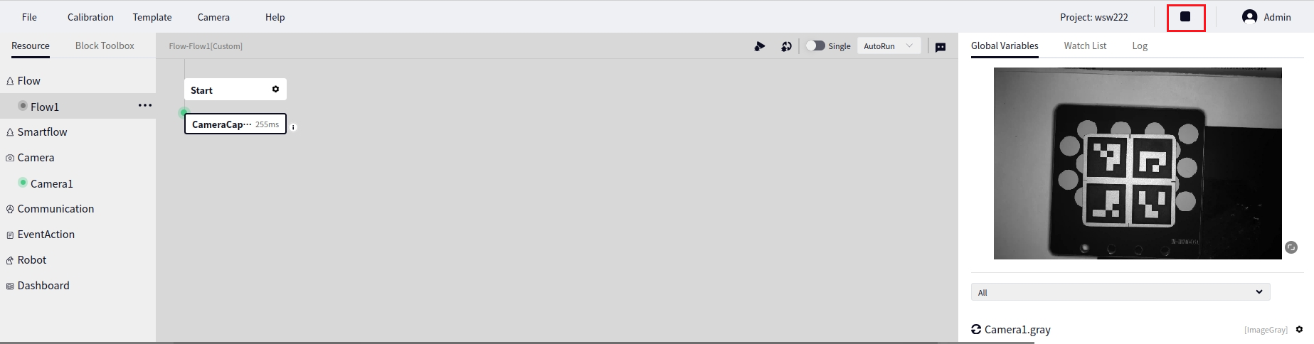
To open a project, click the arrow indicated in the image below to run the entire project.
Tip
When the project is running, the button to run the entire process and buttons such as camera capture are disabled. Click the button shown above again to stop the entire project from running.
A process will only be executed if the Run Mode in the Flow is set to non-Trigger Mode. If the flow is set to Trigger Mode, clicking the Project Run button will not run the process, and an error popup will appear as shown below.
Tip
When the flow is configured to run in a Loop mode, clicking the project run will cause the process to run continuously; otherwise, it will run only once.
Software Package Update#
The DUCO Mind application package is a deb package. The update process is essentially the installation of a new deb package. There are two ways to update: through the Duco Management Center software or directly through the DUCO Mind application.
Tip
The update package should be placed in a USB drive and inserted into the controller before performing the update.
Updating through the Duco Management Center#
Open the Duco Management Center software and click the Update button on the left. The result is shown in the following image:
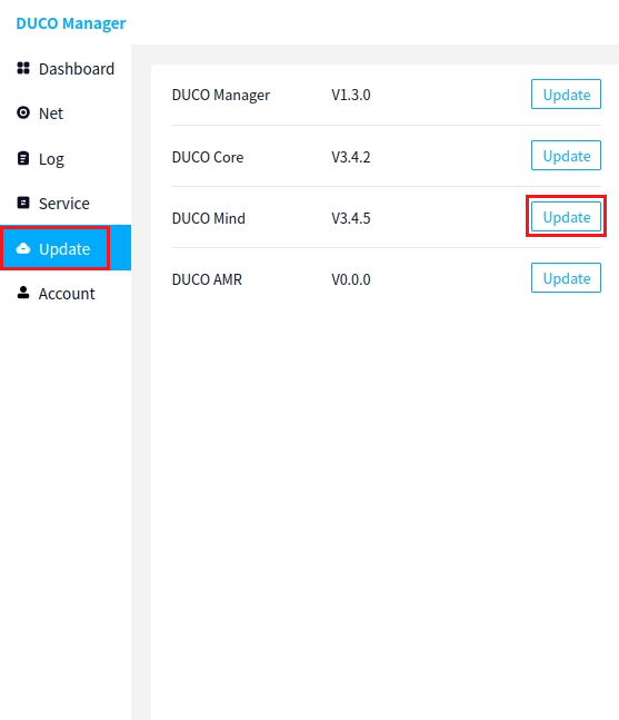
Click the Local Update button next to DUCO Mind as indicated by the arrow in the image above to bring up the interface shown below:
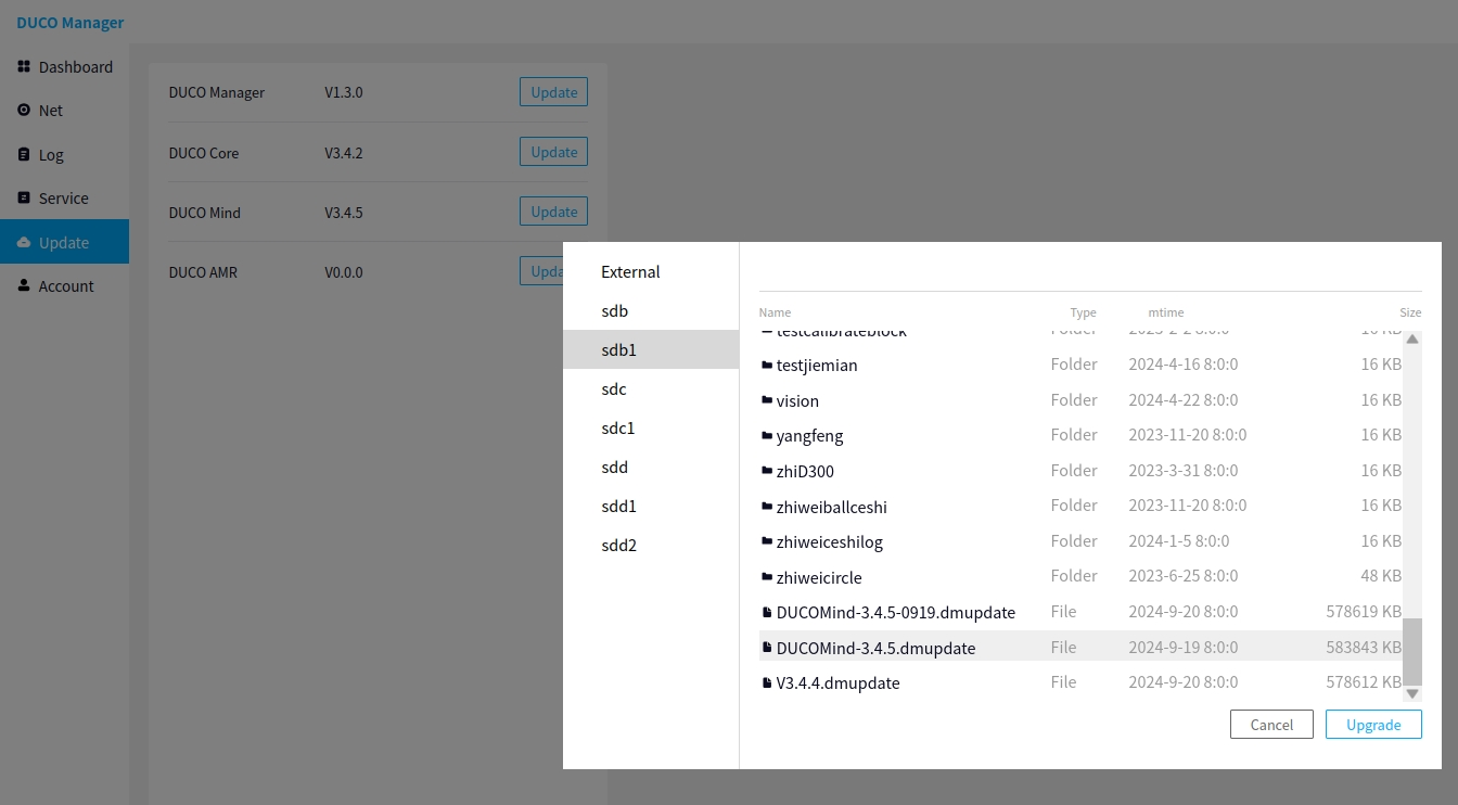
In the image above, select the name of the update package you need and click the Update button. When the following prompt appears, it indicates that the update preparation is complete, and the application needs to be restarted:
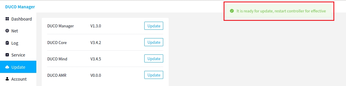
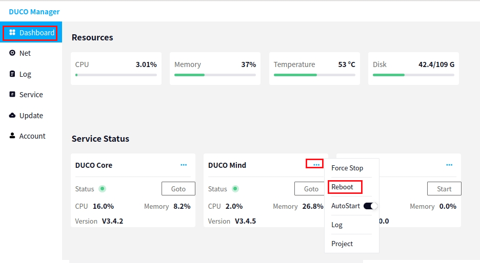
At this point, click the Status Monitoring button on the left, then click the button at the top right corner of the DUCO Mind application and select Restart, as shown below:
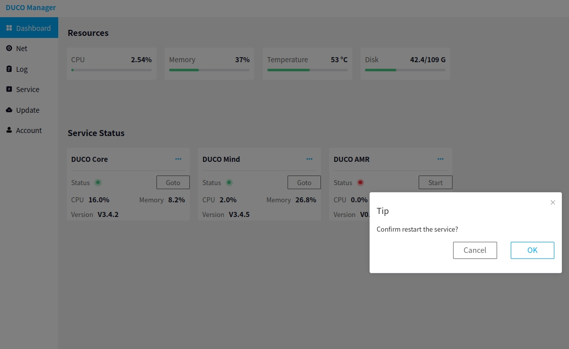
After clicking the Restart button, the following prompt box will appear. Click OK.
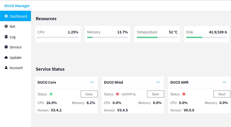
After clicking OK, the status of the DUCO Mind application on the interface will show Updating, indicating that the update operation was successful. Wait for the application to finish updating, as shown below:
Updating through DucoMind#
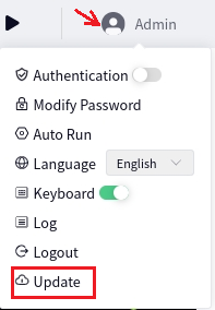
Click the system administrator (current user) in the top right corner of the DUCO Mind interface. In the popup box that appears, click the Update button, as shown below:
After clicking Update, the following interface will appear. The current version of DUCO Mind will be displayed. At this point, click the Local Update button to display the files on the USB drive mounted on the controller. Select the software package you want to update and click Update.