


Operator Usage Instructions#
2D Vision Operators#
IO#
Read Image#
Introduction#
Image reading is used to read images from the local path.
Input#
- Input Path
Type:
StringMeaning: File path
Output#
- Read Image
Type:
ImageColorImageGrayMeaning: Outputs an image to the global variable list
Parameters#
- File Input Type
Meaning: Source of the file path
Range:
Set by parameter: Set the file path via configuration parameter ‘File Path’
Set by input variable: Set the file path via input variable ‘Input Path’
- File Path
Meaning: Choose the image reading path
- Image Type
Range: Color Image, Grayscale Image
Tip
The type of image variable changes according to the configuration parameters.
Save Image#
Introduction#
Image saving is used to save images processed in the software to local storage or a USB drive.
Input#
- Input Image
Type:
ImageColorImageGrayMeaning: An image from the global variable list
Parameters#
- File Save Type
Meaning: Source of the file path
Range:
Set by parameter: Set the file path via configuration parameter ‘File Path’
Set by input variable: Set the file path via input variable ‘Input Path’
- Save Path
Meaning: Choose the image saving path
- Save Type
Range:
pngjpgbmp
- Suffix
Range: None, Timestamp, Counter
Save Image Ftp#
Introduction#
Image saving is used to save images processed in the software to FTP.
Input#
- Input Image
Type:
ImageColorImageGrayMeaning: An image from the global variable list
Parameters#
FTP Server Settings
- FTP Server Address
- Meaning: FTP server address
Range: Default 127.0.0.1
- FTP Server Port
- Meaning: FTP server network port
Range: Default 21
- Username
Meaning: FTP server username
- Password
Meaning: FTP server password
- OverTime (ms)
Meaning: Maximum connection time to the FTP server, connection stops if exceeded
File Saving Settings
- File Save Type
Meaning: Source of the image saving path
Range:
Set by parameter: Set the image path via configuration parameter ‘Save Path’
Set by input variable: Set the image path via input variable ‘Input Path’
- Save Path
Meaning: Choose the path under the created FTP site where the image will be saved
- Save Type
Range:
pngjpgbmp
- Suffix
Range: None, Timestamp, Counter
1 Setting Up an FTP Server
This manual is for Windows 10 Professional.
1.1 Install IIS Web Server
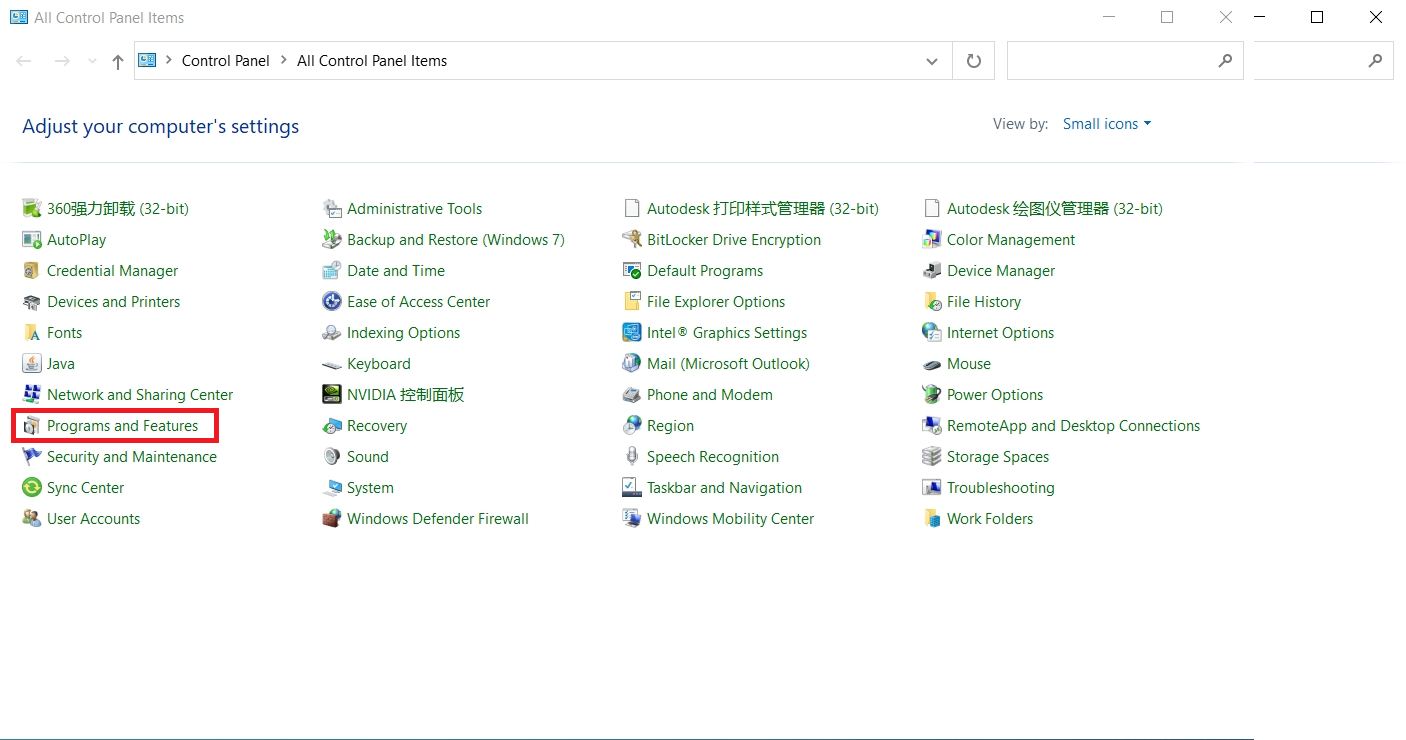
1.1.1 In the Control Panel, find Programs and Features and open it.
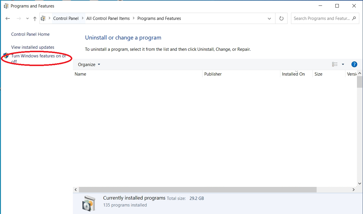
1.1.2 Click Turn Windows features on or off in the Programs and Features interface.
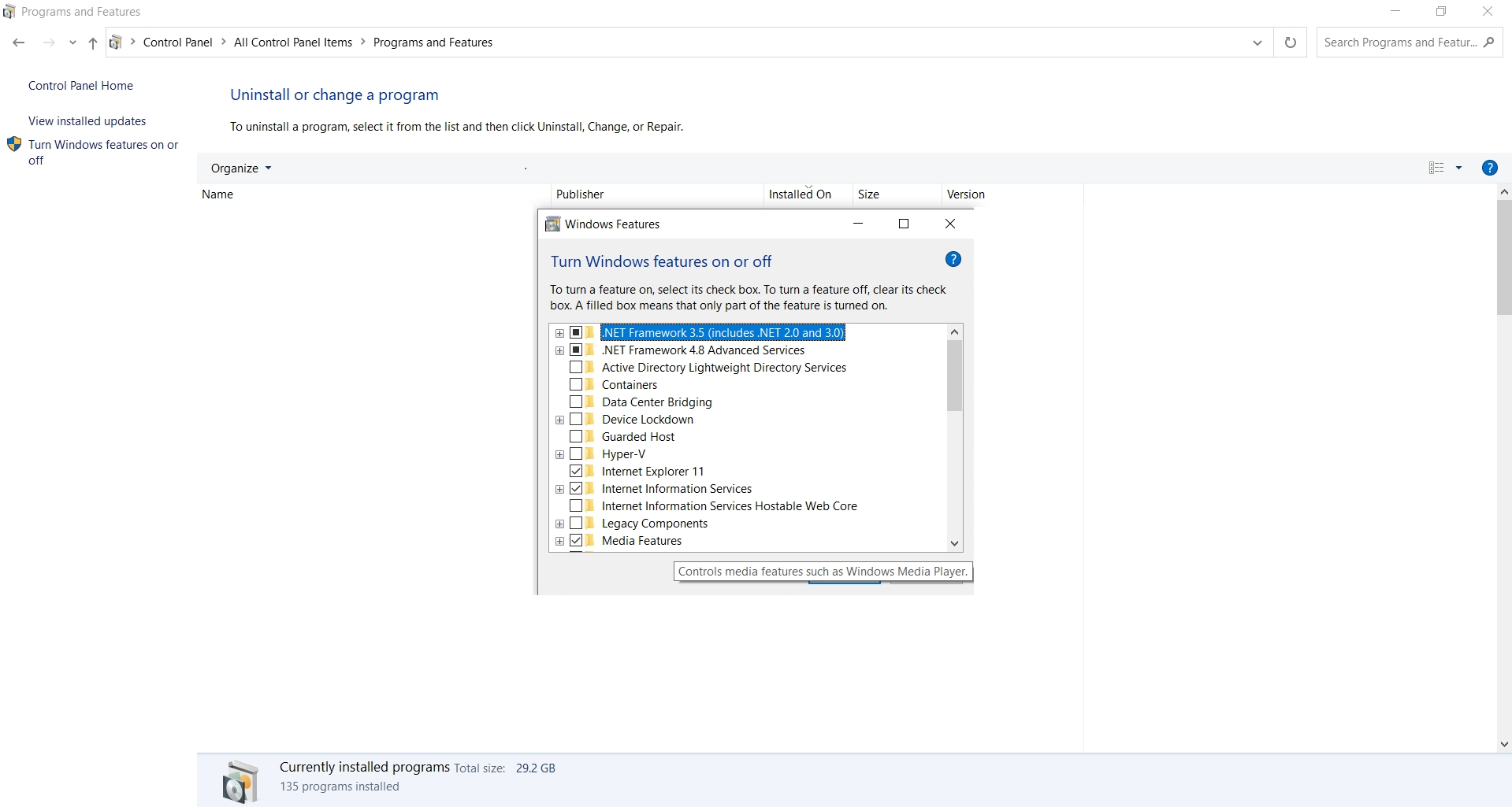
1.1.3 In the Windows Features popup, find and open Internet Information Services.
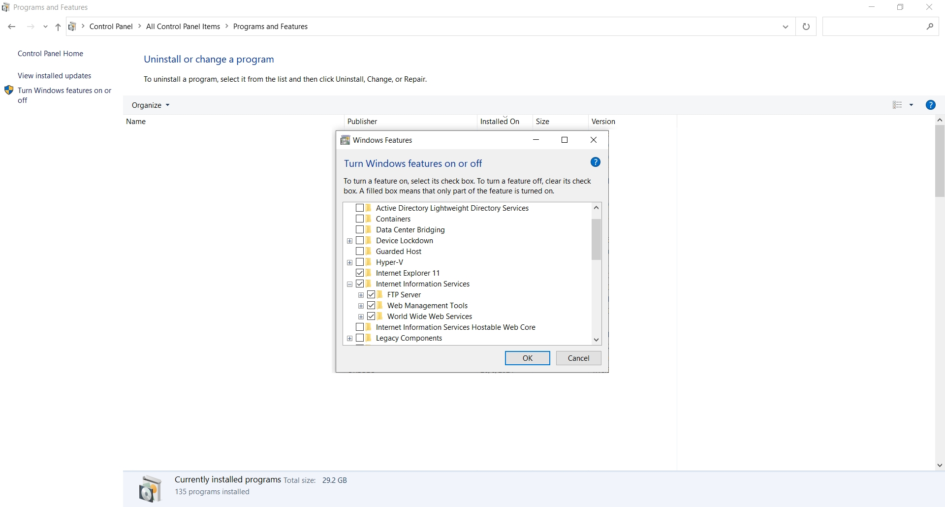
1.1.4 Select FTP Server, Web Management Tools, and World Wide Web Services under Internet Information Services. Click OK after selecting.
Note
Make sure all checkboxes are selected with check marks. If it’s a black box, it means some sub-items are not selected.
1.2 Set FTP Service to Start Automatically on Boot
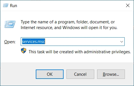
1.2.1 Press win + R to open the run window, enter services.msc and click OK.
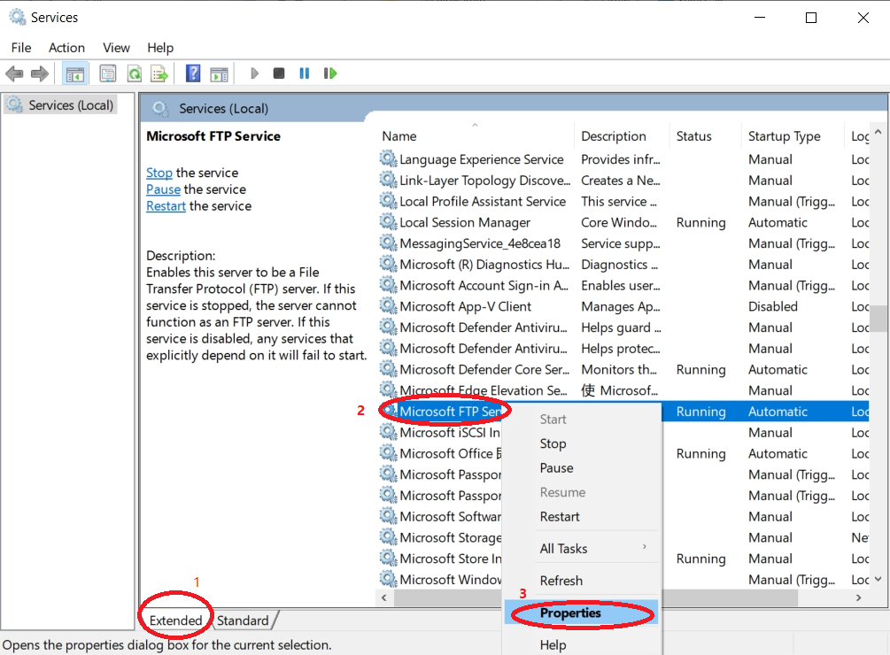
1.2.2 Click Extended, find Microsoft FTP Service, right-click and select Properties.
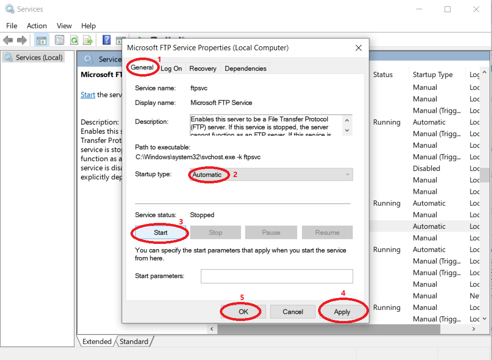
1.2.3 In the properties popup, click General, select Automatic for the startup type, Start for the service status, then click Apply->OK.
Tip
Even if you set up the FTP server to start on boot, it sometimes does not start automatically after restarting the computer and needs to be started manually.
1.3 Configure the FTP Server
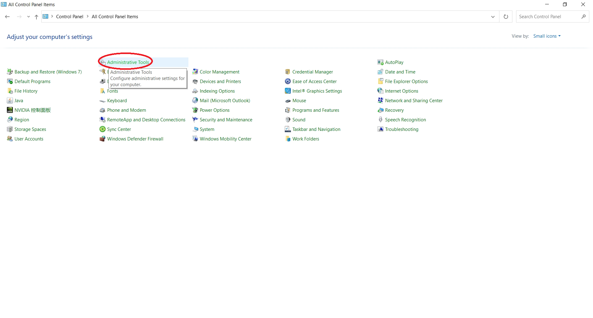
1.3.1 In the Control Panel, find Administrative Tools and open it.
1.3.2 Find Internet Information Services (IIS) Manager, right-click and select Send to -> Desktop (create shortcut).
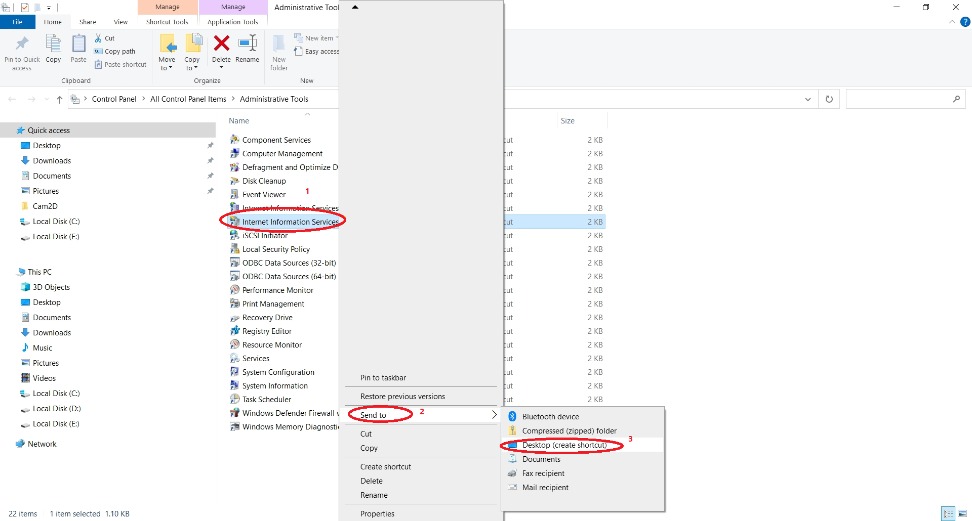
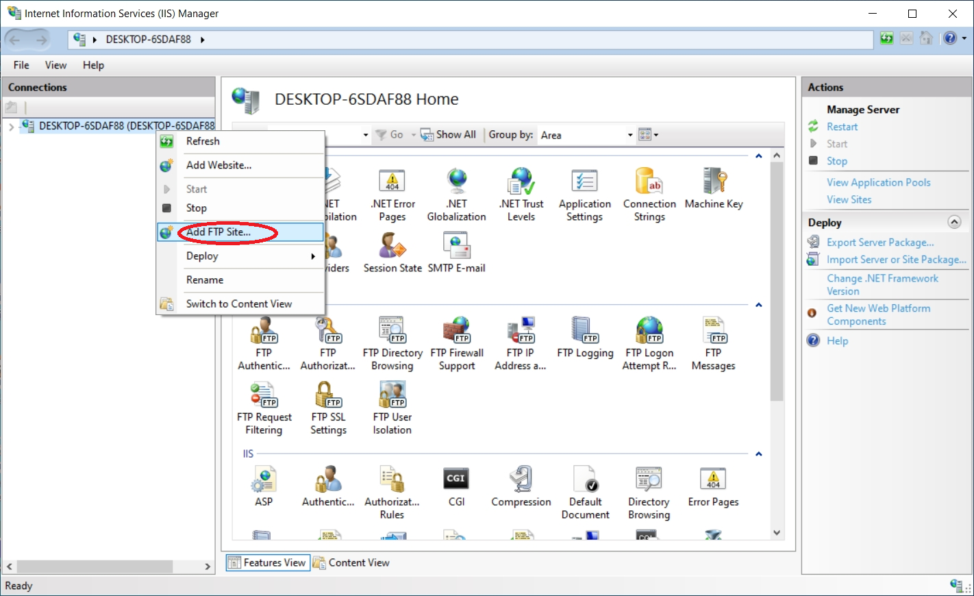
1.3.3 Click the desktop icon Internet Information Services (IIS) Manager, right-click Sites on the left sidebar, and select Add FTP Site.
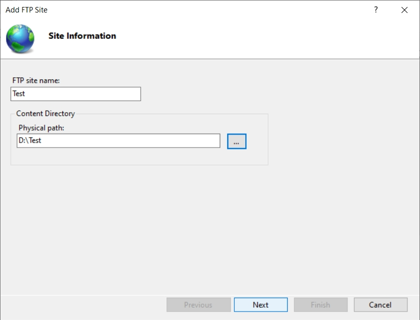
1.3.4 Customize FTP Site Name and Physical Path, then click Next.
1.3.5 View your IP address. Open command prompt, type ipconfig, and copy the IPv4 address.
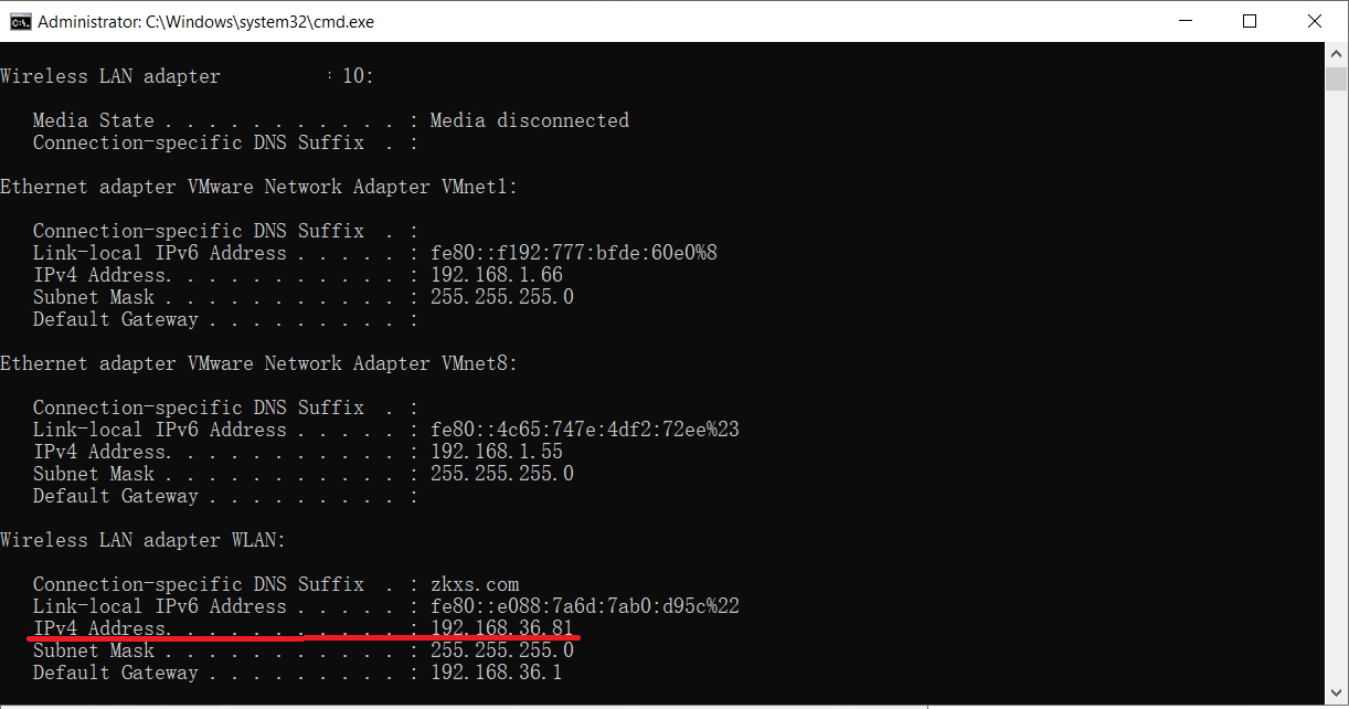
1.3.6 Paste the copied address into the IP Address of the new FTP site and select the port. Also, click No SSL -> Next.
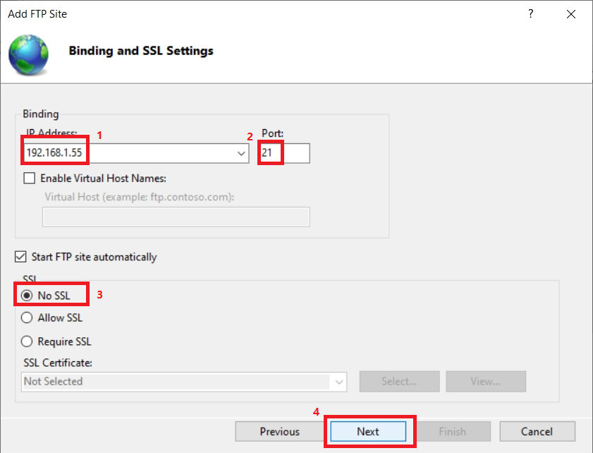
1.3.7 Select Anonymous and Basic for authentication, choose All Users for access, and select Read and Write permissions. Finally, click Finish.
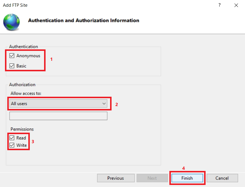
1.4 Allow FTP Server through Windows Firewall
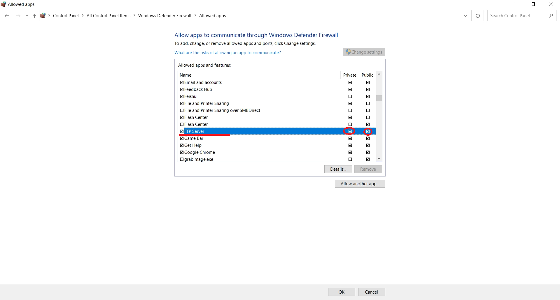
1.4.1 In the Control Panel, click Windows Defender Firewall.
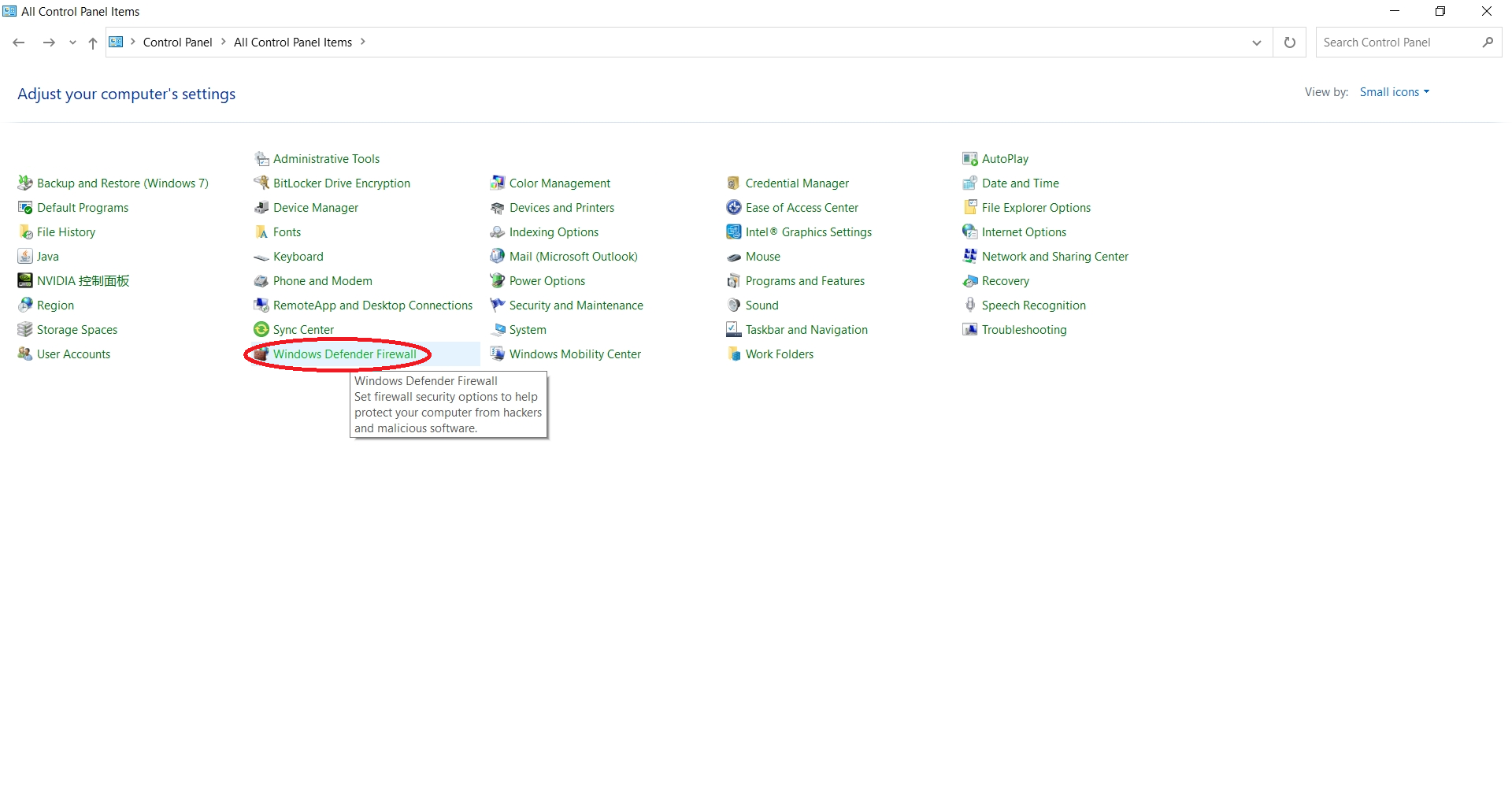
1.4.2 Select Allow an app or feature through Windows Defender Firewall.
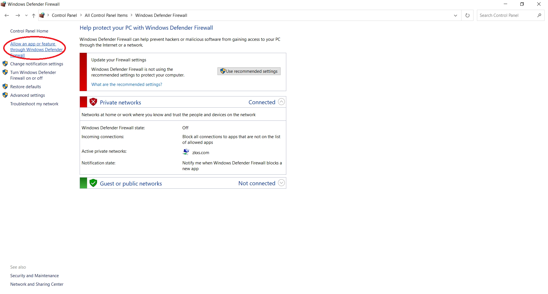
1.4.3 Find FTP Server and select both Private and Public.
2 Specific User Access
On the basis of successfully setting up the FTP server, set the username and password to achieve user access control and differentiate FTP server users.
Tip
If all users can access the FTP server, steps after 1.3 are not required.
2.1 Creating an FTP User
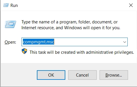
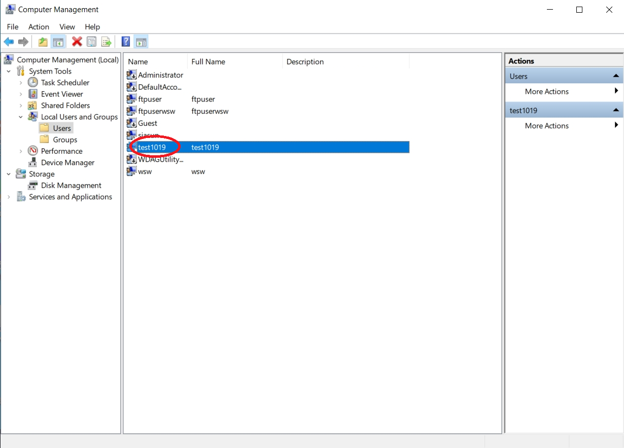
2.1.1 Press win + R to open the run window, enter compmgmt.msc and click OK.
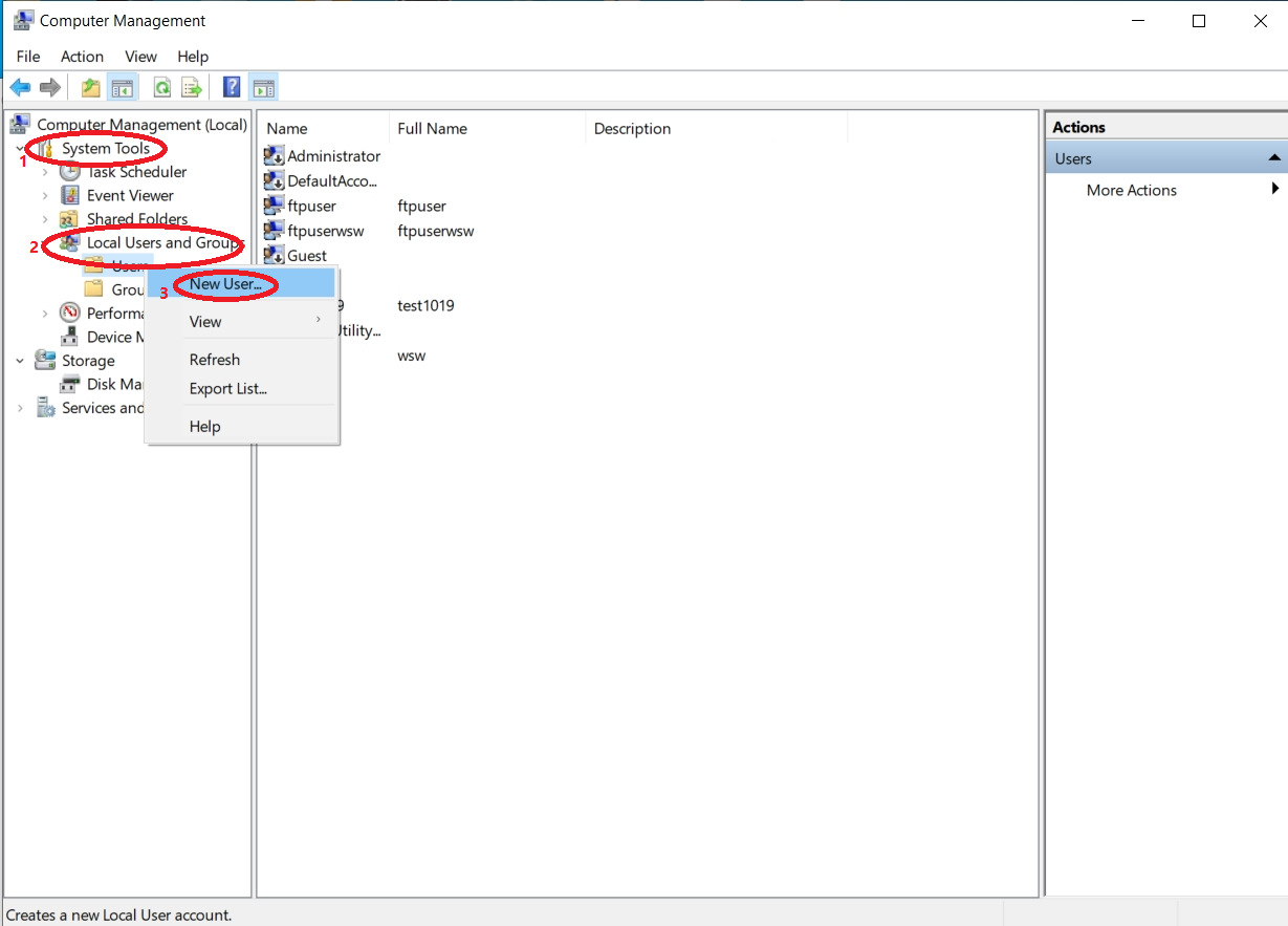
2.1.2 Click System Tools -> Local Users and Groups, right-click Users, and select New User.
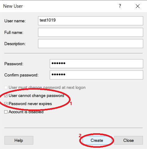
2.1.3 Fill in User Name, Password, and Confirm Password, select User cannot change password and Password never expires. Click Create when finished.
Note
This account is essentially a computer account. Hence, you can use your login credentials for the computer to log into the FTP site without creating a test account. The ‘User Name’ and ‘Full Name’ need to be consistent, and the password is optional.
2.2 Setting a Specific User
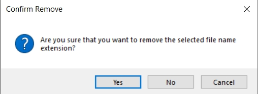
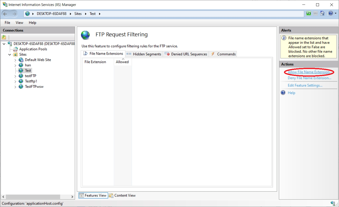
2.2.1 Click FTP Authorization Rules and delete all users.
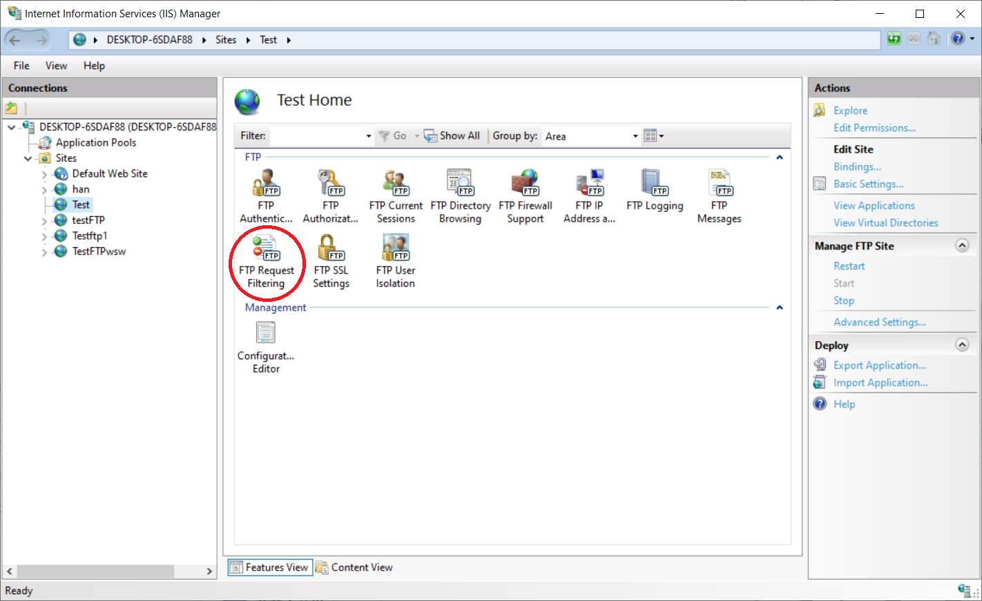
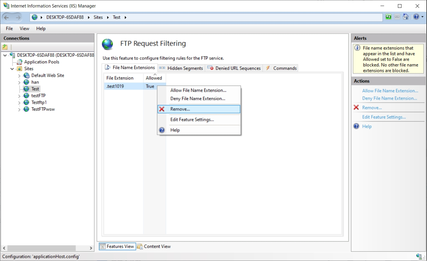
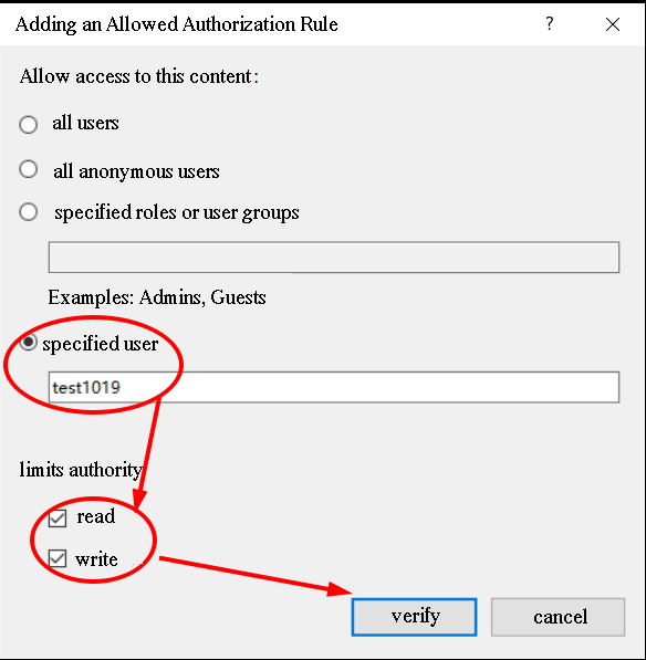
2.2.2 Add an allow authorization rule, select the specific user, fill in the added username, and select user permissions (Read/Write). Click OK when done.
2.3 FTP Verification Test
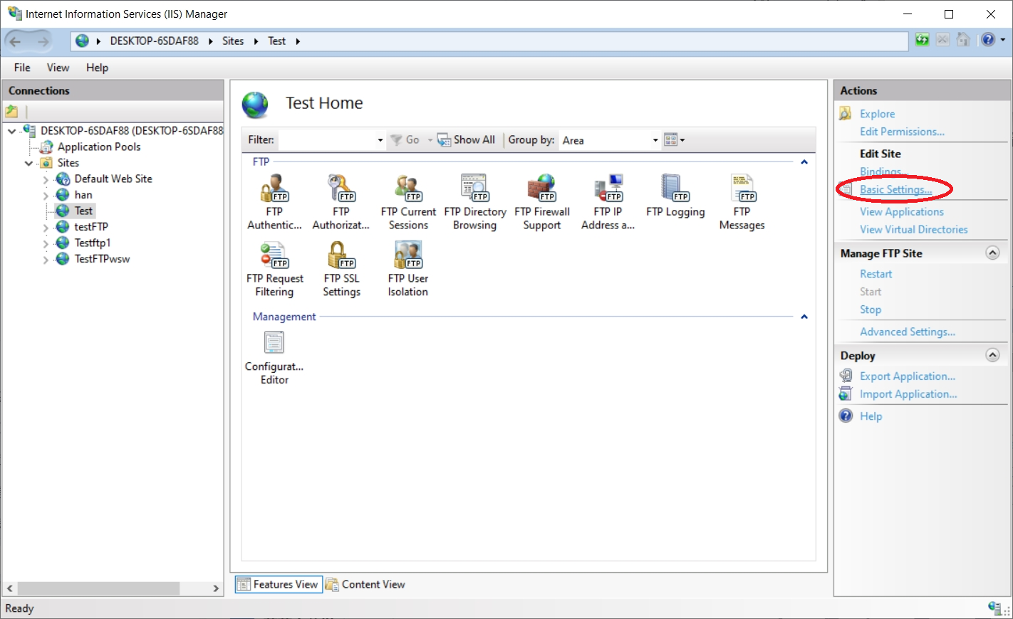
2.3.1 Click Actions -> Edit Site -> Basic Settings on the right sidebar.
2.3.2 Click Test Settings.
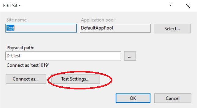
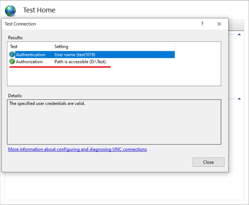
2.3.3 If Test Results show Authorization: Cannot verify access to path, proceed to step 3.4 and click Close. Otherwise, the verification test is complete.
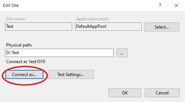
2.3.4 Click Connect as.
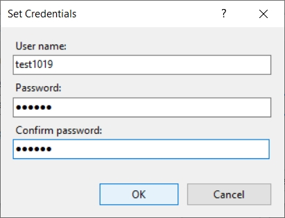
2.3.5 Set credentials: Log in with the created username and password, click OK. Go back to Test Settings, now Test Results should show Authorization: Path can be accessed.
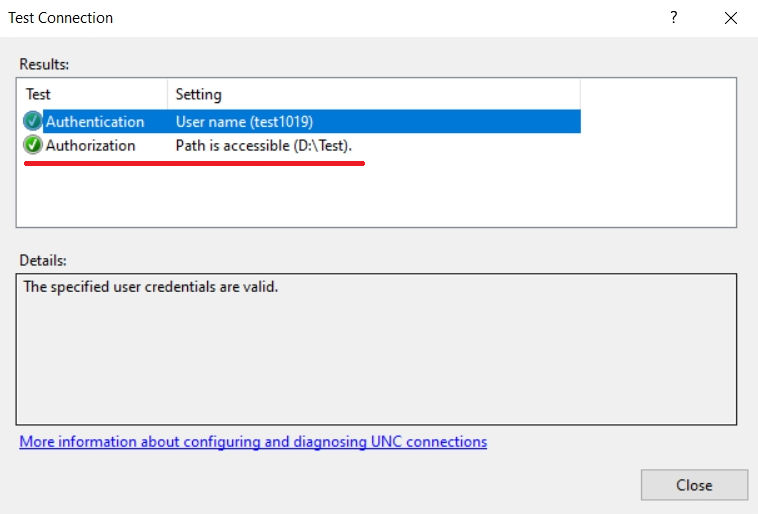
3 File Upload and Download
3.1 File Download
3.1.1 Enter the FTP address in the browser or file manager address bar, enter the created (or existing) username and password to access the specific user.
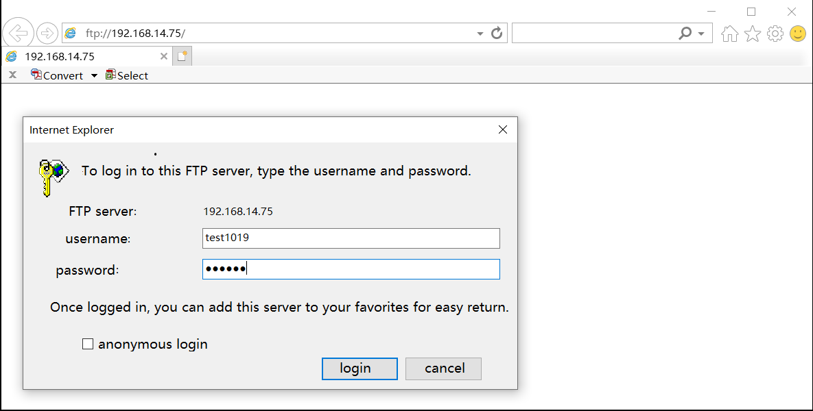
3.1.2 After a successful login, click the respective file to download it.
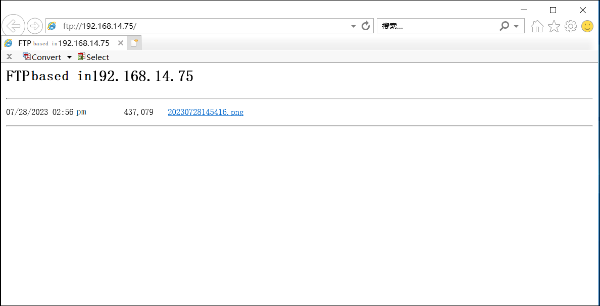
3.2 File Upload
3.2.1 In the file explorer, enter ftp://your ip address:port number or choose the corresponding physical path for FTP.
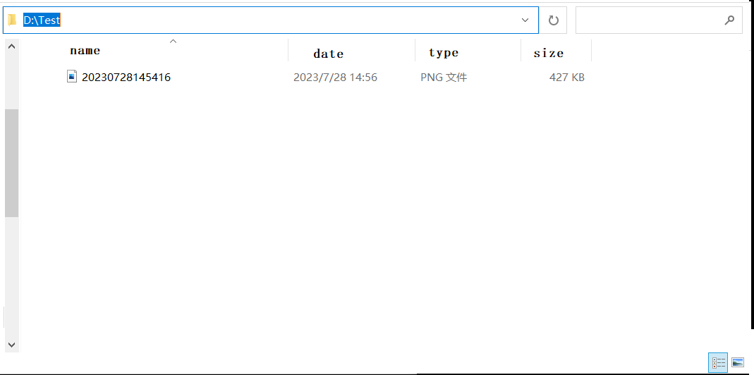
3.2.2 Enter the respective username and password, then drag and drop or create files to upload them.
Note
This completes the setup of the FTP server, allowing others within the same local network to not only access your computer but also transfer files between them.
Preprocessing#
Filter2D#
Introduction#
Perform filtering preprocessing on the image to make it easier to analyze features.
Input#
- Input Image
Type:
ImageColorImageGrayMeaning: Image to be processed
Output#
- Output Image
Type:
ImageColorImageGrayMeaning: Resulting image
Function#
Parameters#
- Filter Method
Meaning: Choose a filtering method
Range: Box Filter, Mean Filter, Gaussian Filter, Median Filter, Bilateral Filter, Ideal Low-Pass Filter, Ideal High-Pass Filter, Gaussian Low-Pass Filter, Gaussian High-Pass Filter, Butterworth Low-Pass Filter, Butterworth High-Pass Filter
- Box Blur - Filter Kernel Radius
Meaning: The larger the kernel, the more pronounced the effect
Range: 3 * 3, 5 * 5, 7 * 7, 9 * 9, 11 * 11, 13 * 13, 15 * 15, 17 * 17, 19 * 19, 21 * 21
- Mean Blur - Filter Kernel Radius
Meaning: The larger the kernel, the more pronounced the effect
Range: 3 * 3, 5 * 5, 7 * 7, 9 * 9, 11 * 11, 13 * 13, 15 * 15, 17 * 17, 19 * 19, 21 * 21
- Gaussian Blur - Filter Kernel Radius
Meaning: The larger the kernel, the more pronounced the effect
Range: 3 * 3, 5 * 5, 7 * 7, 9 * 9, 11 * 11, 13 * 13, 15 * 15, 17 * 17, 19 * 19, 21 * 21
- Median Blur - Filter Kernel Radius
Meaning: The larger the kernel, the more pronounced the effect
Range: 3 * 3, 5 * 5, 7 * 7, 9 * 9, 11 * 11, 13 * 13, 15 * 15, 17 * 17, 19 * 19, 21 * 21
- Bilateral Blur - Filter Kernel Radius
Meaning: The larger the kernel, the more pronounced the effect
Range: 3 * 3, 5 * 5, 7 * 7, 9 * 9, 11 * 11, 13 * 13, 15 * 15, 17 * 17, 19 * 19, 21 * 21
- Ideal Low-Pass Filter - Filter Kernel Radius
Meaning: The larger the kernel, the more pronounced the effect
Range: [0.1, 300]
- Ideal High-Pass Filter - Filter Kernel Radius
Meaning:
Range: [0.1, 300]
- Gaussian Low-Pass Filter - Filter Kernel Radius
Meaning:
Range: [0.1, 300]
- Gaussian High-Pass Filter - Filter Kernel Radius
Meaning:
Range: [0.1, 300]
- Butterworth Low-Pass Filter - Filter Kernel Radius
Meaning:
Range: [0.1, 300]
- Butterworth Low-Pass Filter - Order
Meaning:
Range: [1, 4]
- Butterworth High-Pass Filter - Filter Kernel Radius
Meaning:
Range: [0.1, 300]
- Butterworth Low-Pass Filter - Order
Meaning:
Range: [1, 4]
Examples#
Algorithm |
Example: Input Image |
Example: Output Image |
|---|---|---|
Box Blur |
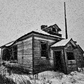
|
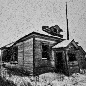
|
Mean Blur |
|
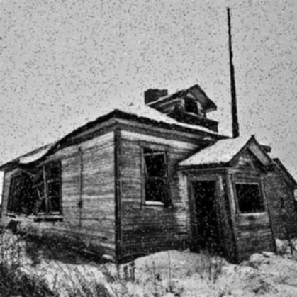
|
Gaussian Blur |
|
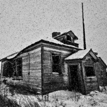
|
Median Blur |
|
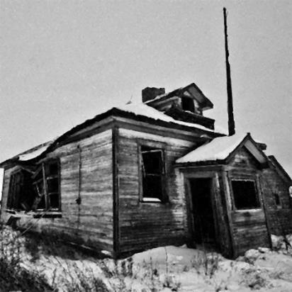
|
Bilateral Blur |
|
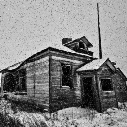
|
Ideal Low-Pass Filter |
|
|
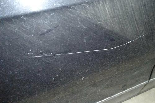
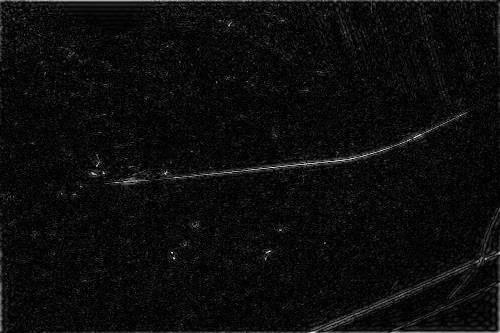
Ideal High-Pass Filter |
|
|
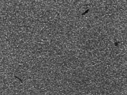
Gaussian Low-Pass Filter |
|
|
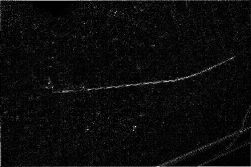
Gaussian High-Pass Filter |
|
|
Butterworth Low-Pass Filter |
|
|
Butterworth High-Pass Filter |
|
|
Image Enhance#
Introduction#
Perform enhancement preprocessing on the image to make it easier to analyze features.
Input#
- Input Image
Type:
ImageColorImageGrayMeaning: Image to be processed
Output#
- Output Image
Type:
ImageColorImageGrayMeaning: Resulting image
Function#
Algorithm |
Function |
|---|---|
Image Resize |
Scale the image proportionally |
Histogram Equalization |
Adjust the global contrast of the image by equalizing its histogram. Increases contrast especially in cases where useful data is represented by similar values. This method is very effective for improving contrast in both very dark and very bright areas. |
Gray Invert |
Invert the black and white values of the image |
Bright Change |
Brightness represents the dark and light aspects of the image, with higher gray values indicating a brighter image. Contrast is the degree of difference between colors, with higher contrast making differences more apparent. |
Gamma Correction |
Adjust image details using gamma correction |
Local Enhance |
By changing the enhancement ratio, the gray values in the image can achieve clearer distinction between black and white |
Mean Enhance |
Compared with local enhancement, uniform enhancement results in more uniform gray values with less distinct black-white boundaries |
Two Threshold Linearization |
Perform linear operations on image gray values based on minimum and maximum thresholds |
MultiImg |
Multiply each pixel intensity value by an enhancement ratio and add an offset value |
Pixel Manip |
Perform add, subtract, multiply, and divide operations on image pixel gray values |
Clip Gray |
Limit the gray range of input image to a certain range, setting values above the max threshold to max and below the min threshold to min |
Stretch Gray |
Perform linear coefficient changes on the gray values of the input image |
Range Gray |
Retain the original gray value of pixels within the minimum-maximum threshold range, and set others to 0 |
Parameters#
- Image Enhance Method
Meaning: Choose an image enhancement method
Range: Image Resize, Histogram Equalization, Gray Invert, Bright Change, Gamma Correction, Local Enhance, Mean Enhance, Two Threshold Linearization, MultiImg, Pixel Manip, Clip Gray, Stretch Gray, Range Gray
- Image Resize - Size Change Ratio:
Meaning: Ratio is proportional
Range: [0.1, 10]
- Bright Change - Scaling Factor:
Meaning:
Range: [0, 255]
- Bright Change - Scaling Value Offset:
Meaning:
Range: [0, 255]
- Gamma Correction - Gamma Correction Coefficient:
Meaning: The larger the Gamma value, the clearer the image details
Range: [0, 10]
- Local Enhance - Local Enhance Ratio:
Meaning: Ratio is proportional
Range: [0.1, 10]
- Mean Enhance - Mean Enhance Ratio:
Meaning: Ratio is proportional
Range: [0.1, 10]
- Two Threshold Linearization - Minimum Threshold:
Meaning: Minimum threshold
Range: [0, 255]
- Two Threshold Linearization - Maximum Threshold:
Meaning: Maximum threshold
Range: [0, 255]
- MultiImg - Enhancement Ratio:
Meaning: Value to multiply each pixel by
Range: [0.001, 200]
- MultiImg - Offset Value:
Meaning: Value to add to each pixel
Range: [-255, 255]
- Pixel Manip - Pixel Operation Method:
Meaning: Method for pixel operations
Range: Addition, Subtraction, Multiplication, Division
- Pixel Manip - Gray Value:
Meaning: Right-hand value for pixel operation
Range: [1, 255]
- Clip Gray - Minimum Threshold:
Meaning: Minimum threshold
Range: [0, 255]
- Clip Gray - Maximum Threshold:
Meaning: Maximum threshold
Range: [0, 255]
- Stretch Gray - Minimum Threshold:
Meaning: Minimum threshold
Range: [0, 255]
- Stretch Gray - Maximum Threshold:
Meaning: Maximum threshold
Range: [0, 255]
- Range Gray - Minimum Threshold:
Meaning: Minimum threshold
Range: [0, 255]
- Range Gray - Maximum Threshold:
Meaning: Maximum threshold
Range: [0, 255]
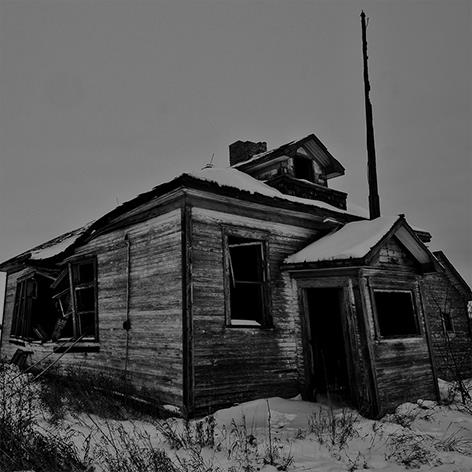
Examples#
Algorithm |
Example: Input Image |
Example: Output Image |
|---|---|---|
Image ReSize |
|
|
Histogram Equalization |
|
|
Gray Invert |
|
|
Bright Change |
|
|
Gamma Correction |
|
|
Local Enhance |
|
|
Mean Enhance |
|
|
Two Threshold Linearization |
|
|
MultiImg |
|
|
Pixel Manip - Addition |
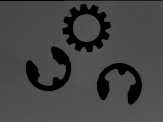
|
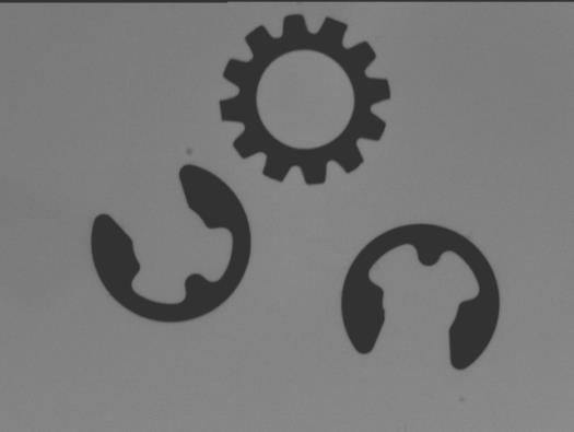
|
Pixel Manip - Subtraction |
|
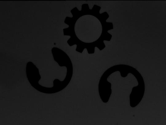
|
Pixel Manip - Multiplication |
|
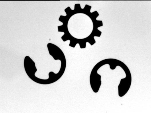
|
Pixel Manip - Division |
|
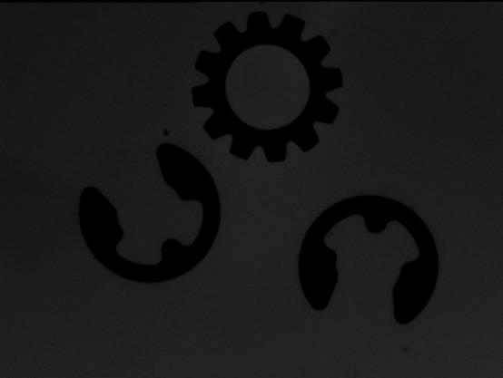
|
Clip Gray |
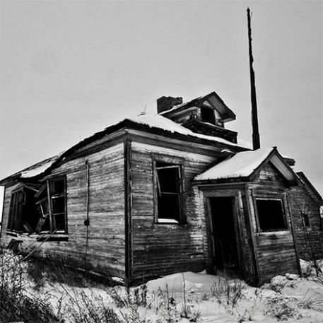
|
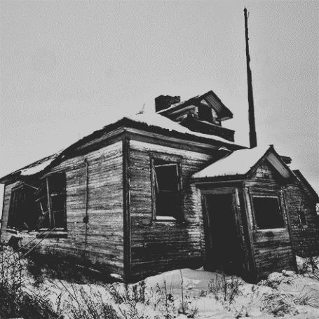
|
Stretchi Gray |
|
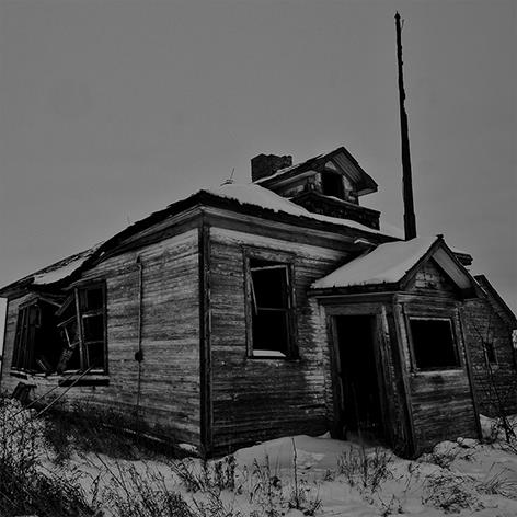
|
Range Gray |
|
|
BGR2Gray#
Introduction#
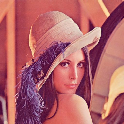
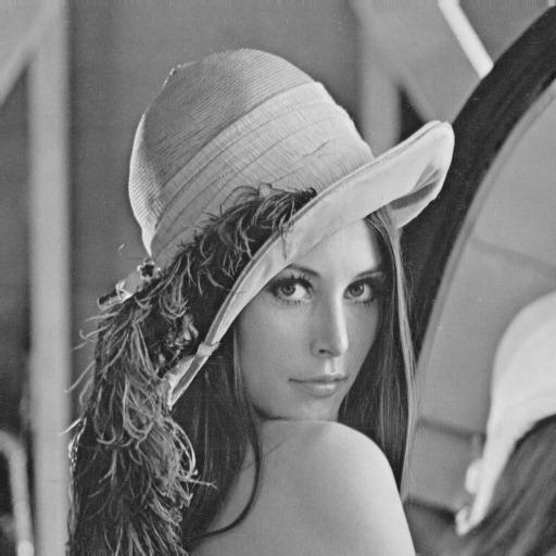
Convert a color RGB image to a single-channel grayscale image
Input#
- Input Image
Type:
ImageColorMeaning: Input color image to be processed
Output#
- Output Image
Type:
ImageGrayMeaning: Resulting grayscale image
Examples#
Input Image
Output Image
Edge Detection#
Introduction#
Apply edge detection preprocessing to the image to make its features easier to analyze.
Input#
- Input Image
Type:
ImageColorImageGrayMeaning: The image to be processed
Output#
- Output Image
Type:
ImageColorImageGrayMeaning: The result image
Function#
Algorithm |
Function |
|---|---|
Canny |
The Canny operator is currently one of the most theoretically complete edge detection algorithms. It is widely used. |
Sobel |
The Sobel operator detects edges by calculating the weighted difference of pixel intensities between neighboring pixels in the vertical and horizontal directions. It offers noise smoothing and provides relatively accurate edge direction information. Edge detection highlights the image’s contours, with the contour edges being bright and the areas on either side of the contour significantly darkened. |
Scharr |
Since the Sobel operator’s small kernel has low accuracy in calculating derivatives, the Scharr operator is as fast as the Sobel operator but more accurate. Thus, the Scharr operator is recommended for edge extraction using a 3x3 filter. |
Laplacian |
The Laplacian operator is typically chosen when only the location of edge points is of concern, without needing to know the actual intensity differences around them. |
Parameters#
- Edge Detection Method
Meaning: Select the edge detection method
Range: Canny, Sobel, Scharr, Laplacian
- Canny - Min Val:
Meaning: The lower threshold for Canny. The larger the threshold, the fewer edge points. The smaller the threshold, the more edge points.
Range: [0, 255]
- Canny - Max Val:
Meaning: The upper threshold for Canny. The larger the threshold, the fewer edge points. The smaller the threshold, the more edge points.
Range: [0, 255]
- Canny - Kernel Size:
Meaning: The larger the kernel size, the more pronounced the effect.
Range: 3*3, 5*5, 7*7, 9*9, 11*11, 13*13, 15*15, 17*17, 19*19, 21*21
- Sobel - Kernel Size:
Meaning: The larger the kernel size, the more pronounced the effect.
Range: 3*3, 5*5, 7*7, 9*9, 11*11, 13*13, 15*15, 17*17, 19*19, 21*21
- Laplacian - Kernel Size:
Meaning: The larger the kernel size, the more pronounced the effect.
Range: 3*3, 5*5, 7*7, 9*9, 11*11, 13*13, 15*15, 17*17, 19*19, 21*21
Examples#
Algorithm |
Example: Input Image |
Example: Output Image |
|---|---|---|
Canny |

|

|
Sobel |
|

|
Scharr |
|

|
Laplacian |
|

|
Image Morphology#
Introduction#
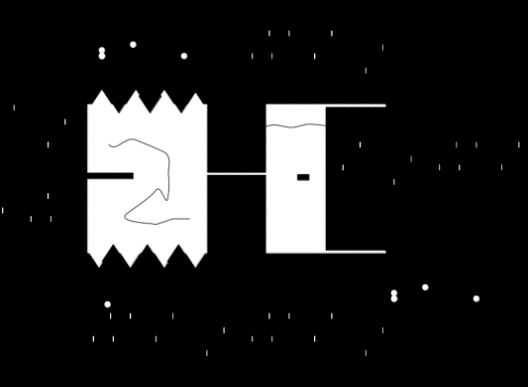
Apply morphological operations preprocessing to the image to make its features easier to analyze.
Input#
- Input Image
Type:
ImageColorImageGrayMeaning: The image to be processed
Output#
- Output Image
Type:
ImageColorImageGrayMeaning: The result image
Function#
Algorithm |
Function |
|---|---|
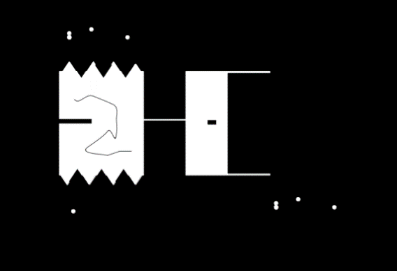
Open Morph |
First erosion, then dilation. Its function is to remove noise, eliminate small objects; separate objects at thin points; smooth the boundaries of larger objects without significantly changing their area. |
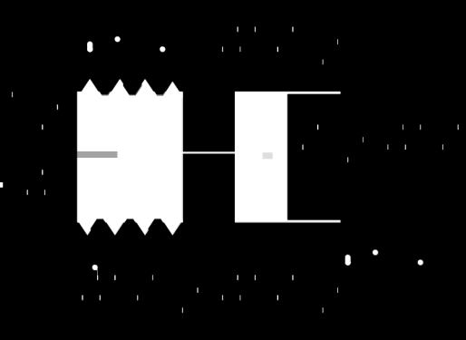
Close Morph |
First dilation, then erosion. Its function is to remove small holes (black areas); smooth object contours; bridge narrow breaks and grooves; fill in contour line gaps. |
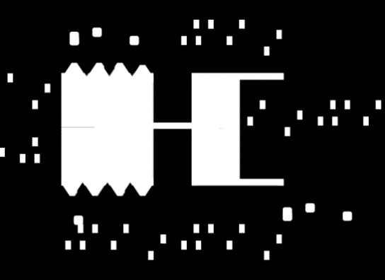
Dilate Morph |
Dilation merges all background pixels that touch the object into the object itself, expanding the boundaries outward. Dilation makes objects “fatter” and can be used to fill in scratches or holes in objects. |
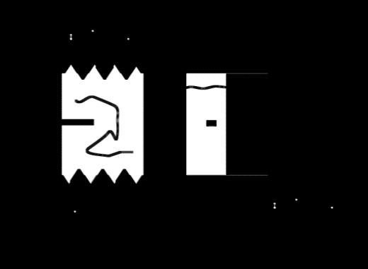
Erode Morph |
Erosion eliminates boundaries, causing the object to shrink inward. Erosion makes objects “thinner” and can be used to remove small interfering information in the image. |
Bottom Hat Morph |
The difference between the original image and the result of the closing operation. Black hat is used to detect defects and blemishes. |
Top Hat Morph |
The difference between the original image and the result of the opening operation. Top hat is used for background extraction. It can separate bright patches from their surroundings. When an image has a large background and small objects are relatively regular, top hat operations can be used for background extraction. |
Grad Morph |
The morphological gradient is the difference between the dilation and erosion of an image. It highlights the periphery of bright areas and provides a new approach for contour detection. |
Parameters#
- Morphology Method
Meaning: Select the morphological operation method
Range: Open Morph, Close Morph, Dilate Morph, Erode Morph, Bottom Hat Morph, Top Hat Morph, Grad Morph
- Morph Op Param - Morph Kernel Size:
Meaning:
Range: 3*3, 5*5, 7*7, 9*9, 11*11, 13*13, 15*15, 17*17, 19*19, 21*21
Examples#
Algorithm |
Example: Input Image |
Example: Output Image |
|---|---|---|
Open Morph |
|
|
Close Morph |
|
|
Dilate Morph |
|
|
Erode Morph |
|
|
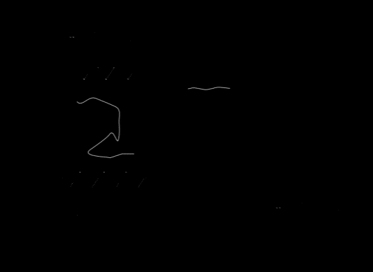
Bottom Hat Morph |
|
|
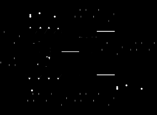
Top Hat Morph |
|
|
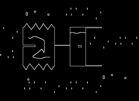
Grad Morph |
|
|
Image Transform#
Introduction#
Perform geometric transformations on an image.
Input#
- Input Image
Type:
ImageColorImageGrayMeaning: The image to be processed
Output#
- Output Image
Type:
ImageColorImageGrayMeaning: The result image
Function#
Algorithm |
Function |
|---|---|
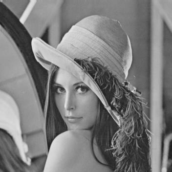
Flip |
Performs a mirror operation on the image. |
Rotate |
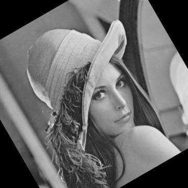
Rotates the image by a specified angle. |
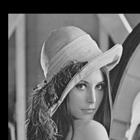
Translate |
Translates the image by a specified number of pixels horizontally and/or vertically. Rightward is the positive direction for horizontal translation, and downward is the positive direction for vertical translation. |
Parameters#
- Image Transform Method
Meaning: Select the image transformation method
Range: Flip, Rotate, Translate
- Flip - Flip Method:
Meaning: Select the mirror method
Range: Flip along both x and y axes, Flip along x-axis, Flip along y-axis
- Rotate - Rotate Method:
Meaning: Select the rotation method
Range: Rotate the image at its original size, Retain original content and expand canvas
- Rotate - Rotate Angle:
Meaning: The angle of rotation
Range: [0, 180]
- Translate - Horizontal Translate:
Meaning: The number of pixels to translate horizontally
Range: [0, MAX]
- Translate - Vertical Translate:
Meaning: The number of pixels to translate vertically
Range: [0, MAX]
Examples#
Algorithm |
Example: Input Image |
Example: Output Image |
|---|---|---|
Flip |
|
|
Rotate |
|
|
Translate |
|
|
Threshold Seg#
Introduction#
Perform threshold filtering and segmentation to binarize the image based on pixel intensity.
Input#
- Input Image
Type:
ImageGrayMeaning: The image to be processed
Output#
- Output Image
Type:
ImageGrayMeaning: The result image
Function#
Algorithm |
Function |
|---|---|
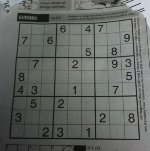
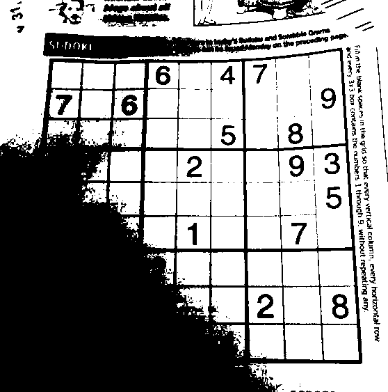
Global Auto Thresh |
Automatically binarizes the image into black and white. |
Global Manual Thresh |
Manually binarizes the image into black and white. |
Local Adapt Thresh |
Adaptive thresholding does not require a fixed threshold. Instead, it can set thresholds adaptively based on local image features, performing binarization accordingly. |
Gray Distance |
Calculates the absolute difference between each pixel and a grayscale threshold. |
Two Thresh |
Sets pixel intensity to 255 if it is between the minimum and maximum thresholds, otherwise sets it to 0. |
Parameters#
- Threshold Seg Method
Meaning: Select the threshold segmentation method
Range: Global automatic binarization, global manual binarization trans_dst - Range: Greater than the threshold, set to 255, otherwise 0; Greater than the threshold, set to 0, otherwise 255; Greater than the threshold, set to the threshold, otherwise retain the original pixel intensity; Greater than the threshold, retain the original pixel intensity, otherwise 0; Greater than the threshold, set to 0, otherwise retain the original pixel intensity
- Global Manual Thresh - Threshold:
Meaning: The threshold for global manual binarization
Range: [0, 255]
- Local Adapt Thresh - Adapt Max Val:
Meaning:
Range: [0, 255]
- Local Adapt Thresh - Adapt Method:
Meaning: Select the adaptive method
Range: Adaptive mean threshold, adaptive Gaussian threshold
- Local Adapt Thresh - Thresh Type:
Meaning: Select the threshold handling method
Range: When the pixel value is greater than the threshold, set to 255, otherwise 0; When the pixel value is greater than the threshold, set to 0, otherwise 255
- Local Adapt Thresh - Kernel Size:
Meaning:
Range: 3*3, 5*5, 7*7, 9*9, 11*11
- Local Adapt Thresh - Auto Adapt Var:
Meaning: Offset adjustment value
Range: [-100, 100]
- Gray Distance - Method
Meaning: Select the method to calculate grayscale distance
Range: Automatic threshold, manual threshold
- Gray Distance - Threshold
Meaning: This parameter is valid when manual threshold is selected
Range: [0, 255]
- Two Thresh - Min Val
Meaning: The lower limit of the grayscale intensity range to retain
Range: [0, 255]
- Two Thresh - Max Val
Meaning: The upper limit of the grayscale intensity range to retain
Range: [0, 255]
Examples#
Algorithm |
Example: Input Image |
Example: Output Image |
|---|---|---|
Global Auto Thresh |
|
|
Global Manual Thresh |
|
|
Local Adapt Thresh |
|
|
Gray Distance |
|
|
Two Thresh |
|
|
Calibration#
CalibTrans2D#
Introduction#
The 2D hand-eye calibration transformation operator is mainly used for robot positioning and grasping applications. Its function is to convert image pixel coordinates into robot coordinates, i.e., to convert pixel units into mm units.
Input#
- Input Pose
Type:
Pose2DPose2DListDescription: Pose in pixel coordinates
- Input File Path
Type:
std::stringDescription: Path to the 2D hand-eye calibration file (*.dmcalib)
Output#
- Output Pose
Type:
Pose2DPose2DListDescription: Resulting pose in robot coordinates
Parameters#
- File Path
Description: Path to the 2D hand-eye calibration file (*.dmcalib)
Range:
- File Input Settings
Description: Number of search lines within the ROI region
Range: From parameter settings, from input variable settings
Alg Distortion Correction#
Distortion correction is applied to the image#
Introduction#
Distortion correction of the camera image for subsequent processing
Input#
- Input Image
Type:
ImageGrayImageColorDescription: Input image type
- Input File Path
Type:
std::stringDescription: Path to the 2D hand-eye calibration file (*.dmcalib)
Output#
- Output Image
Type:
ImageGrayImageColorDescription: Distortion corrected image
Parameters#
- File Path
Description: Path to the 2D hand-eye calibration file (*.dmcalib)
Range:
Location#
Shape Match#
Introduction#
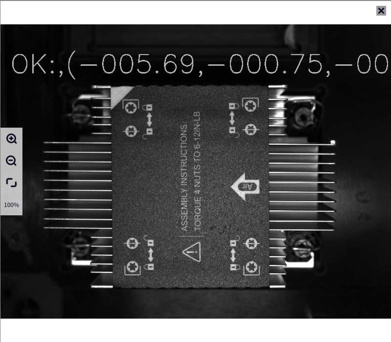
Shape matching is primarily used for target positioning in industrial settings. You need to first create a template using the 2D Template Creation Tool and then configure the template file in the solver before performing matching calculations.
Inputs#
- Input Detect Image
Type:
ImageColorImageGrayMeaning: Image to be detected
ROI#
- Input ROI
Type:
ROI2DRectROI2DRotatedRect
Outputs#
- Output Pose
Type:
Pose2DListMeaning: Recognized target pose, including x, y, and theta values
- Output Score
Type:
DoubleListMeaning: Recognition result score [0, 1], in the same order as the output pose
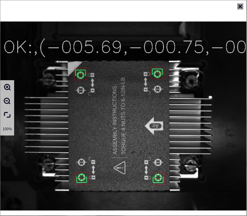
- Debug2D
Type:
Debuge2DMeaning: Result image
Parameters#
The parameters of this operator can be divided into Basic Parameters and Expert Parameters.
Easy Parameters#
- Template Path
Meaning: Select the dmtemp template path for matching
- ObjNumber
Meaning: Maximum number of recognized targets to output
Range: [1, 99]
- Corret Rate
Meaning: Accuracy of target recognition
Range: [1, 99]
- Speed Rate
Meaning: Speed of target recognition
Range: [1, 99]
Expert Parameters#
- Template Path
Meaning: Select the dmtemp template path for matching
- Min Score
Meaning: Minimum score for the output target
Range: [0.1, 1]
Note
Increasing the score will make the matching result more consistent with the trained template, but may result in missing outputs.
- Start Angle
Meaning: Starting angle relative to the template angle
Range: [-180, 180]
- Stop Angle
Meaning: Ending angle relative to the template angle
Range: [-180, 180]
- Max Overlap
Meaning: When there are multiple targets in the searched image, targets overlap with each other. The higher the overlap ratio, the larger the allowable overlapping area.
Range: [0.01, 0.99]
Note
Increasing the overlap ratio will affect the search speed and may produce erroneous search results.
- Num Levels
Meaning: Search acceleration strategy method; -1 means automatic. The smaller the number of pyramid levels, the slower the search speed and the higher the stability.
Range: -1, 0, 1, 2, 3, 4, 5, 6, 7
- Greediness
Meaning: Heuristic search. The smaller the setting, the earlier it exits the judgment loop, and the higher the possibility of not finding the object.
Range: [0, 1]
- Show Range
Meaning: Toggle display function
- Sort Method
Meaning: Dimension to sort by
Range:
X: Sort by X coordinate first
Y: Sort by Y coordinate first
- Is High HW Ratio Object
Meaning: When detecting slender parts incorrectly, you can enable this flag
Example#
Input Image
Output Image
Alg Detect2D Mark#
Introduction#
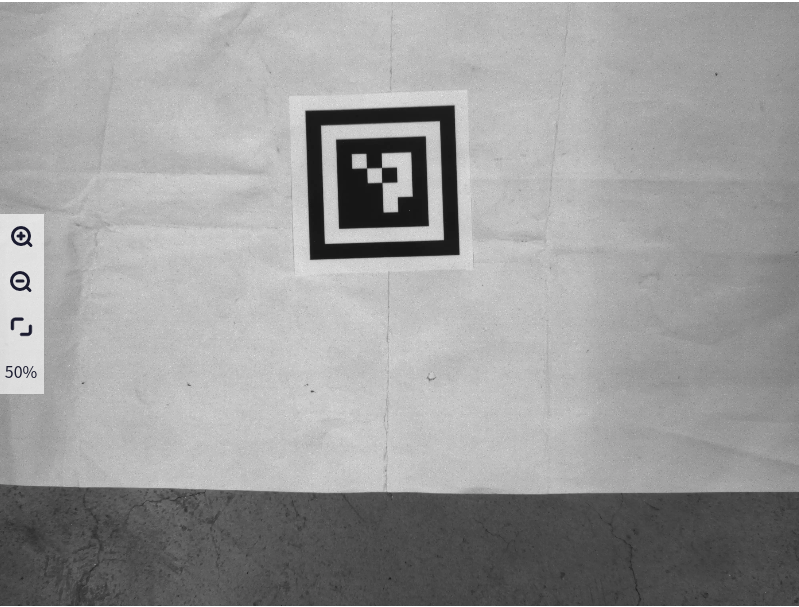
2DMark positioning is mainly used for target positioning in industrial scenarios, relying on recognizing 2D mark boards for positioning and grabbing operations.
Inputs#
- Input Image
Type:
ImageColorImageGrayMeaning: Image to be detected
Outputs#
- Mark Pose
Type:
Pose3DListMeaning: Recognized poses of all 2DMarks
- Detect Success
Type:
BoolMeaning: Whether the image contains detectable 2DMarks
- Output Debug2D
Type:
Debuge2DMeaning: Result image, showing the recognized 2DMark poses and their corner points
Parameters#
- Mark Type
Meaning: Default is DM-Mark2D-50A
- Intrinsic Path
Meaning: Intrinsic parameter file of the camera, obtained through intrinsic parameter calibration
Example#
Input Image
Output Image
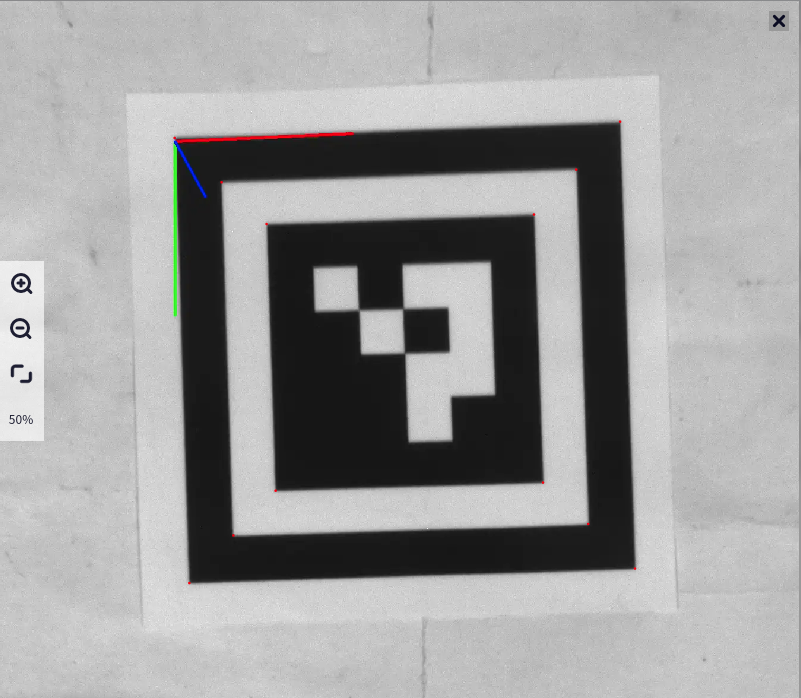
Image Processing#
Copy Image#
Overview#
Image Copy: Copies an image to a new variable.
Input#
- Input Image
Type:
ImageColorImageGrayMeaning: Image to be processed
Output#
- Output Image
Type:
ImageColorImageGrayMeaning: Resultant image
Create Mask Image#
Overview#
Draws information from graphical variables on the image and displays the drawing results.
Input#
- Input Image
Type:
ImageColorImageGrayMeaning: Image to be processed
- Input Region
Type:
RegionMeaning: Mask region
Output#
- Output Image
Type:
ImageColorImageGrayMeaning: Resultant image
Parameters#
- Drawing Method
Meaning: Drawing mode. “Original Image” draws directly from the original image pixels of the region, “Specified Color Fill” means the region is filled with the specified color’s pixel values
Range: Original Image, Specified Color Fill
- Foreground Drawing
Meaning: Only effective for the foreground region in the image
Range: Red, Green, Blue, Gray
- Background Drawing
Meaning: Only effective for the background region in the image
Range: Red, Green, Blue, Gray
Example#
Algorithm |
Example: Input Image |
Example: Output Image |
|---|---|---|
Original Image Drawing |
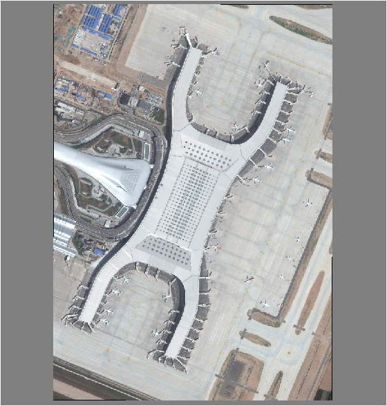
|
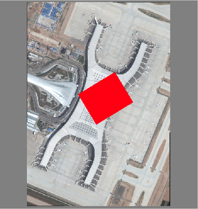
|
Specified Color Drawing |
|

|
Get Image Info#
Overview#
Gets information about an image, including its width, height, and number of channels.
Input#
- Input Image
Type:
ImageColorImageGrayMeaning: Image to be inspected
Output#
- Width
Type:
IntMeaning: Width of the image
- Height
Type:
IntMeaning: Height of the image
- Channel
Type:
IntMeaning: Number of channels in the image
Image Channel Decompose#
Overview#
Separates a color image (three-channel image) into its RGB or HSV channels, outputting three separated (grayscale) images.
Input#
- Input Image
Type:
ImageColorMeaning: Image to be processed
Output#
- Output Image 1
Type:
ImageGrayMeaning: R channel/H channel image variable
- Output Image 2
Type:
ImageGrayMeaning: G channel/S channel image variable
- Output Image 3
Type:
ImageGrayMeaning: B channel/V channel image variable
Parameters#
- Transform Method
Meaning: Transform Method
Range: BGR, HSV
Example#
Input Image
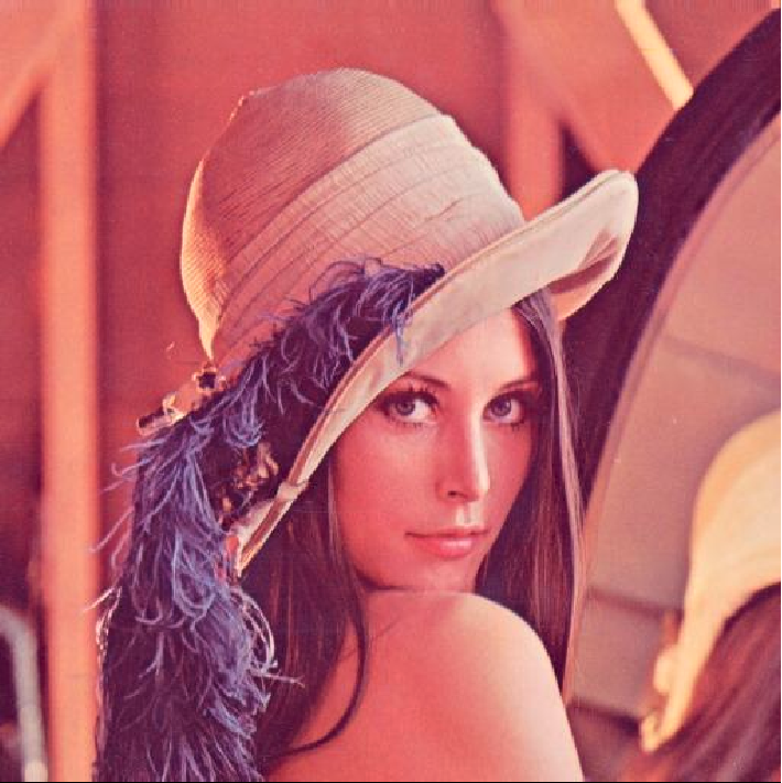
Output Image - BGR
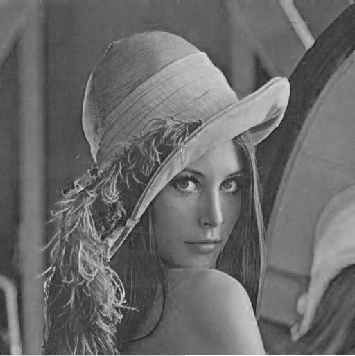
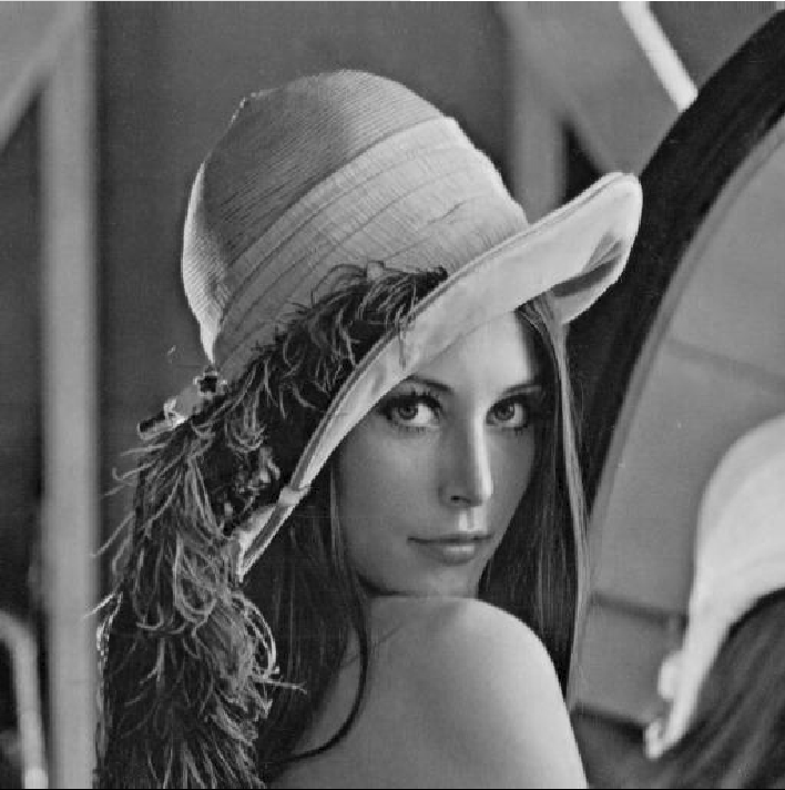
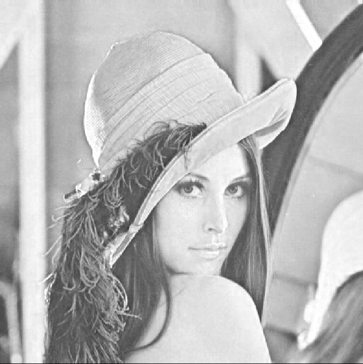
Output Image - HSV
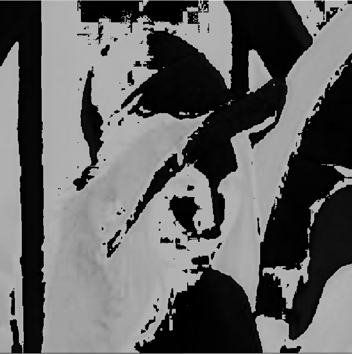
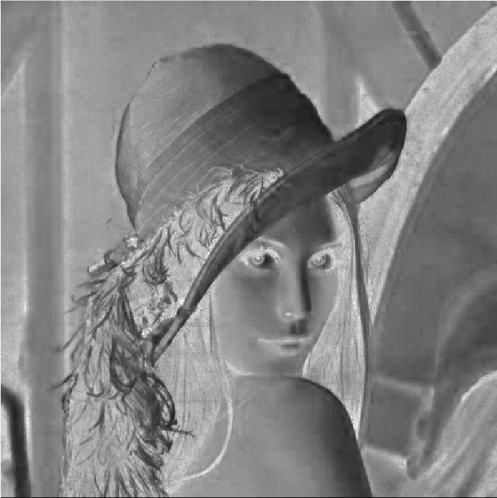
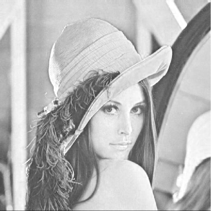
Image Channel Compose#
Overview#
Merges three separated (grayscale) image channels from an RGB or HSV image back into a color image (three-channel image).
Input#
- Input Image 1
Type:
ImageGrayMeaning: Processed R channel/H channel image variable
- Input Image 2
Type:
ImageGrayMeaning: Processed G channel/S channel image variable
- Input Image 3
Type:
ImageGrayMeaning: Processed B channel/V channel image variable
Output#
- Output Image
Type:
ImageColorMeaning: Resultant image
Parameters#
- Transform Method
Meaning: Transform Method
Range: BGR, HSV
Example#
Input Image - BGR
Input Image - HSV
Output Image
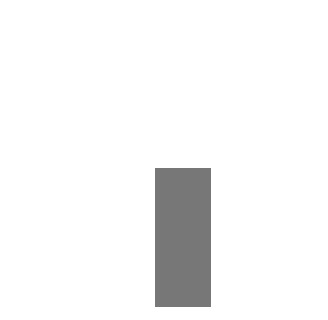
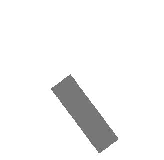
Region Logic Processing#
Overview#
Performs logical operations on 2 regions, including AND, OR, XOR.
Input#
- Input Region 1
Type:
RegionMeaning: Region to be processed 1
- Input Region 2
Type:
RegionMeaning: Region to be processed 2
Output#
- Output Region
Type:
RegionMeaning: Resultant Region
Parameters#
- Logic Operation Method
Meaning: Logical operation mode. AND outputs the overlapping region, OR outputs all regions, XOR outputs the differing regions
Range: AND, OR, XOR
Example#
Input Region 1
Input Region 2
Output Region - AND

Output Region - OR

Output Region - XOR

ROI#
Crop Image#
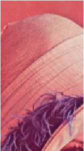
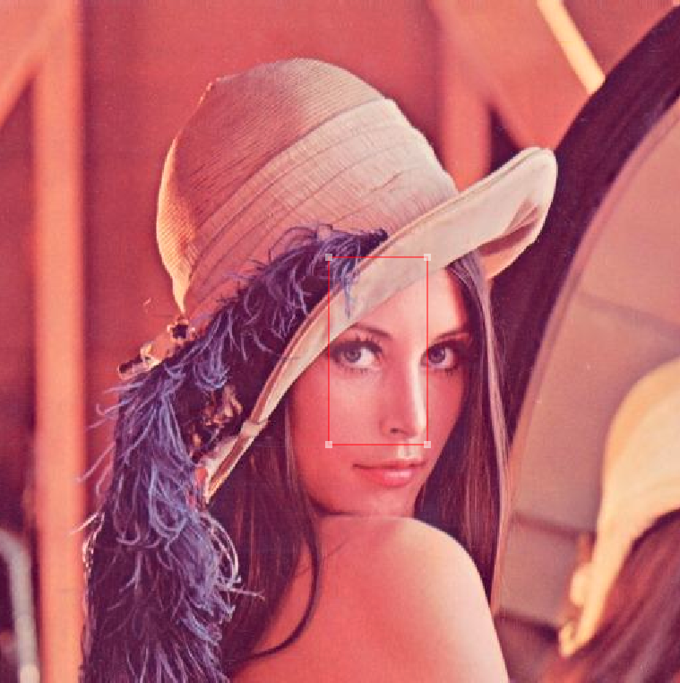
Introduction#
Image cropping can be used to crop an image to an appropriate area size.
Input#
- Input Image
Type:
ImageColorImageGrayDescription: The image to be processed
ROI#
- Input ROI
Type:
ROI2DRectROI2DRotatedRect
Output#
- Output Image
Type:
ImageColorDescription: Resultant image
Example#
Input Image
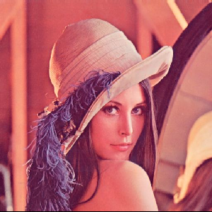
Output Image
ROI2Region#
Introduction#
The ROI to Region operator can create mask ROI areas for rectangular and rotated rectangular regions. The generated mask ROI variables can be used by shape matching operators. The mask ROI area represents the area within which the image will not be searched.
Input#
- Input Image
Type:
ImageColorImageGrayDescription: The image to be processed
ROI#
- Input ROI
Type:
ROI2DRectROI2DRotatedRect
Output#
- Output Region
Type:
RegionDescription: Resultant region
Example#
Input ROI
Output Region

ROI Create#
Introduction#
The ROI generation operator is used to create image ROI areas. This operator can create rectangular and rotated rectangular ROI areas. The generated ROI variables can be used by preprocessing, positioning, detection, and measurement modules’ operators. ROI areas allow operators to search and process within user-designed regions, effectively improving algorithm accuracy and efficiency.
Input#
- Input Image
Type:
ImageColorImageGrayDescription: The image to be processed
ROI#
- Input ROI
Type:
ROI2DRectROI2DRotatedRect
Example#
Input Image
ROI Correct#
Introduction#
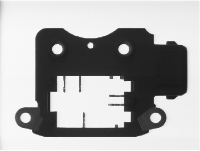
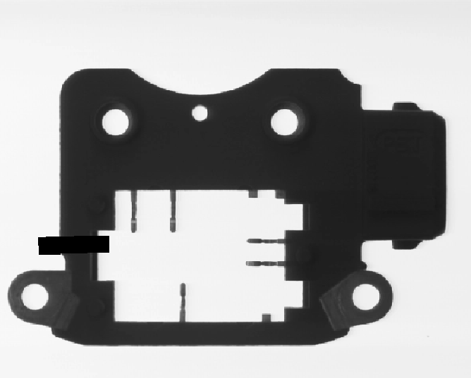
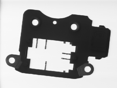
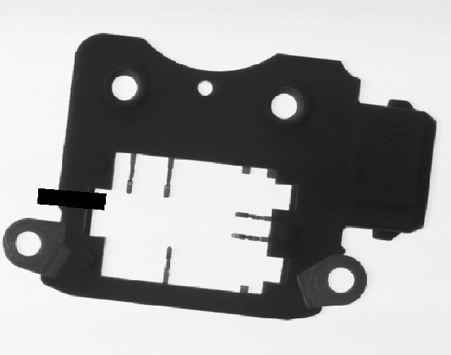
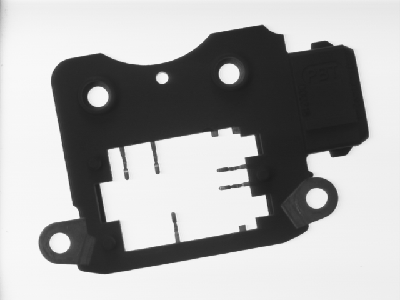
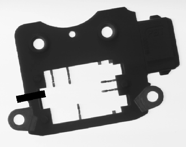
In actual field applications, the position of the workpiece to be inspected in the image may shift, so the ROI needs to follow these changes. Otherwise, it will not be detected. The ROI correction operator can solve this problem by creating a positioning reference so that the ROI moves along with the reference. ROI correction is generally an operator combination application, usually combined with the operators such as ROI generation, shape matching, and ROI correction. For example, if the ROI is not corrected, direct caliper measurement will cause the algorithm to fail. At this point, ROI correction can solve the problem.
Input#
- Input ROI
Type:
ROI2DRectROI2DRotatedRectDescription: The ROI to be corrected
- Input Pose
Type:
Pose2DDescription: The pose of the ROI to be corrected
Output#
- Output Image
Type:
ROI2DRectROI2DRotatedRectDescription: Correction result
Parameters#
- Pixel X
Description: The amount of correction for coordinate X
Range: [0, 2147483647]
- Pixel Y
Description: The amount of correction for coordinate Y
Range: [0, 2147483647]
- Pixel Angle
Description: The amount of correction for the angle
Range: [0, 360]
Example#
Scenario |
Example: Input Image |
Example: Output Image |
|---|---|---|
Scenario 1 |
|
|
Scenario 2 |
|
|
Scenario 3 |
|
|
AlgRegion Transform#
Introduction#
The Region identified in the cropped image can be restored to the original image coordinate system.
Input#
- Input Region
Type:
RegionDescription: The Region to be transformed
- Input Crop Rect
Type:
ROI2DRectROI2DRotatedRectRect2DRotatedRect2DDescription: The cropped region on the original image
Output#
- Output Region
Type:
RegionDescription: The area on the cropped image converted to the area on the original image
Example#
Input Region
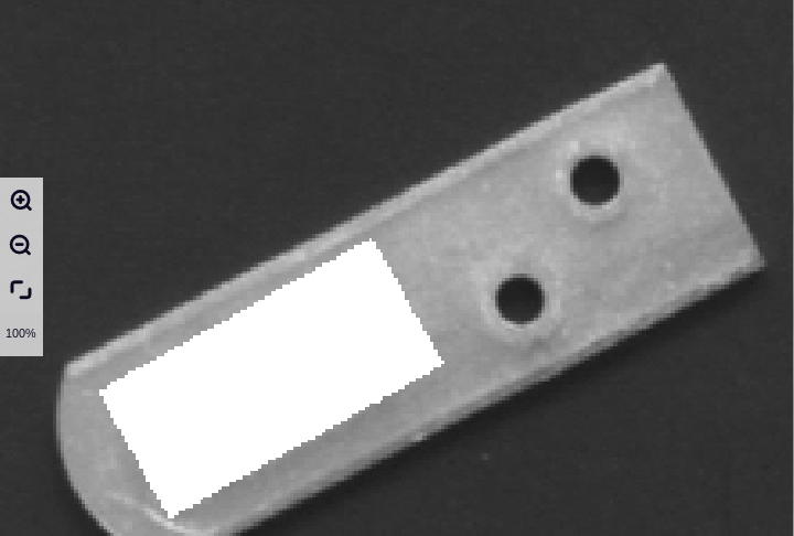
Input Crop Rect
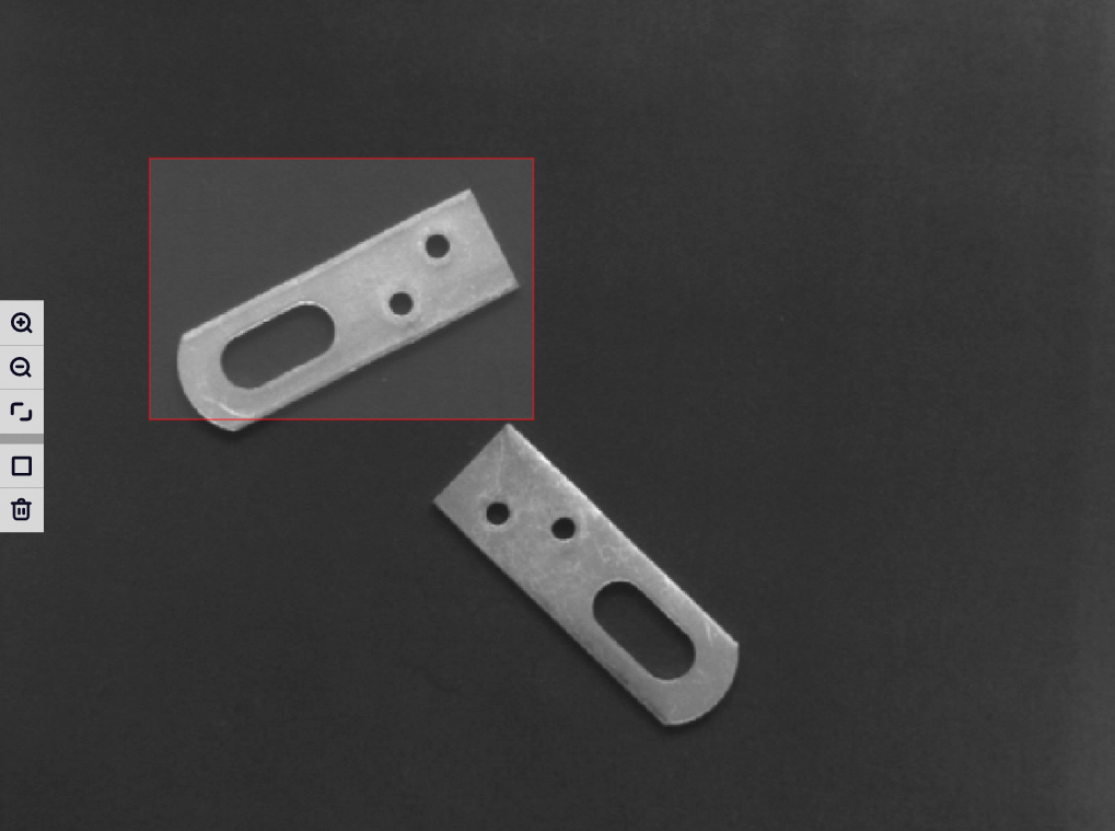
Output Region
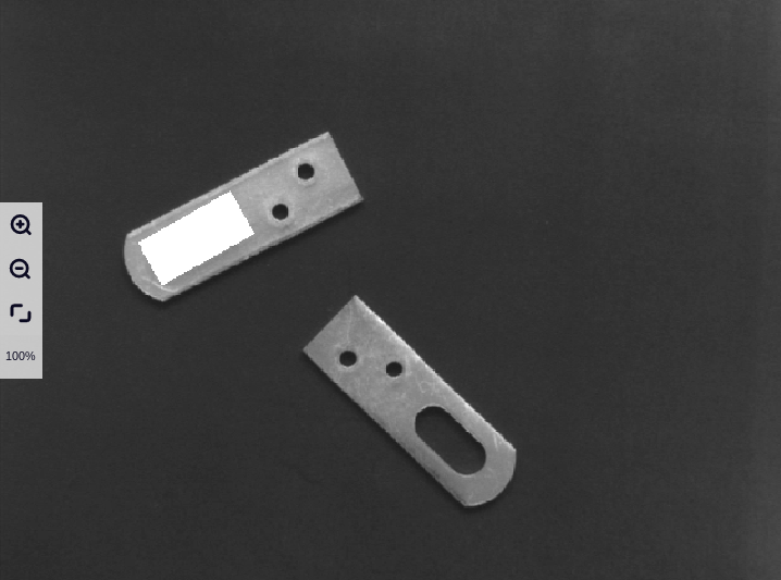
Detection#
Color Filter#
Introduction#
Color detection identifies areas in a color image that match user-defined colors based on the provided HSV color space range.
Input#
- Input Image
Type:
ImageColorMeaning: The image to be processed
Output#
- Region
Type:
RegionMeaning: Region where the color is extracted
- Mask
Type:
ImageGrayMeaning: Binary mask image of the extracted result
- Mask Result
Type:
Debuge2DMeaning: Result image of the extraction process
Parameters#
Color Picker HSV
Example#
Input Image

Output Image

Blob Detection#
Introduction#
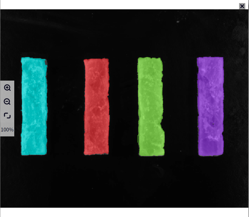
Blob analysis refers to the detection of a connected area in an image composed of similar colors, textures, and other features. Blob analysis involves binarizing the image to segment the foreground from the background and then detecting connected regions to identify blobs. Blob analysis provides information on the number, location, shape, and orientation of spots in an image for machine vision applications. It can be used for specific target positioning, presence detection, defect detection, quantity statistics, etc. It is particularly suitable for binarized images and high-contrast images. In the pharmaceutical and food packaging industries, blob analysis can detect the position and quality of objects.
Input#
- Input Image
Type:
ImageColorImageGrayMeaning: The image to be processed
ROI#
- Input ROI
Type:
ROI2DRectROI2DRotatedRect
Output#
- Object2D
Type:
RegionMeaning: Identified target region
- Result Pose
Type:
Pose2DListMeaning: Pose of the identified result
- Result Area
Type:
DoubleListMeaning: Size of the area
- Mask Image
Type:
Debuge2DMeaning: Result image mask
Parameters#
- Max Numbers
Meaning: The maximum number of targets identified
Range: [1, 2147483647]
- Blob Color
Meaning: Color type
Range: White or Black, White, Black
- Sort Type
Meaning: Type of sorting
Range: Area, Angle, Long Edge, Short Edge
- Sorting
Meaning: Order of sorting
Range: Ascending, Descending
- Area Filtering Enable
Meaning: Toggle for area filtering
- Area Range
Meaning: Range for area filtering
Range: [1, 2147483647]
- Angle Filter Enabled
Meaning: Toggle for long edge filtering
- Angle Range
Meaning: Range for long edge filtering
Range: [1, 2147483647]
- Short Len Filter Enabled
Meaning: Toggle for short edge filtering
- Short Range
Meaning: Range for short edge filtering
Range: [1, 2147483647]
Example#
Input Image
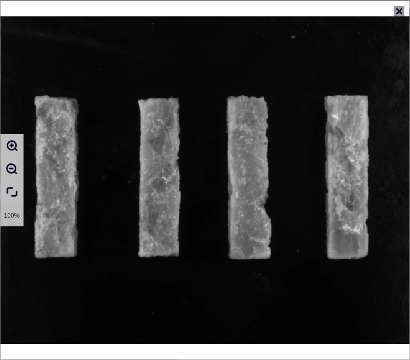
Output Image
Exit Detection#
Introduction#
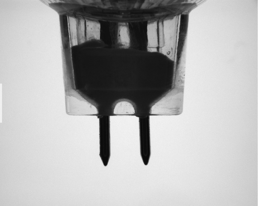
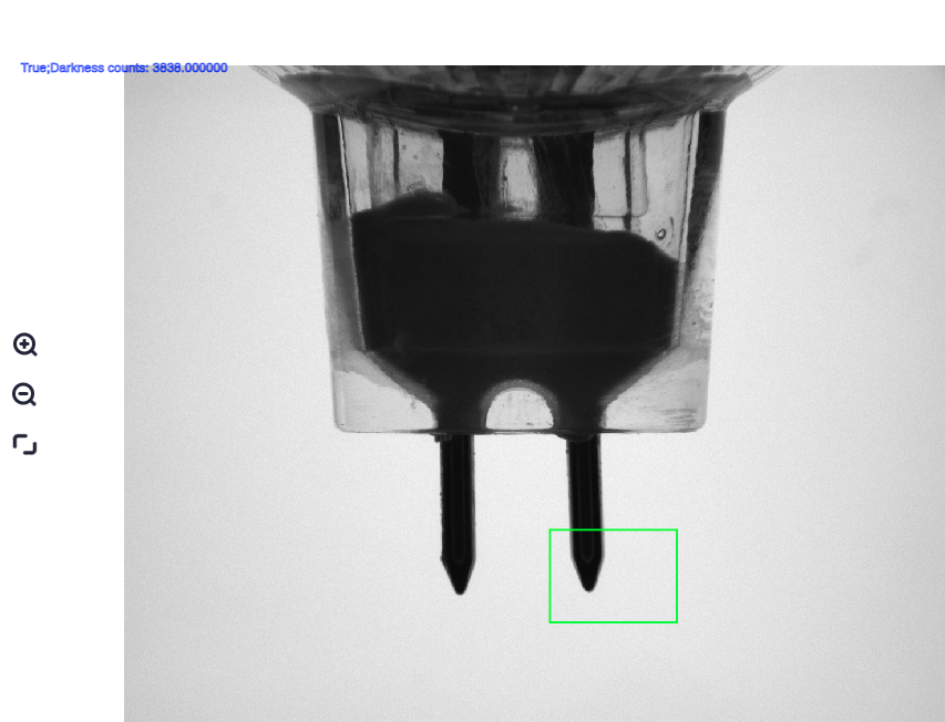
Presence detection is an operator that determines the presence or absence of something based on the number of black or white pixels or the contrast in an image.
Input#
- Input Image
Type:
ImageColorImageGrayMeaning: The image to be processed
ROI#
- Input ROI
Type:
ROI2DRectROI2DRotatedRect
Output#
- PointNum
Type:
DoubleMeaning: Number of black/white dots
- Result
Type:
BoolMeaning: Presence result
- Output Image
Type:
Debug2DMeaning: Result image
Parameters#
- Detect Method
Meaning: Method of presence detection
Range: Black Dot, White Dot, Contrast
- Filter Range
Meaning: Method of filtering presence
Range: [0, 2147483647]
Example#
Input Image
Output Image
Gray Analysis#
Introduction#
Gray analysis is used to statistically analyze the mean gray value and the standard deviation of gray values in an image.
Input#
- Input Image
Type:
ImageGrayMeaning: The image to be processed
Output#
- Mean Gray
Type:
DoubleMeaning: Mean of the gray image result
- Std Gray
Type:
DoubleMeaning: Standard deviation of the gray image result
- Gray Histogram List
Type:
DoubleListMeaning: Gray histogram list
Measure#
Caliper#
Introduction#
A caliper is a tool that finds two parallel lines within a specified area on a grayscale image and calculates the distance between these two lines. The caliper tool is commonly used to detect the width of an object.
Input#
- Input Image
Type:
ImageColorImageGrayMeaning: Image to be inspected
ROI#
- Input ROI
Type:
ROI2DRotatedRect
Output#
- First Edge Points
Type:
Vector2DListMeaning: The first set of detected edge points
- Second Edge Points
Type:
Vector2DListMeaning: The second set of detected edge points
- Intra Distance
Type:
DoubleListMeaning: Distance between the same pair of edges
- Inter Distance
Type:
DoubleListMeaning: Distance between pairs of edges
- Output Image
Type:
Debug2DMeaning: Result image
Parameters#
- Sigma
Meaning: Gaussian smoothing standard deviation of the image to be measured
Range: [0.1, 50.0]
- Min Edge Amp
Meaning: First derivative (gradient) value used to filter points on the edge curve
Range: [0, 99]
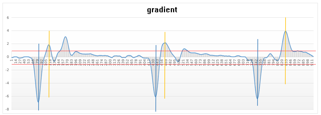
- Transition
Meaning: The type of grayscale transition, determines how to group edges into edge pairs
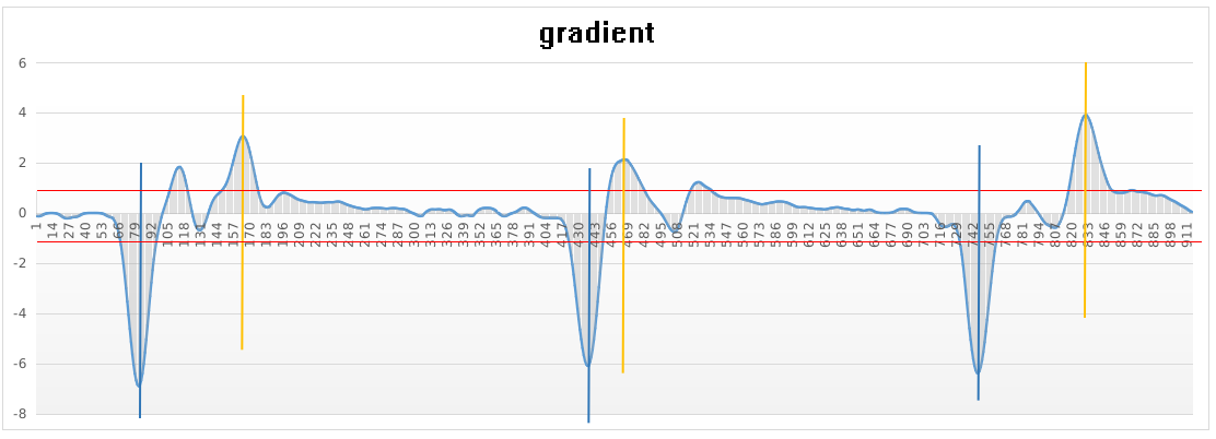
Range: All edges, strongest edge, positive edge, strongest positive edge, negative edge, strongest negative edge
Tip
Introduction to several types of edge pair polarities
All edges
Strongest edge
Positive edge
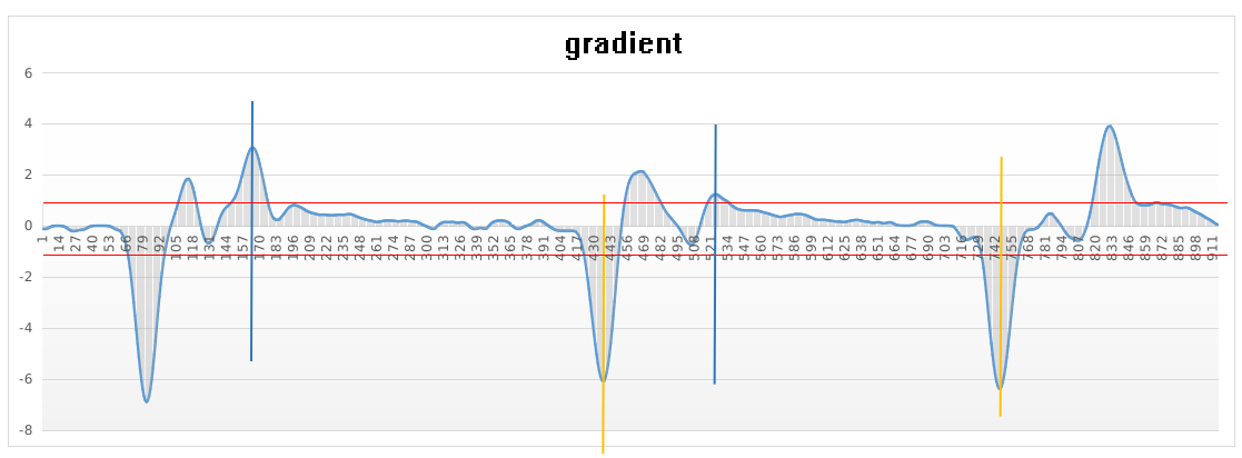
Strongest positive edge
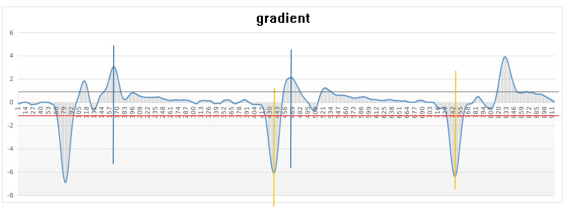
Negative edge
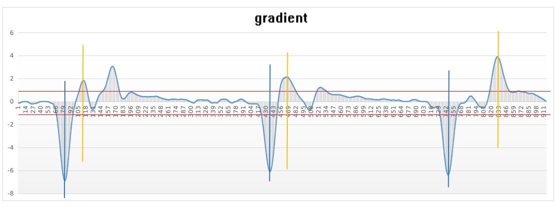
Strongest negative edge
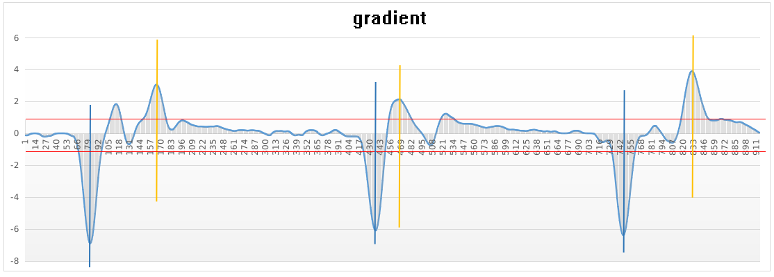
- Selection
Meaning: Used for filtering edge pairs by head and tail
Range: All edge pairs, first edge pair, last edge pair
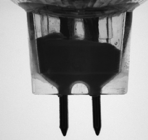
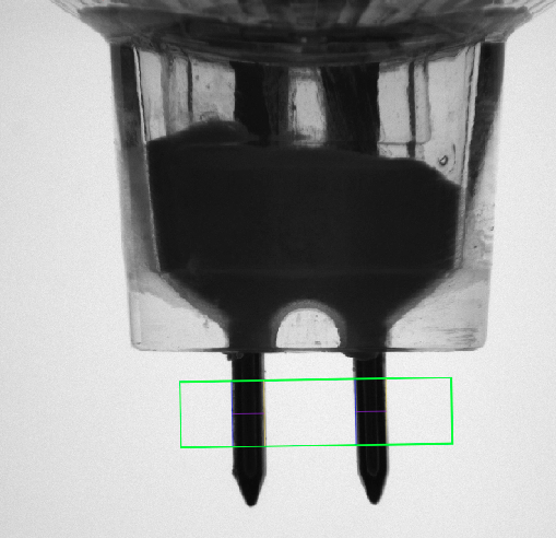
Examples#
Input Image
Output Image
Recognition#
Read Code#
Introduction#
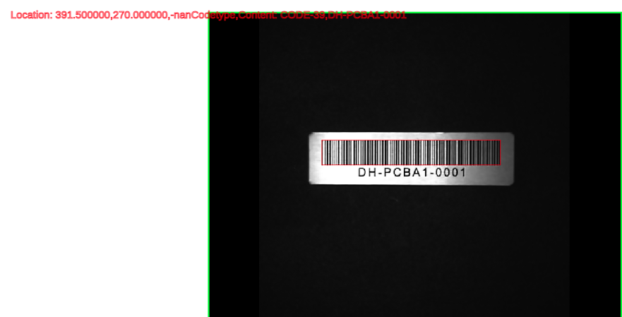
The code reading operator is used for identifying various types of barcodes, QR codes, DM codes, and ArUco codes.
Input#
- Input Image
Type:
ImageColorImageGrayMeaning: The image to be detected
ROI#
- Input ROI
Type:
ROI2DRectROI2DRotatedRect
Output#
- Result Pose
Type:
Pose2DListMeaning: The poses of the identified targets
- Result String
Type:
StringListMeaning: The result of the code reading
- 2D Code Types
Type:
StringListMeaning: The types of the recognized 2D codes
- Output Image
Type:
Debuge2DMeaning: The result image
Parameters#
- Angle Correction Enable
Meaning: Switch for angle correction
Range: [0, 300]
- Polarity
Range: Black on white, White on black
- Threshold
Meaning: Grayscale intensity value filtering
Range: [0, 255]
- Kernel Size
Meaning: Image filter kernel size
Range: 3*3, 5*5, 7*7, 9*9, 11*11, 13*13, 15*15, 17*17, 19*19, 21*21
- Code Types
Range: Barcode, QR code
- Barcode Types
Range: All barcode, EAN_UPC, CODEBAR, I25, CODE39, DATABAR, CODE93, DATABAR_EXP, CODE128
- 2D Code Types
Range: QR, DM, ArUco
Example#
Input Image
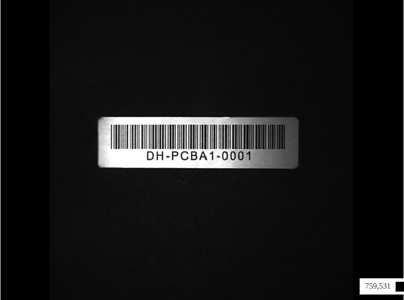
Output Image
Performance OCR#
Introduction#
The OCR operator is used for recognizing characters on objects and labels, mainly identifying English characters and numbers.
Input#
- Input Image
Type:
ImageColorImageGrayMeaning: The image to be detected
ROI#
- Input ROI
Type:
ROI2DRectROI2DRotatedRect
Output#
- Output String
Type:
StringListMeaning: The list of recognized strings
- Output Image
Type:
Debuge2DMeaning: The result image
Parameters#
- Case
Range: Auto, Uppercase, Lowercase
- Language
Range: English, Chinese, English + Chinese
- Mode
Meaning: Segmentation mode
Range: Auto page segmentation, Single line text, Word, Single character
- Remove Spaces
Meaning: Whether to remove spaces
- Special Case
Range: None, Recognize number 0 as letter O, Recognize letter O as number 0
Example#
Input Image

Output Image

3D Vision Operators#
IO#
Read Cloud#
Introduction#
Point cloud reading is used to read point clouds from a local path.
Input#
- Input Path
Type:
StringMeaning: File path
Output#
- Output Cloud
Type:
PointCloudPointCloudNormalMeaning: Output point cloud to the global variable list
Configuration Parameters#
- File Input Type
Meaning: Source of the file path
Range:
From parameter settings: Set the file path through the configuration parameter File Path
From input variables: Set the file path through the input variable Input Path
- File Path
Meaning: Select the path for point cloud reading
- Point Type
Range: Output XYZ point cloud, Output XYZNormal point cloud
Tip
The type of point cloud variable changes according to the configuration parameters.
Save Cloud#
Introduction#
Point cloud saving is used to save the point clouds processed by the software to the local path.
Input#
- Input Cloud
Type:
PointCloudPointCloudNormalMeaning: Input one of the point clouds from the global variable list
Configuration Parameters#
- File Save Type
Meaning: Source of the file path
Range:
From parameter settings: Set the file path through the configuration parameter File Path
From input variables: Set the file path through the input variable Input Path
- Save Path
Meaning: Select the path to save the point cloud
- Save Type
Range:
BinaryText
- Suffix
Range: None, Timestamp, Counter
ROI#
CloudClip#
Introduction#
Point cloud cropping can be used to crop point clouds to an appropriate area size.
Input#
- Input Cloud
Type:
PointCloudPointCloudNormalMeaning: Point cloud to be processed
Output#
- Debug3D
Meaning: The resulting point cloud image
Parameters#
- Box Input Type
Meaning: Choose the method for bounding box input
Scope: From parameter settings, from input variables
- Pose Input Type
Meaning: Choose the method for pose input
Scope: From parameter settings, from input variables
Tip
Bounding box input and pose input parameters are modified according to configuration parameters.
- Length:
Meaning: The length of the bounding box area
Range: [0, 999999]
- Width:
Meaning: The width of the bounding box area
Range: [0, 999999]
- Height:
Meaning: The height of the bounding box area
Range: [0, 999999]
- Translation X:
Meaning:
Range: [-999999, 999999]
- Translation Y:
Meaning:
Range: [-999999, 999999]
- Translation Z:
Meaning:
Range: [-999999, 999999]
- Rotation X:
Meaning:
Range: [-360, 360]
- Rotation Y:
Meaning:
Range: [-360, 360]
- Rotation Z:
Meaning:
Range: [-360, 360]
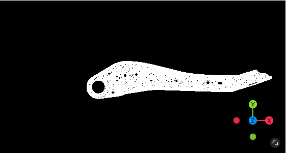
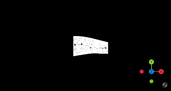
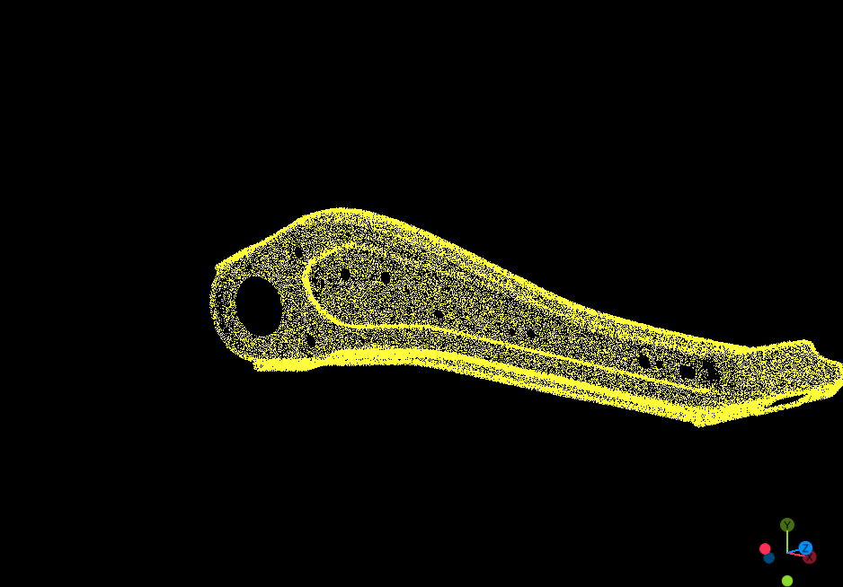
Examples#
Case |
Example: Input Point Cloud |
Example: Output Point Cloud |
|---|---|---|
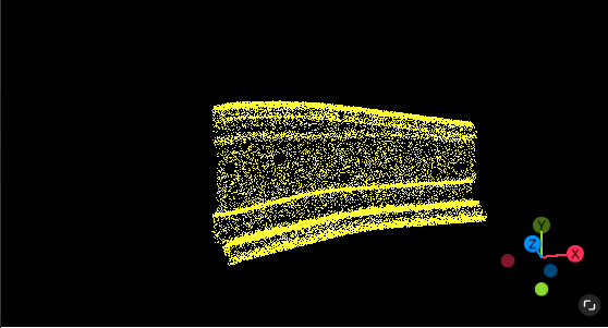
Case 1 |
|
|
Case 2 |
|
|
Sorting#
Cloud List Filter#
Introduction#
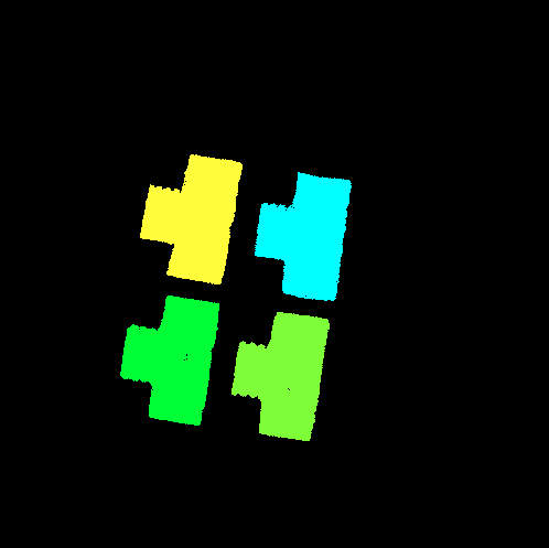
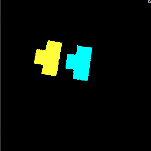
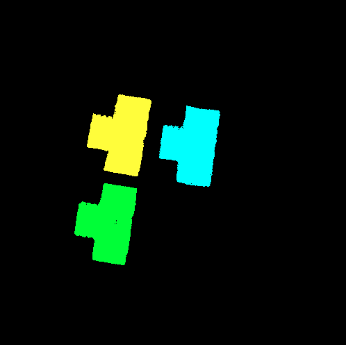
The point cloud array filter operator provides the function of filtering point clouds from the point cloud array. The filter condition can be set to the topmost point cloud, the number of points in the point cloud, or only get the point cloud with the most points. Among them, the “Topmost Point Cloud Filtering” method is used to obtain the topmost (multiple) workpiece point clouds when stacking identical workpieces (such as tubular workpieces).
Inputs#
- Input Cloud
Type:
PointCloudMeaning: Point cloud to be processed
Outputs#
- Output Cloud
Type:
PointCloudListMeaning: Resultant point cloud array
Parameters#
- Filter Method
Meaning: Choose the way to filter the point cloud array
Range: Get the topmost point cloud, filter by the number of points, get the point cloud with the most points
- Get Upper Cloud - Layer Distance
Meaning: Used for multi-layer point cloud filtering
Range: [0.2, 60]
- Filter by cloud Size - Max Size
Meaning: The maximum value of point count, used for point count filtering
Range: [5, 999999]
- Filter by cloud Size - Min Size
Meaning: The minimum value of point count, used for point count filtering
Range: [5, 999999]
Examples#
Method |
Example: Input Point Cloud |
Example: Output Point Cloud |
|---|---|---|
Get Upper Cloud |
|
|
Filter by cloud size |
|
|
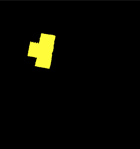
Get max size cloud |
|
|
Pose List Filter#
Introduction#
The pose array filter operator provides the function of filtering poses from the pose array. The filtering conditions can be set to “whether the input pose is within the ROI” and “whether the angle between the input pose and the reference pose is less than the threshold”.
Inputs#
- Input Pose
Type:
Pose3DListMeaning: Pose array to be processed
Outputs#
- Output Pose
Type:
Pose3DListMeaning: Resultant pose array
Parameters#
- Filter Method
Meaning: Choose the way to filter the pose array
Range: Bounding Box Range, Angle to Reference Pose
- Pose Input type
Meaning: Choose the input method of the reference pose
Range: Input from Reference Pose Parameters, Input from Input Reference Pose
- Angle Threshold
Meaning:
Range: [0.01, 360]
- Length:
Meaning: Length of the bounding box area
Range: [0, 999999]
- Width:
Meaning: Width of the bounding box area
Range: [0, 999999]
- Height:
Meaning: Height of the bounding box area
Range: [0, 999999]
- Translation X:
Meaning:
Range: [-999999, 999999]
- Translation Y:
Meaning:
Range: [-999999, 999999]
- Translation Z:
Meaning:
Range: [-999999, 999999]
- Rotation X:
Meaning:
Range: [-360, 360]
- Rotation Y:
Meaning:
Range: [-360, 360]
- Rotation Z:
Meaning:
Range: [-360, 360]
Cloud List Sort#
Introduction#
The point cloud array sorting operator provides the function of sorting the point cloud array. The sorting conditions can be set to point cloud points, point cloud bounding box volume, or point cloud center coordinates.
Inputs#
- Input Cloud
Type:
PointCloudListMeaning: Point cloud array to be processed
- Input Pose
Type:
Pose3DMeaning: Point cloud array to be processed
Outputs#
- Output Cloud
Type:
PointCloudListMeaning: Resultant point cloud array
- Index List
Type:
IntListMeaning: Resultant point cloud array
Parameters#
- Sorting Method
Meaning: Choose the way to sort the point cloud array
Range: Point Cloud Points, Bounding Box Size, Point Cloud Center Coordinates
- Ascend Order
Meaning: Ascending flag, False for descending, True for ascending
Range: [True, False]
- Pose Input Type
Meaning:
Range: Input from Reference Pose Parameters, Input from Input Reference Pose
- Cloud Center - Translation X:
Meaning:
Range: [-999999, 999999]
- Cloud Center - Translation Y:
Meaning:
Range: [-999999, 999999]
- Cloud Center - Translation Z:
Meaning:
Range: [-999999, 999999]
- Cloud Center - Rotation X:
Meaning:
Range: [-360, 360]
- Cloud Center - Rotation Y:
Meaning:
Range: [-360, 360]
- Cloud Center - Rotation Z:
Meaning:
Range: [-360, 360]
- Cloud Center - Center Axis:
Meaning:
Range: Point Cloud Center X Coordinate, Point Cloud Center Y Coordinate, Point Cloud Center Z Coordinate
Pose List Sort#
Introduction#
The pose array sorting operator provides the function of sorting the pose array. The sorting conditions can be set to “distance or angle between the input pose and the reference pose” or “projection of the input pose on the reference axis”, these 2 types of sorting methods.
Inputs#
- Input Pose
Type:
Pose3DListMeaning: Pose array to be processed
- Input Re Pose
Type:
Pose3DMeaning: Point cloud array to be processed
Outputs#
- Output Pose
Type:
Pose3DListMeaning: Resultant point cloud array
- Index List
Type:
IntListMeaning: Resultant point cloud array
Parameters#
- Sorting Method
Meaning: Choose the way to sort the pose array
Range: Euclidean Distance to Reference Pose, Angle to Reference Pose, Along X Axis, Along Y Axis, Along Z Axis
- Ascend Order
Meaning: Ascending flag, False for descending, True for ascending
Range: [True, False]
- Pose Input Type
Meaning:
Range: Input from Reference Pose Parameters, Input from Input Reference Pose
- Translation X:
Meaning:
Range: [-999999, 999999]
- Translation Y:
Meaning:
Range: [-999999, 999999]
- Translation Z:
Meaning:
Range: [-999999, 999999]
- Rotation X:
Meaning:
Range: [-360, 360]
- Rotation Y:
Meaning:
Range: [-360, 360]
- Rotation Z:
Meaning:
Range: [-360, 360]
Filter#
Cloud Outlier Remove#
Overview#
The outlier removal operator provides the function of removing outliers from the point cloud based on the distance between points. During the point cloud acquisition process, various external environmental and hardware factors often result in certain points being far from the target surface. These points are referred to as outliers.
Input#
- Input Cloud
Type:
PointCloudPointCloudNormalDescription: Point cloud to be processed
Output#
- Output Cloud
Type:
PointCloudPointCloudNormalDescription: Point cloud after filtering
Parameters#
- Filter Method
Description: Select the method for outlier filtering
Options: Statistical Filtering, Radius Filtering
- Statistics Filter - K Mean
Description: The number of neighboring points used for calculating the average distance and standard deviation between points, typically chosen between 5 and 10
Range: [2, 10000]
- Statistics Filter - Thresh
Description: The threshold factor for outlier removal, which is a multiple of the distance standard deviation. Usually, a value between 1 and 2 can remove a large number of outliers
Range: [0.1, 1000]
- Statistics Filter - Loop
Description: The number of iterations for outlier removal. After each iteration, the average distance and standard deviation between points will decrease, and removal is performed again based on the updated distance threshold
Range: [1, 10000]
- Radius Filter - Filter Radius
Description:
Range: [0.1, 1000]
- Radius Filter - Neighbor Number
Description:
Range: [1, 10000]
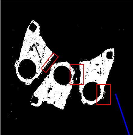
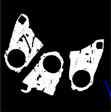
Examples#
Input Point Cloud
Output Point Cloud
Cloud sample#
Overview#
Downsampling provides the functionality to reduce the number of points in a point cloud, effectively speeding up subsequent operator processing. Downsampling offers two methods: random sampling and voxel sampling.
Input#
- Input Cloud
Type:
PointCloudPointCloudNormalDescription: Point cloud to be processed
Output#
- Output Cloud
Type:
PointCloudPointCloudNormalDescription: Point cloud after filtering
Parameters#
- Sampling Method
Description: Select the method for point cloud downsampling
Options: Voxel Sampling, Uniform Sampling
- Voxel Sampling - LeafX
Description: The sampling interval in the X-axis direction, generally set between 1 and 10
Range: [0.1, 10000]
- Voxel Sampling - LeafY
Description: The sampling interval in the Y-axis direction, generally set between 1 and 10
Range: [0.1, 1000]
- Voxel Sampling - LeafZ
Description: The sampling interval in the Z-axis direction, generally set between 1 and 10
Range: [0.1, 10000]
- Uniform Sampling - Uniform Sampling Value
Description:
Range: [0.01, 10000]
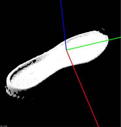
Examples#
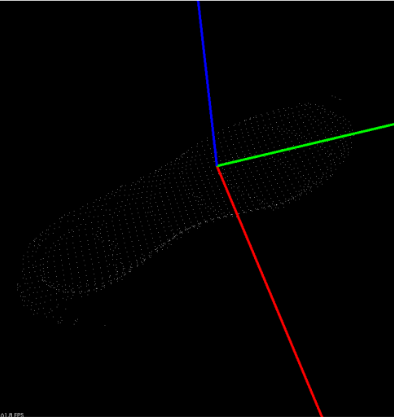
Input Point Cloud
Output Point Cloud
Segmentation#
CloudSegment#
Introduction#
Point cloud segmentation subdivides point cloud data into a series of point cloud blocks through a specific mechanism. Points within the same block have similar properties such as color, intensity, curvature, shape, etc. On one hand, this can reduce global processing to local processing within the region of interest; on the other, due to the similarity of point clouds within a block, it can simplify the point cloud storage structure and improve the efficiency of subsequent processing algorithms.
Input#
- InputCloud
Type:
PointCloudDescription: The point cloud to be processed
Output#
- OutputCloud
Type:
PointCloudListDescription: The resulting point cloud
Parameters#
- SegmentationMethod
Description: Choose the method of point cloud segmentation
Options: DistanceSegmentation, ConvexSegmentation
- DistanceSegmentation - DisMinSize
Description: The minimum number of points in a point cloud block after segmentation. If the number of points in a block is less than this value, it will be removed from the segmentation result. This can be used to filter out small objects or noise clumps. Set according to actual segmentation needs.
Range: [100, 999999]
- DistanceSegmentation - DisMaxSize
Description: The maximum number of points in a point cloud block after segmentation. If the number of points in a block is greater than this value, it will be removed from the segmentation result. This can be used to filter out large objects or backgrounds. Set according to actual segmentation needs.
Range: [100, 999999]
- DistanceSegmentation - DistanceThreshold
Description: The distance threshold between points in mm. Points with distances greater than this value will be considered to belong to different point cloud blocks. Set according to actual segmentation needs.
Range: [0.1, 100]
- ConvexSegmentation - ConMinSize
Description: The minimum number of points in a point cloud block after segmentation. If the number of points in a block is less than this value, it will be removed from the segmentation result. This can be used to filter out small objects or noise clumps. Set according to actual segmentation needs.
Range: [100, 999999]
- ConvexSegmentation - ConMaxSize
Description: The maximum number of points in a point cloud block after segmentation. If the number of points in a block is greater than this value, it will be removed from the segmentation result. This can be used to filter out large objects or backgrounds. Set according to actual segmentation needs.
Range: [100, 999999]
- ConvexSegmentation - VoxelResolution
Description: Voxel grid resolution for the original point cloud. Represents the smallest unit scale in the algorithm, meaning points within the grid will be treated with the same processing.
Range: [0.1, 100]
- ConvexSegmentation - SeedResolution
Description: The density of seed points in mm. Typically set to 2-5 times the voxel resolution. If a fine segmentation result is not required, set to a larger value.
Range: [0.1, 100]
- ConvexSegmentation - SpatialImportance
Description: Used in conjunction with normal weight. If the point clouds of two targets are close in space and their adjacent sections are essentially on the same plane, increase the spatial distance weight.
Range: [0.1, 5]
- ConvexSegmentation - NormalImportance
Description: Used in conjunction with spatial distance weight. If an object’s internal point cloud blocks are discontinuous due to occlusion or other factors, increase the normal vector weight threshold.
Range: [0.1, 100]
- ConvexSegmentation - ConcavityToleranceThreshold
Description: Convexity tolerance angle value. Generally set to 3-10 degrees. If smaller convex changes need to be detected, set to a smaller value.
Range: [0.1, 30]
- ConvexSegmentation - SmoothThreshold
Description: 0 represents no consideration of smoothness, 1 represents the strictest smoothness. Typically set to 0.5.
Range: [0.1, 1]
- ConvexSegmentation - UseExtendedConvexity
Description: Used in special scenarios. Typically set to false.
Options: [False, True]
- ConvexSegmentation - UseSanityCriterion
Description: Used in special scenarios. Typically set to false, not used.
Options: [False, True]
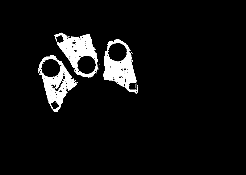
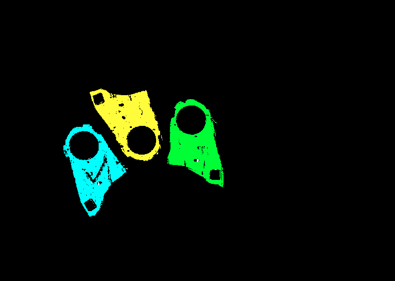
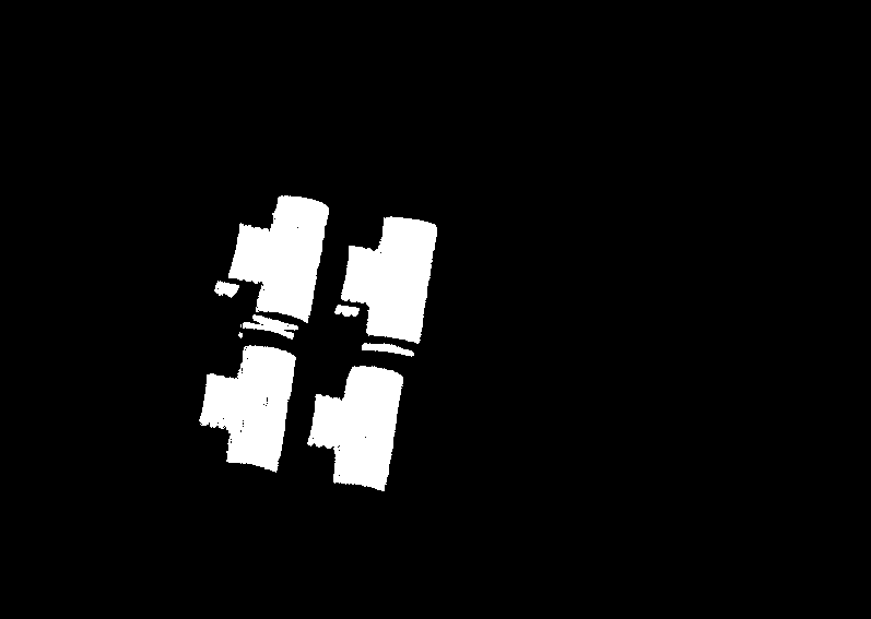
Examples#
Algorithm |
Example: Input Point Cloud |
Example: Output Point Cloud |
|---|---|---|
Distance Segmentation |
|
|
Convex Segmentation |
|
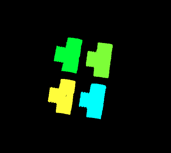
|
PointCloudRegionSeg#
Introduction#
Segment the point cloud based on segmentation regions of 2D images.
Input#
- PointCloudSource
Type:
PointCloudDescription: The point cloud to be processed
- PointCloudMap
Type:
PointCloudRegLUTDescription: The point cloud map to be processed
- InputRegion2D
Type:
RegionDescription: The region of the point cloud
Output#
- OutputCloud
Type:
PointCloudDescription: The resulting point cloud
Examples#
Input Point Cloud
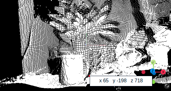
Output Point Cloud
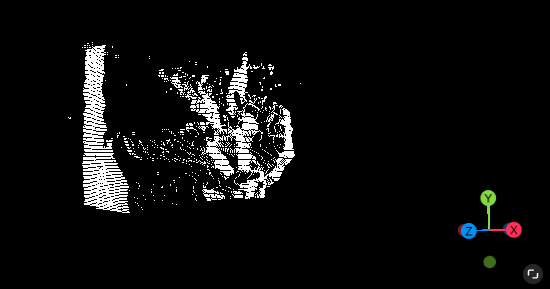
Point Cloud Region Growth#
Introduction#
Segment the point cloud using normal information.
Input#
- InputCloud
Type:
PointCloudNormalDescription: The point cloud to be processed
Output#
- OutputCloud
Type:
PointCloudListDescription: The resulting point cloud
Parameters#
- MinSize
Description: The minimum number of points in a point cloud block after segmentation. If the number of points in a block is less than this value, it will be removed from the segmentation result. This can be used to filter out small objects or noise clumps. Set according to actual segmentation needs.
Range: [100, 999999]
- MaxSize
Description: The maximum number of points in a point cloud block after segmentation. If the number of points in a block is greater than this value, it will be removed from the segmentation result. This can be used to filter out large objects or backgrounds. Set according to actual segmentation needs.
Range: [100, 999999]
- SearchNum
Description: The number of points searched in the vicinity of the initial point. More search points contribute to better segmentation results as the normal calculation will be more accurate.
Range: [1, 1000]
- SmoothThresh
Description: When clustering two points, the angle between their normals is calculated first. If the angle is less than or equal to the smoothness threshold, then the two points belong to the same cluster; otherwise, they do not.
Range: [0.1, 80]
- CurvatureThresh
Description: This represents the curvature of the surface where the two points are located. If the curvature is less than the threshold, the two points that belong to the same cluster; otherwise, they do not.
Range: [0.001, 40]
- ResidualThresh
Description: This allows you to set a residual threshold for testing points. Points below this threshold can enter a cluster selection condition.
Range: [0.001, 40]
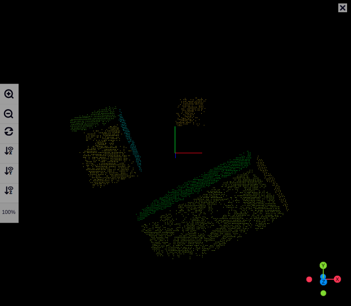
Examples#
Input Point Cloud
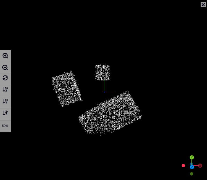
Output Point Cloud
Feature#
Feature#
Introduction#
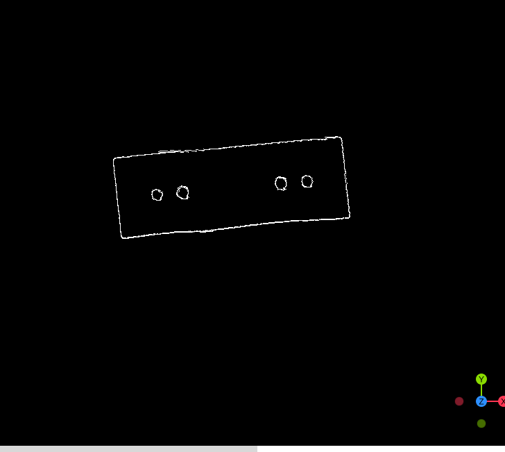
The edge detection operator provides the function of detecting the edges of point clouds. This function can be used as a preprocessing step for operators such as circle fitting, matching, etc.
Input#
- Input Cloud
Type:
PointCloudNormalMeaning: The point cloud to be processed
Output#
- Output Cloud
Type:
PointCloudMeaning: Resultant point cloud
Parameters#
- Angle Threshold
Meaning: The threshold for controlling the deviation of normal angles
Range: [1, 89]
- Search K
Meaning: The search radius used to determine whether a point is an edge point
Range: [1, 200]
Example#
Input Image
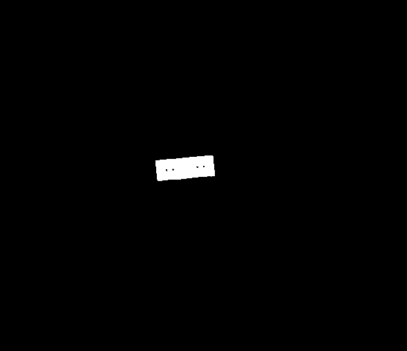
Output Image
Normal Estimation#
Introduction#
The normal estimation operator provides the function of calculating the normal vectors of point clouds. This operator can be added before operators that require point clouds with normal vectors as input.
Input#
- Input Cloud
Type:
PointCloudMeaning: The point cloud to be processed
Output#
- Output Cloud
Type:
PointCloudNormalMeaning: Resultant point cloud
Parameters#
- Compute Method
Meaning: Select the method of normal calculation
Range: NormalCompute, TangentLineCompute
- Normal Compute - Nor Search Method
Meaning: The method of searching for nearby points when calculating the normal vector of a point
Range: Use radius search, Use K neighborhood search
- Normal Compute - Nor Use Radius Search
Meaning: Search radius
Range: [0.01, 500]
- Normal Compute - Nor Use K-Mean Search
Meaning: Size of K value
Range: [3, 10000]
- Normal Compute - Nor Use Resolution Search
Meaning: Whether to use the search radius as the resolution coefficient for calculating the normal vectors of the scene point cloud
- Normal Compute - Use Redirection
Meaning: By setting the “viewpoint coordinates”, the direction is specified to point towards the “viewpoint coordinates”
Range: Viewpoint, Redirect
- Normal Compute - View PointX
Meaning:
Range: [-500, 500]
- Normal Compute - View PointY
Meaning:
Range: [-500, 500]
- Normal Compute - View PointZ
Meaning:
Range: [-500, 500]
- Tangent Line Compute - Tan Search Method
Meaning: The method of searching for nearby points when calculating the normal vector of a point
Range: Use radius search, Use K neighborhood search
- Tangent Line Compute - Tan Radius Search
Meaning: Search radius
Range: [0.01, 500]
- Tangent Line Compute - Tan K-Mean Search
Meaning: Size of K value
Range: [3, 10000]
- Tangent Line Compute - Tan Use Resolution Search
Meaning: Whether to use the search radius as the resolution coefficient for calculating the normal vectors of the scene point cloud
- Tangent Line Compute - Tangent Line Percent
Meaning: Tangent percentage
Range: [0.01, 500]
- Tangent Line Compute - Tangent Line Thresh
Meaning: Tangent threshold
Range: [0, 1000]
Example#
Algorithm |
Example: Input Image |
Example: Output Image |
|---|---|---|
Calculate Normal |
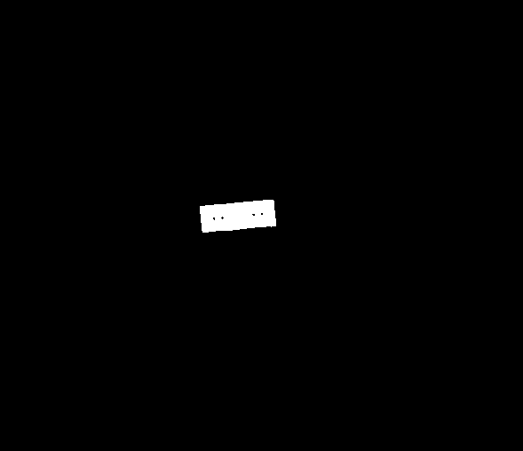
|
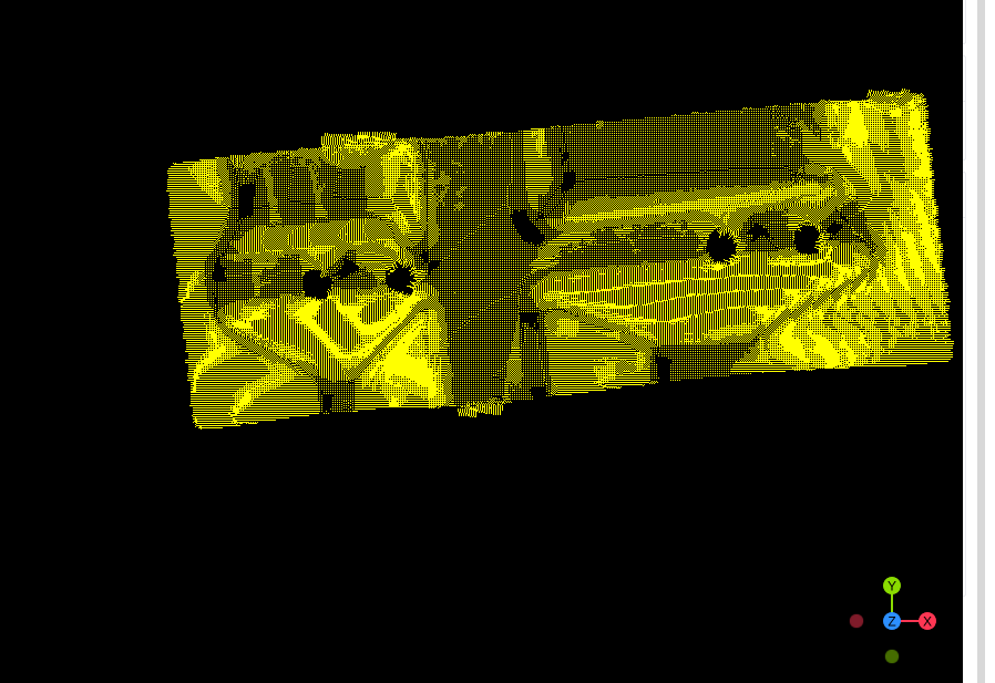
|
Calculate Tangent Line |
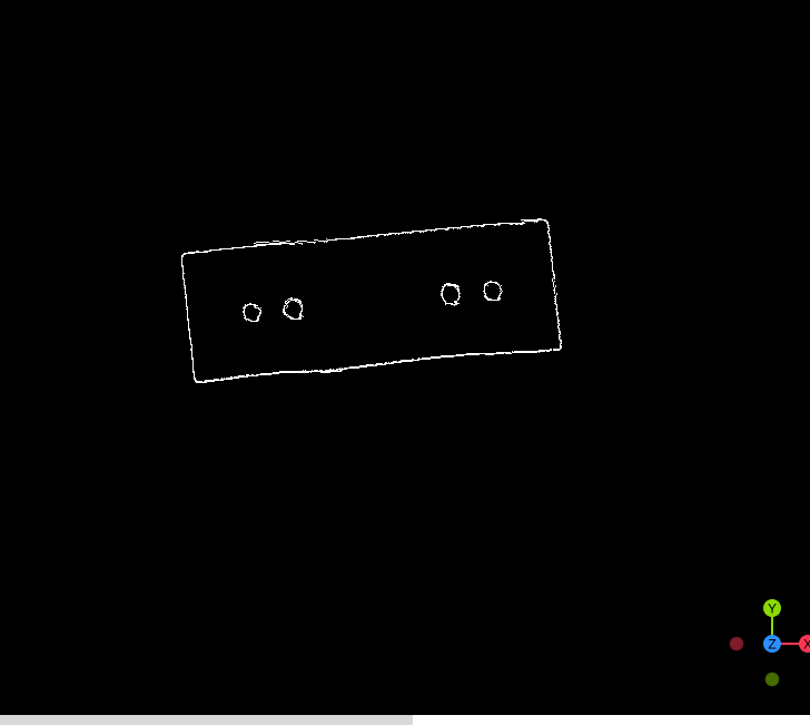
|
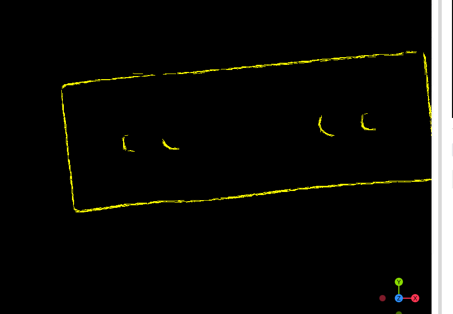
|
Transform#
Cloud Merge#
Introduction#
Merge two point clouds.
Input#
- Cloud_one
Type:
PointCloudPointCloudNormalDescription: Point cloud to be processed
- Cloud_two
Type:
PointCloudPointCloudNormalDescription: Point cloud to be processed
Output#
- Output Cloud
Type:
PointCloudPointCloudNormalDescription: Resulting point cloud
Example#
Input Image
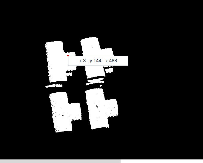
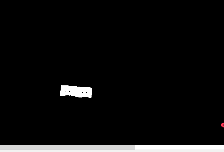
Output Image
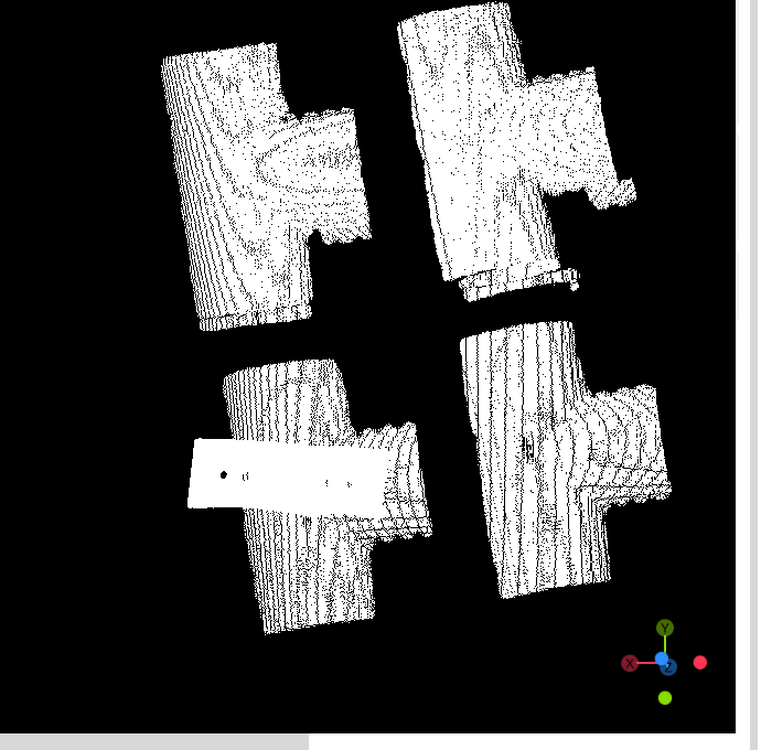
Point Mirror#
Introduction#
Point cloud symmetry transformation.
Input#
- Input Cloud
Type:
PointCloudDescription: Point cloud to be processed
- Input Plane Pose
Type:
Pose3DDescription: Input mirror plane
Output#
- Output Cloud
Type:
PointCloudDescription: Resulting point cloud
- Debug3D
Type:
Debug3DDescription: 3D result image
Parameters#
- Pose Input Type
Description: Input method of the mirror plane
Range: Input from plane parameters, Input from input mirror plane
- Mirror Plane
Description: Choose the symmetric plane
Range: XOY Plane, YOZ Plane, ZOX Plane
- Plane Pose Param - Translation X
Description:
Range: [-999999, 999999]
- Plane Pose Param - Translation Y
Description:
Range: [-999999, 999999]
- Plane Pose Param - Translation Z
Description:
Range: [-999999, 999999]
- Plane Pose Param - Rotation X
Description:
Range: [-360, 360]
- Plane Pose Param - Rotation Y
Description:
Range: [-360, 360]
- Plane Pose Param - Rotation Z
Description:
Range: [-360, 360]
Example#
Algorithm |
Example: Input Image |
Example: Output Image |
|---|---|---|
XOY Plane |
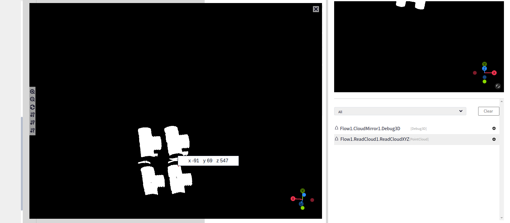
|
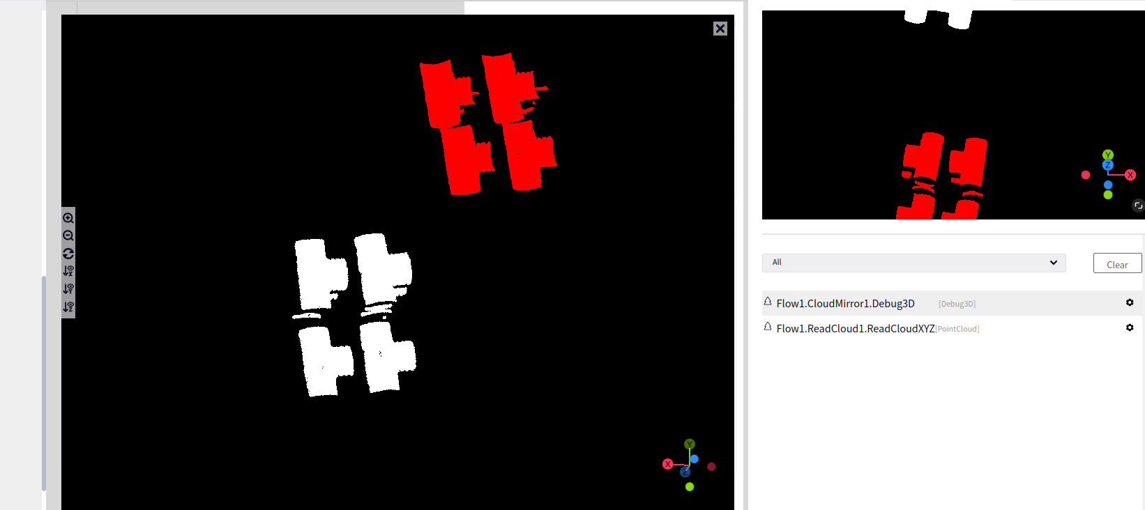
|
YOZ Plane |
|
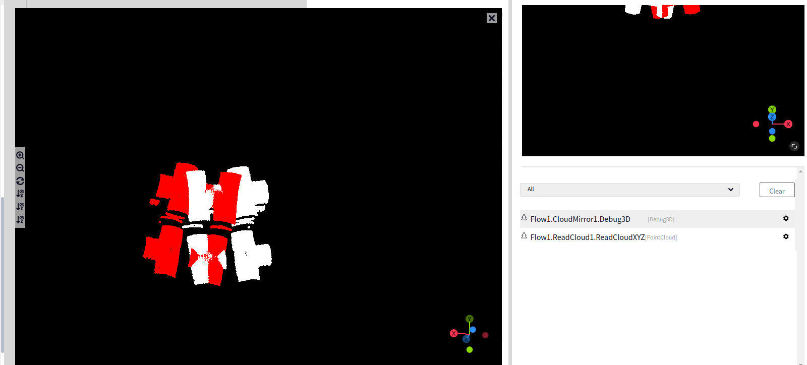
|
ZOX Plane |
|
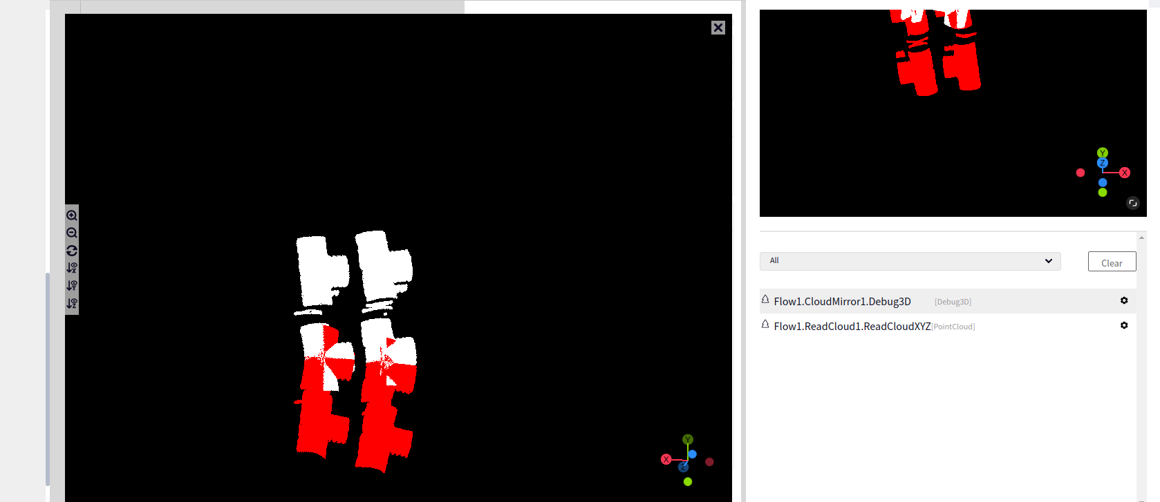
|
Cloud Projection#
Introduction#
The point cloud projection operator provides the function of projecting the input point cloud into a specified plane to form a plane point cloud.
Input#
- Input Cloud
Type:
PointCloudDescription: Point cloud to be processed
- Input Pose
Type:
Pose3DDescription: Input projection plane
Output#
- Output Cloud
Type:
PointCloudDescription: Resulting point cloud
- Debug3D
Type:
Debug3DDescription: 3D result image
Parameters#
- Pose Input Type
Description: Input method of the projection plane
Range: Input from plane parameters, Input from input projection plane
- Projection Plane
Description: Choose the projection plane
Range: XOY Plane, YOZ Plane, ZOX Plane
- Plane Pose Param - Translation X
Description:
Range: [-999999, 999999]
- Plane Pose Param - Translation Y
Description:
Range: [-999999, 999999]
- Plane Pose Param - Translation Z
Description:
Range: [-999999, 999999]
- Plane Pose Param - Rotation X
Description:
Range: [-360, 360]
- Plane Pose Param - Rotation Y
Description:
Range: [-360, 360]
- Plane Pose Param - Rotation Z
Description:
Range: [-360, 360]
Example#
Algorithm |
Example: Input Image |
Example: Output Image |
|---|---|---|
XOY Plane |
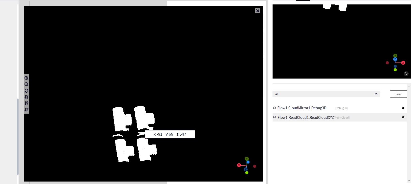
|
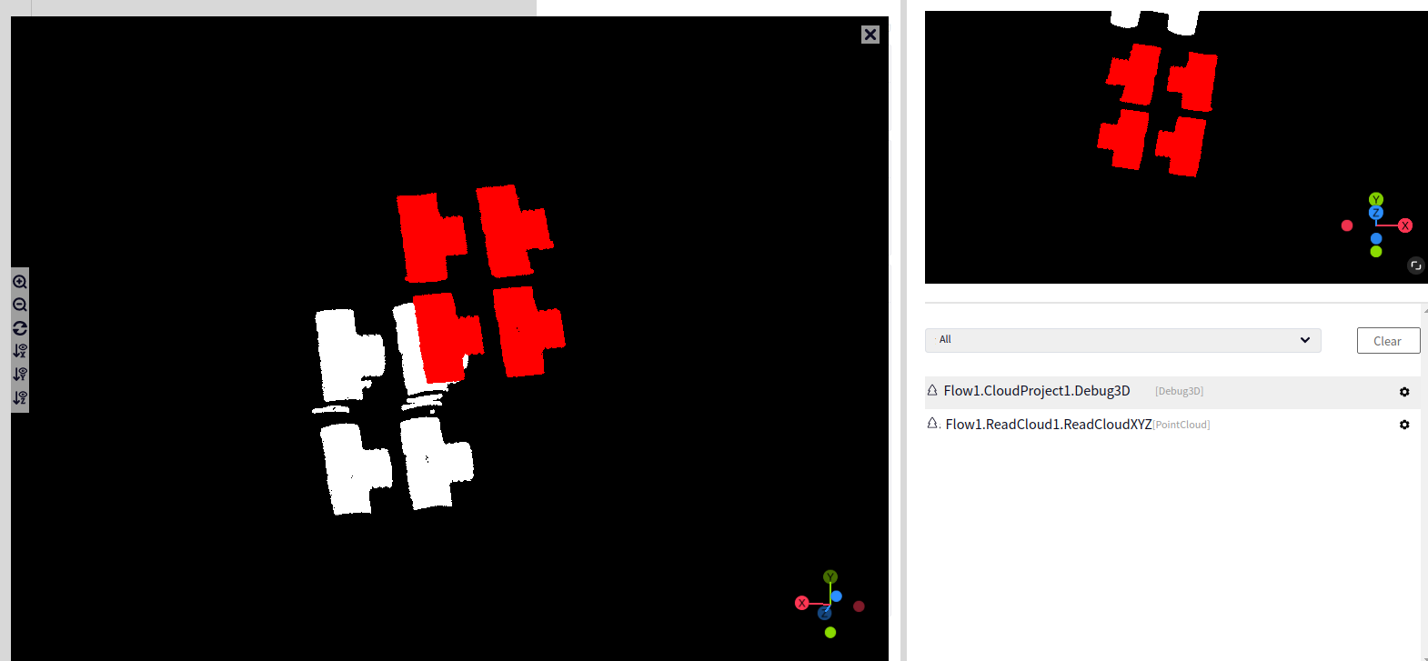
|
YOZ Plane |
|
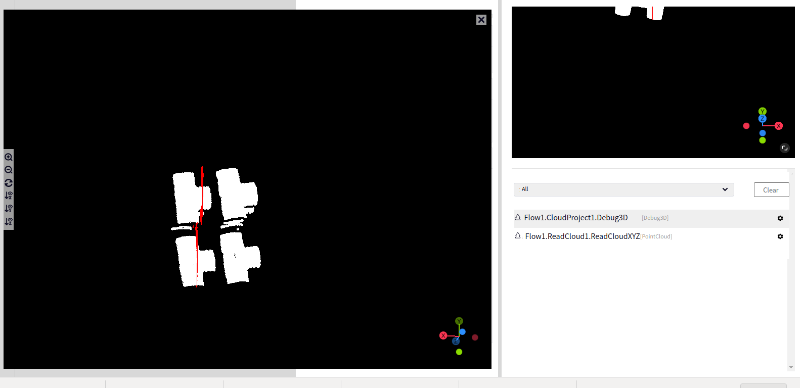
|
ZOX Plane |
|
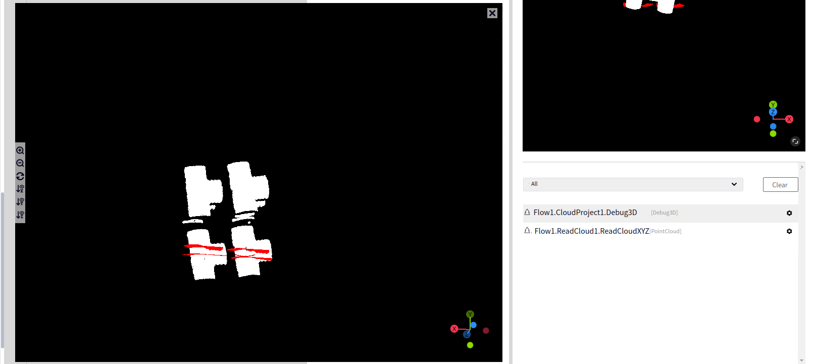
|
Cloud Size#
Introduction#
Point cloud point count functionality.
Input#
- Input Cloud
Type:
PointCloudPointCloudNormalDescription: Point cloud to be processed
Output#
- Output Cloud Size
Type:
IntDescription: The count of points in the point cloud
Cloud Trans#
Introduction#
The point cloud transformation operator provides the function of rotating and translating the point cloud.
Input#
- Input Cloud
Type:
PointCloudPointCloudNormalDescription: Point cloud to be processed
- Input Pose
Type:
Pose3DDescription: Input pose
Output#
- Output Cloud
Type:
PointCloudPointCloudNormalDescription: Resulting point cloud
Parameters#
- Pose Input Type
Description: The input method of the transformation pose
Range: Set from parameters, Set from input variable
- Trans Pose - Translation X
Description:
Range: [-999999, 999999]
- Trans Pose - Translation Y
Description:
Range: [-999999, 999999]
- Trans Pose - Translation Z
Description:
Range: [-999999, 999999]
- Trans Pose - Rotation X
Description:
Range: [-360, 360]
- Trans Pose - Rotation Y
Description:
Range: [-360, 360]
- Trans Pose - Rotation Z
Description:
Range: [-360, 360]
Example#
Input Image
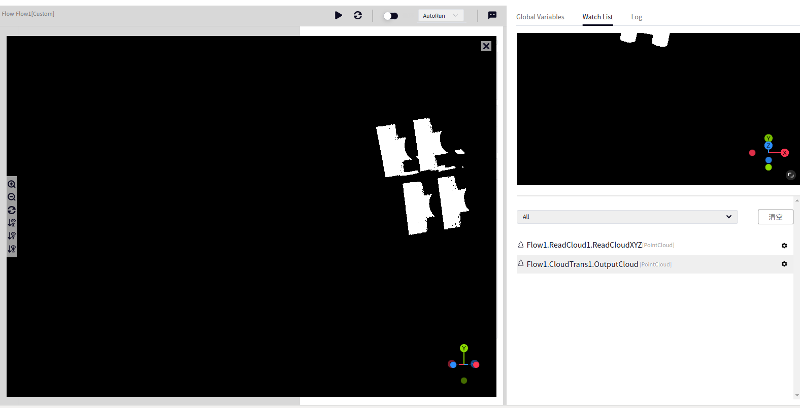
Output Image
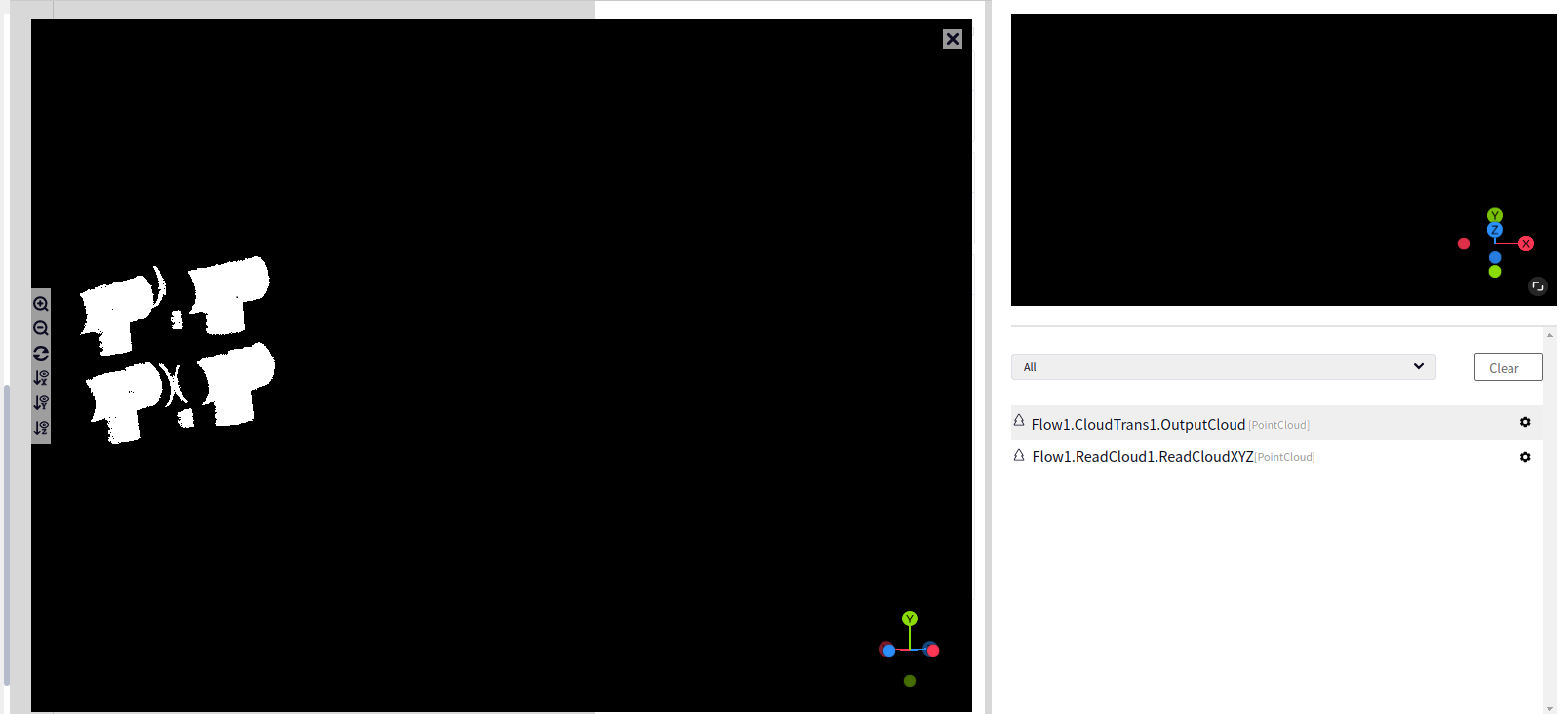
Pose Adjust#
Introduction#
The pose adjustment operator provides the function of adjusting the pose.
Input#
- Input Pose
Type:
Pose3DListDescription: Input pose
- Input Cloud
Type:
PointCloudDescription: Input point cloud
- Input Reference Pose
Type:
Pose3DDescription: Input reference pose
Output#
- Output Pose
Type:
Pose3DListDescription: Output adjusted pose
- Debug3D
Type:
Debug3DDescription: 3D result image
Parameters#
- Adjust Method
Description: Method of pose adjustment
Range: Adjust by inversion, Adjust by point cloud direction, Adjust by reference pose
- Adjust by Inversion - Inverse Axis
Description: Directly invert the pose
Range: XY Axis, YZ Axis, ZX Axis
- Adjust by Direction - Adjust Mode
Description:
Range: Adjust XYZ, Adjust Normal, Adjust XYZNormal
- Adjust by Direction - AdjustAxis
Description:
Range: X Axis, Y Axis, Z Axis
- Adjust by Direction - Length
Description:
Range: [5, 999999]
- Adjust by Direction - Width
Description:
Range: [5, 999999]
- Adjust by Direction - Height
Description:
Range: [5, 999999]
- Adjust by Reference - Pose Input Type
Description:
Range: Input from pose parameters, Input from input pose
- Adjust by Reference - Fix Axis
Description:
Range: Fix X Axis, Fix Y Axis, Fix Z Axis
- Adjust by Reference - Translation X
Description:
Range: [-999999, 999999]
- Adjust by Reference - Translation Y
Description:
Range: [-999999, 999999]
- Adjust by Reference - Translation Z
Description:
Range: [-999999, 999999]
- Adjust by Reference - Rotation X
Description:
Range: [-360, 360]
- Adjust by Reference - Rotation Y
Description:
Range: [-360, 360]
- Adjust by Reference - Rotation Z
Description:
Range: [-360, 360]
Pose Discrete#
Introduction#
The pose discretization operator provides the function of discretizing the pose.
Input#
- Input Pose
Type:
Pose3DListDescription: Input pose
Output#
- Output Pose
Type:
Pose3DListDescription: Output discretized pose
- Debug3D
Type:
Debug3DDescription: 3D result image
Parameters#
- Discrete Method
Description: Method of pose discretization
Range: Translation Transformation, Rotation Transformation
- Translation - Trans Plane
Description:
Range: XOY Plane, YOZ Plane, ZOX Plane
- Translation - Trans Range
Description:
Range: [0, 999999]
- Translation - Trans Step
Description:
Range: [0, 9999]
- Rotation - Rotation Axis
Description:
Range: Rotate around X-axis, Rotate around Y-axis, Rotate around Z-axis
- Rotation - Rotation Range
Description:
Range: [0, 360]
- Rotation - Rotation Step
Description:
Range: [0, 180]
Pose Trans#
Introduction#
The pose transformation operator provides the function of manipulating poses.
Input#
- Input Pose
Type:
Pose3DListDescription: Input pose
- Input Trans Pose
Type:
Pose3DDescription: Input reference pose
Output#
- Output Pose
Type:
Pose3DListDescription: Output transformed pose
Parameters#
- Pose Trans Method
Description: Method of pose transformation
Range: Pose Multiplication, Inverse Pose
- Pose Input Type
Description:
Range: Set from parameters, Set from input variable
- Multiply - Translation X
Description:
Range: [-999999, 999999]
- Multiply - Translation Y
Description:
Range: [-999999, 999999]
- Multiply- Translation Z
Description:
Range: [-999999, 999999]
- Multiply - Rotation X
Description:
Range: [-360, 360]
- Multiply - Rotation Y
Description:
Range: [-360, 360]
- Multiply - Rotation Z
Description:
Range: [-360, 360]
Cloud Clear#
Introduction#
The point cloud clearing operator provides the function of clearing point cloud data.
Input#
- Input Cloud
Type:
PointCloudPointCloudNormalDescription: Point cloud to be processed
Detection#
Bounding Box#
Introduction#
The bounding box operator provides functionality to output the bounding box of a cloud.
Tip
Note that the edges of the bounding box are usually parallel to the coordinate axes.
Input#
- Input Cloud
Type:
PointCloudMeaning: The point cloud to be processed
Output#
- Cloud Pose
Type:
Pose3DMeaning: The pose of the point cloud
- Cloud Size
Type:
Vector3DMeaning: The size of the point cloud
- Debug3D
Type:
Debug3DMeaning: 3D result image
Parameters#
- Compute Method
Meaning: The method to compute the bounding box
Range: PCA, MinVolume
- MinVolume - Epsilon
Meaning:
Range: [1, 20]
- MinVolume - PointSamples
Meaning:
Range: [10, 5000]
- MinVolume - GridSize
Meaning:
Range: [5, 50]
- MinVolume - DiamOptLoops
Meaning:
Range: [0, 50]
- MinVolume - GridSearchOptLoops
Meaning:
Range: [3, 50]
Example#
Input Image
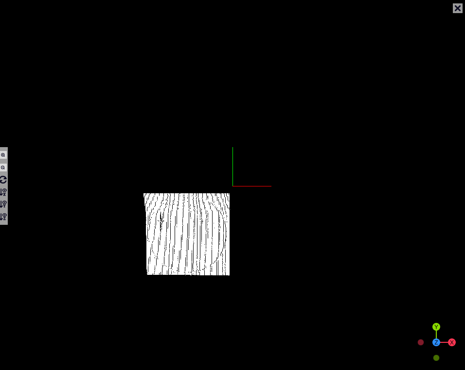
Output Image
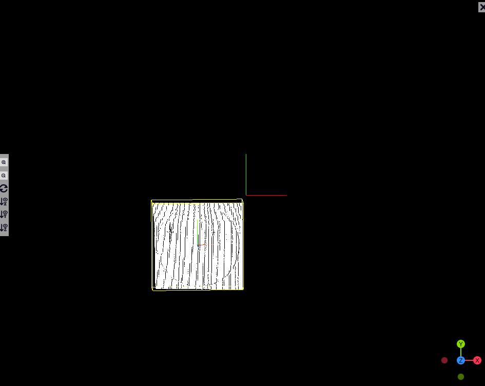
CircleFit#
Introduction#
The circle fitting operator provides functionality to fit circular point clouds. To avoid large areas of points (e.g., plane points where the hole is located) from affecting the result, edge detection can be added before the circle fitting operator to extract circular point clouds.
Tip
Note that this operator produces at most one fitting result. If no fitting result is found, the output variable “Has Result” returns false.
Input#
- Input Cloud
Type:
PointCloudPointCloudNormalMeaning: The point cloud to be processed
Output#
- Output Cloud
Type:
PointCloudPointCloudNormalMeaning: The resulting point cloud
- Circle Pose
Type:
Pose3DMeaning: The pose of the circle
- Circle Radius
Type:
DoubleMeaning: The radius of the circle
- Error
Type:
DoubleMeaning: Error
- Has Output
Type:
BoolMeaning: Whether there is a result
- Output Cloud
Type:
Debug3DMeaning: 3D result image
Parameters#
- Distance Threshold
Meaning: The distance threshold controls the distance between points and the fitted circle. A larger value will include more points from the input point cloud into the fitting result.
Range: [0.001, 99999]
- Normal Distance Weight
Meaning: The weight between the distance and the angle between normal vectors
Range: [0.001, 1]
- Min Radius
Meaning: The minimum reference radius of the sphere
Range: [1, 99999]
- Max Radius
Meaning: The maximum reference radius of the sphere
Range: [1, 99999]
- Max Iterations
Meaning: The maximum number of iterations allowed for solving
Range: [5, 99999]
- Overlap
Meaning: The minimum overlap rate between the fitted result and the original point cloud, used to evaluate the fitting result. Note that if this value is too high, the operator may output no result.
Range: [0.000001, 1]
- Output Circle
Meaning: Controls whether the output point cloud is the fitted point cloud
Example#
Input Image
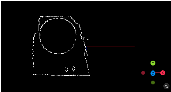
Output Image
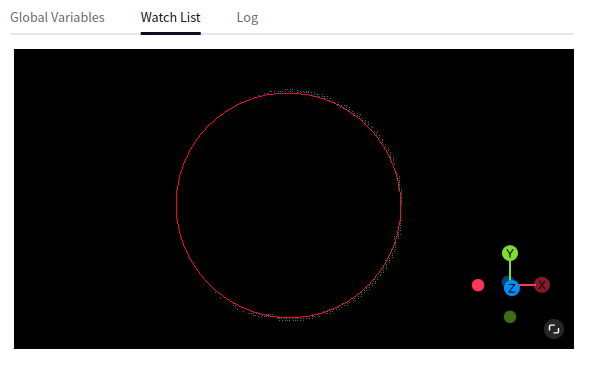
CylinderFit#
Introduction#
The cylinder fitting operator provides functionality to fit cylindrical point clouds.
Tip
Note that this operator produces at most one fitting result. If no fitting result is found, the output variable “Has Result” returns false.
Input#
- Input Cloud
Type:
PointCloudNormalMeaning: The point cloud to be processed
Output#
- Output Cloud
Type:
PointCloudNormalMeaning: The resulting point cloud
- Cylinder Pose
Type:
Pose3DMeaning: The pose of the cylinder
- Cylinder Radius
Type:
DoubleMeaning: The radius of the cylinder
- Cylinder Length
Type:
DoubleMeaning: The length of the cylinder
- Error
Type:
DoubleMeaning: Error
- Has Output
Type:
BoolMeaning: Whether there is a result
- Output Cloud
Type:
Debug3DMeaning: 3D result image
Parameters#
- Coarse Distance Threshold
Meaning: The distance threshold controls the distance between points and the fitted circle. A larger value will include more points from the input point cloud into the fitting result.
Range: [0.001, 99999]
- Fine Distance Threshold
Meaning: The distance threshold controls the distance between points and the fitted circle. A larger value will include more points from the input point cloud into the fitting result.
Range: [0.001, 99999]
- Min Radius
Meaning: The minimum reference radius of the sphere
Range: [1, 99999]
- Max Radius
Meaning: The maximum reference radius of the sphere
Range: [1, 99999]
- Fine Distance Threshold
Meaning: The weight between the distance and the angle between normal vectors
Range: [0.001, 1]
- Max Iterations
Meaning: The maximum number of iterations allowed for solving
Range: [5, 99999]
- Overlap
Meaning: The minimum overlap rate between the fitted result and the original point cloud, used to evaluate the fitting result. Note that if this value is too high, the operator may output no result.
Range: [0.000001, 1]
- Output Cylinder
Meaning: Controls whether the output point cloud is the fitted point cloud
Example#
Input Image
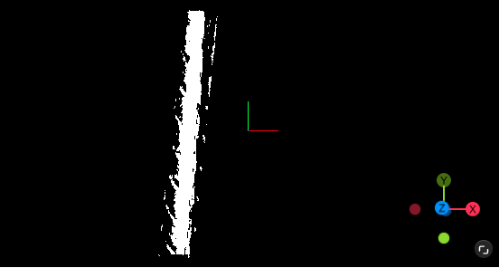
Output Image
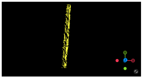
Plane Detection#
Introduction#
The plane detection operator provides functionality to estimate the bounding box of the top surface of a regular box, and based on this, estimate the center coordinates. It is mainly used in grasping tasks in simple scenes.
Input#
- Input Cloud
Type:
PointCloudListMeaning: The point cloud to be processed
Tip
A point cloud segmentation operator is required beforehand.
Output#
- Output Cloud List
Type:
PointCloudListMeaning: The resulting point cloud
- Plane Pose List
Type:
Pose3DListMeaning: The pose of the plane
- Plane Size List
Type:
Vector2DListMeaning: The size of the plane
- Debug3D
Type:
Debug3DMeaning: 3D result image
Parameters#
- Distance Threshold
Meaning: The distance threshold controls the distance between points and the fitted circle.
Range: [0.001, 99999]
- Max Iterations
Meaning: The maximum number of iterations allowed for solving
Range: [5, 99999]
- Output Plane
Meaning: Controls whether the output point cloud is the detected point cloud
Example#
Input Image
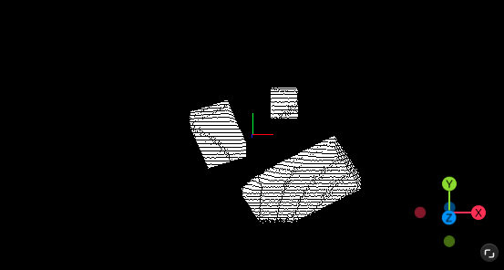
Output Image
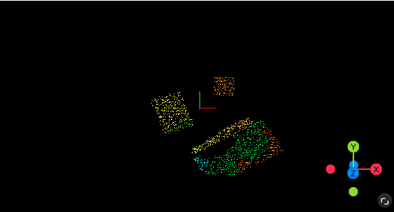
Plane Fit#
Introduction#
The plane fitting operator provides functionality to fit planar point clouds.
Tip
Note that this operator produces at most one fitting result. If no fitting result is found, the output variable “Has Result” returns false.
Input#
- Input Cloud
Type:
PointCloudNormalMeaning: The point cloud to be processed
Output#
- Output Cloud
Type:
PointCloudNormalMeaning: The resulting point cloud
- Plane Pose
Type:
Pose3DMeaning: The pose of the plane
- Plane Size
Type:
Vector2DMeaning: The size of the plane
- Max All Bias (All Points)
Type:
DoubleMeaning:
- Min All Bias (All Points)
Type:
DoubleMeaning:
- Has Output
Type:
BoolMeaning: Whether there is a result
- Output Cloud
Type:
Debug3DMeaning: 3D result image
Parameters#
- Fit Method
Meaning: The method to fit the plane
Range: GlobalFitting, PlaneFitting
- Maximum Allowed Error
Meaning:
Range: [0.001, 2147483647]
- Accept Percent
Meaning:
Range: [0.001, 100]
- Distance Threshold
Meaning: The distance threshold controls the distance between points and the fitted circle. A larger value will include more points from the input point cloud into the fitting result.
Range: [0.001, 2147483647]
- Normal Distance Weight
Meaning: The weight between the distance and the angle between normal vectors
Range: [0.001, 1]
- Max Iterations
Meaning: The maximum number of iterations allowed for solving
Range: [5, 99999]
- Planarity
Meaning: Used to evaluate the fitting result. Note that if this value is too high, the operator may output no result.
Range: [0.000001, 1]
- Output Plane
Meaning: Controls whether the output point cloud is the fitted planar point cloud. If checked, the fitted planar point cloud is output; otherwise, the point cloud outside the fitted planar point cloud is output (can be used to filter out planes).
Example#
Input Image
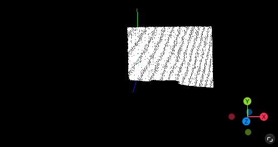
Output Image
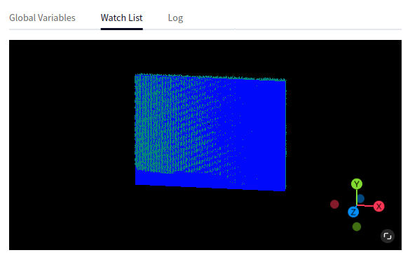
Sphere Fit#
Introduction#
The sphere fitting operator provides functionality to fit spherical point clouds.
Tip
Note that this operator produces at most one fitting result. If no fitting result is found, the output variable “Has Result” returns false.
Input#
- Input Cloud
Type:
PointCloudPointCloudNormalMeaning: The point cloud to be processed
Output#
- Output Point Cloud
Type:
PointCloudPointCloudNormalMeaning: The resulting point cloud
- Sphere Radius
Type:
DoubleMeaning: The radius of the sphere
- Sphere Center
Type:
Vector3DMeaning: The center of the sphere
- Error
Type:
DoubleMeaning: Error
- Has Output
Type:
BoolMeaning: Whether there is a result
- Debug3D
Type:
Debug3DMeaning: 3D result image
Parameters#
- Distance Threshold
Meaning: The distance threshold controls the distance between points and the fitted circle. A larger value will include more points from the input point cloud into the fitting result.
Range: [0.001, 99999]
- Normal Distance Weight
Meaning: The weight between the distance and the angle between normal vectors
Range: [0.001, 1]
- Max Radius
Meaning: The minimum reference radius of the sphere
Range: [1, 99999]
- Min Radius
Meaning: The maximum reference radius of the sphere
Range: [1, 99999]
- Max Iterations
Meaning: The maximum number of iterations allowed for solving
Range: [5, 99999]
- Overlap
Meaning: The minimum overlap rate between the fitted result and the original point cloud, used to evaluate the fitting result. Note that if this value is too high, the operator may output no result.
Range: [0.000001, 1]
- Output Sphere
Meaning: Controls whether the output point cloud is the fitted point cloud.
Example#
Input Image

Output Image
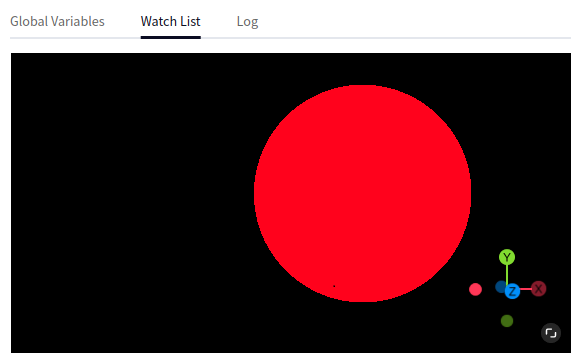
Calibration#
Calib Trans3D#
Introduction#
The 3D calibration transformation operator provides the function of transforming the pose in the camera coordinate system to the robot base coordinate system based on the hand-eye calibration result. The pose of the 3D point cloud is based on the camera coordinate system, which cannot be directly provided to the robot for task execution. It needs to be transformed to the robot base coordinate system through rigid body transformation.
Input#
- Input Pose
Type:
Pose3DPose3DListMeaning: List of poses to be processed
- File Input Type
Type:
StringMeaning: Configuration file path
Output#
- Trans Pose
Type:
Pose3DPose3DListMeaning: Result pose list
Parameters#
- Input File Path
Meaning: Configuration file input method
Range: Set from parameters, Set from input variables
- File Path
Meaning: Configuration file path
Read Calib File#
Introduction#
The calibration file reading operator provides the function of reading calibration files (hand-eye calibration files).
Input#
- Input File Path
Type:
StringMeaning: Configuration file path
Output#
- Hand Eye Pose
Type:
Pose3DMeaning: Hand-eye transformation pose
Parameters#
- File Input Type
Meaning: File input method
Range: Set from parameters, Set from input variables
- File Path
Meaning: File path
Location#
Coarse Match#
Introduction#
The coarse matching operator mainly provides two functions: one is to create a template based on the target point cloud (where the template creation is also divided into normal templates and tangent templates, the same as the 3D template matching operator); the second is to recognize the target in the scene based on the template and preliminarily estimate its pose. It can be simply understood as a split version of the “3D template matching” operator (3D template matching = coarse matching + fine matching).
Input#
- Input Cloud
Type:
PointCloudNormalDescription: Point cloud to be processed
Output#
- Coarse Pose
Type:
Pose3DListDescription: Pose of the matching result
- Debug3D
Type:
Debug3DDescription: 3D result image
Parameters#
- Model Path
Description: Path to the template file
- Angle Step Num
Description:
Range: [15, 100]
- Use Vote Ratio
Description: Ratio for filtering possible poses
Range: [1, 99]
- Model Sample Value
Description: Downsampling parameter to control voxel size when downsampling model (template) point cloud
Range: [0.5, 20]
- Scene Sample Value
Description: Downsampling parameter to control voxel size when downsampling scene point cloud
Range: [0.5, 20]
- Scene Sample Rate
Description: The larger the value, the slower the matching speed
Range: [1, 100]
- Max Match Num
Description: Control the number of matching results
Range: [1, 10]
- Match Result Use
Description: Usage rate of intermediate result poses
Range: [1, 100]
- Overlap Resolution
Description:
Range: [0.001, 10000]
- Intersect Overlap
Description:
Range: [0.0001, 1]
- Scene Model Overlap
Description:
Range: [0.0001, 1]
- Vote Weight
Description:
Range: [0, 1]
- OverlapWeight
Description:
Range: [0, 1]
Examples#
Input Image
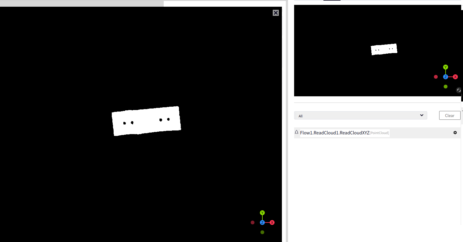
Output Image
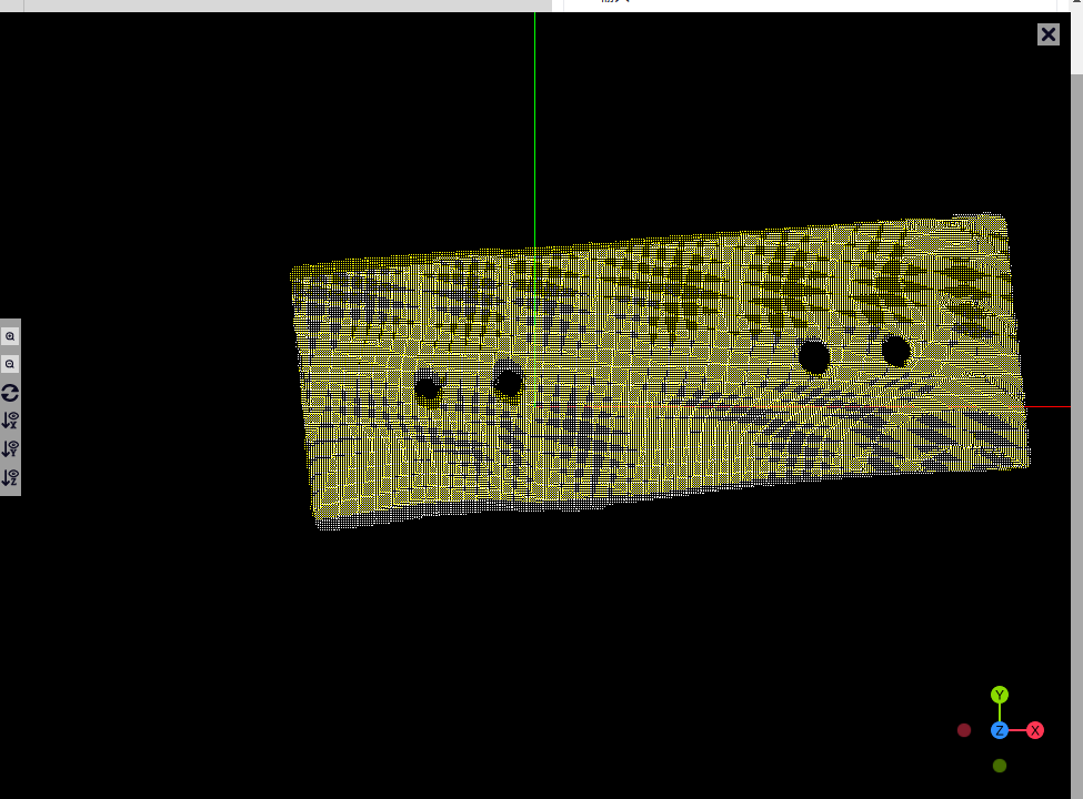
Fine Matching#
Introduction#
The fine matching operator mainly provides two functions: one is to create a template based on the target point cloud (where the template creation also includes normal templates and tangent templates, same as the 3D template matching operator); the second is to recognize the target in the scene based on the template and estimate its pose. It can be simply understood as a split version of the “3D template matching” operator (3D template matching = coarse matching + fine matching). It is usually used in conjunction with the coarse matching operator.
Input#
- Input Cloud
Type:
PointCloudNormalDescription: Point cloud to be processed
- Coarse Pose
Type:
Pose3DListDescription: Reference pose from matching
Output#
- Fine Pose
Type:
Pose3DListDescription: Pose of the matching result
- Debug3D
Type:
Debug3DDescription: 3D result image
Parameters#
- Model Path
Description: Path to the template file
- Fine Match Method
Description: Fine matching method
Range: Pyramid fine matching, classic fine matching
- Pyramid Fine Match - Prya-BoudingBox Expand Size
Description:
Range: [-1, 200]
- Pyramid Fine Match - Pyra-Sample Method
Description:
Range: Skip sampling, uniform sampling
- Pyramid Fine Match - Pyra-Model Sample Rate
Description: Downsampling parameter to control voxel size when downsampling model (template) point cloud
Range: [1, 100]
- Pyramid FineMatch - Pyra-Scene Sample Rate
Description: Downsampling parameter to control voxel size when downsampling scene point cloud
Range: [1, 100]
- Pyramid Fine Match - Pyra-Model Sample Value
Description: Downsampling parameter to control voxel size when downsampling model (template) point cloud
Range: [0.5, 20]
- Pyramid FineMatch - Pyra-Scene Sample Value
Description: Downsampling parameter to control voxel size when downsampling scene point cloud
Range: [0.5, 20]
- Pyramid FineMatch - Use Outiler Pairs
Description:
- Pyramid FineMatch - Iterative Tolerance Threshold
Description:
Range: [0.0001, 0.1]
- Pyramid FineMatch - Pyra-Max Iterations
Description:
Range: [5, 10000]
- Pyramid FineMatch - Pyra-Min Overlap
Description:
Range: [0.1, 0.99]
- Original FineMatch - Compute Method
Description:
Range: Point-to-surface, point-to-point
- Original FineMatch - Orig Bounding Box Expand Size
Description:
Range: [-1, 200]
- Original FineMatch - Orig Sample Method
Description:
Range: Skip sampling, uniform sampling
- Original FineMatch - Orig Model Sample Rate
Description: Downsampling parameter to control voxel size when downsampling model (template) point cloud
Range: [1, 100]
- Original FineMatch - Orig Scene Sample Rate
Description: Downsampling parameter to control voxel size when downsampling scene point cloud
Range: [1, 100]
- Original FineMatch - Orig Model Sample Value
Description: Downsampling parameter to control voxel size when downsampling model (template) point cloud
Range: [0.5, 20]
- Original FineMatch - Orig Scene Sample Value
Description: Downsampling parameter to control voxel size when downsampling scene point cloud
Range: [0.5, 20]
- Original FineMatch - Iterative Tolerance Threshold
Description:
Range: [0.0001, 0.1]
- OriginalFineMatch - OrigMaxIterations
Description:
Range: [5, 10000]
- Original FineMatch - Orig Min Overlap
Description:
Range: [0.1, 0.99]
Examples#
Algorithm |
Example: Input Image |
Example: Output Image |
|---|---|---|
Pyramid Fine Matching |
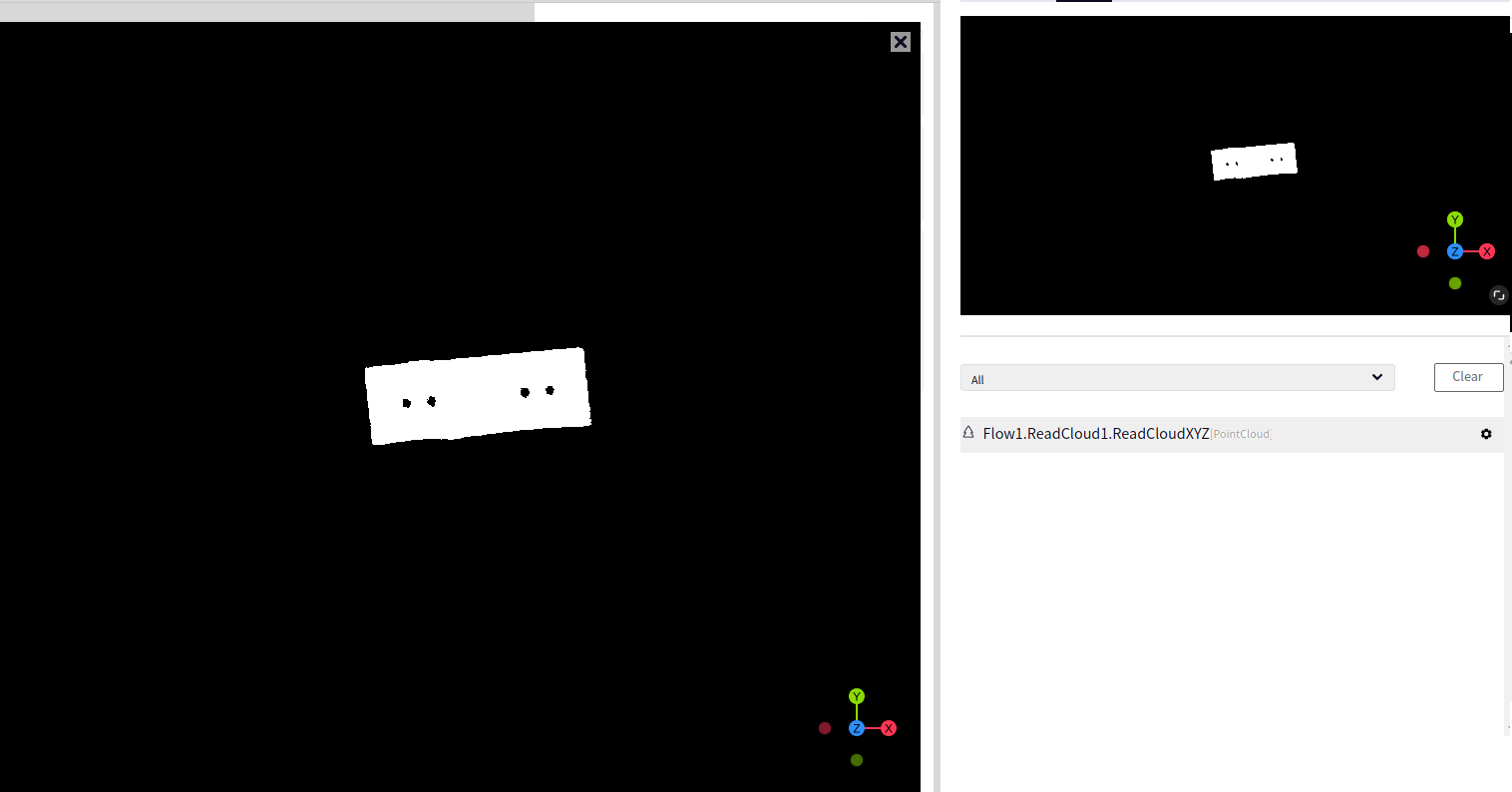
|
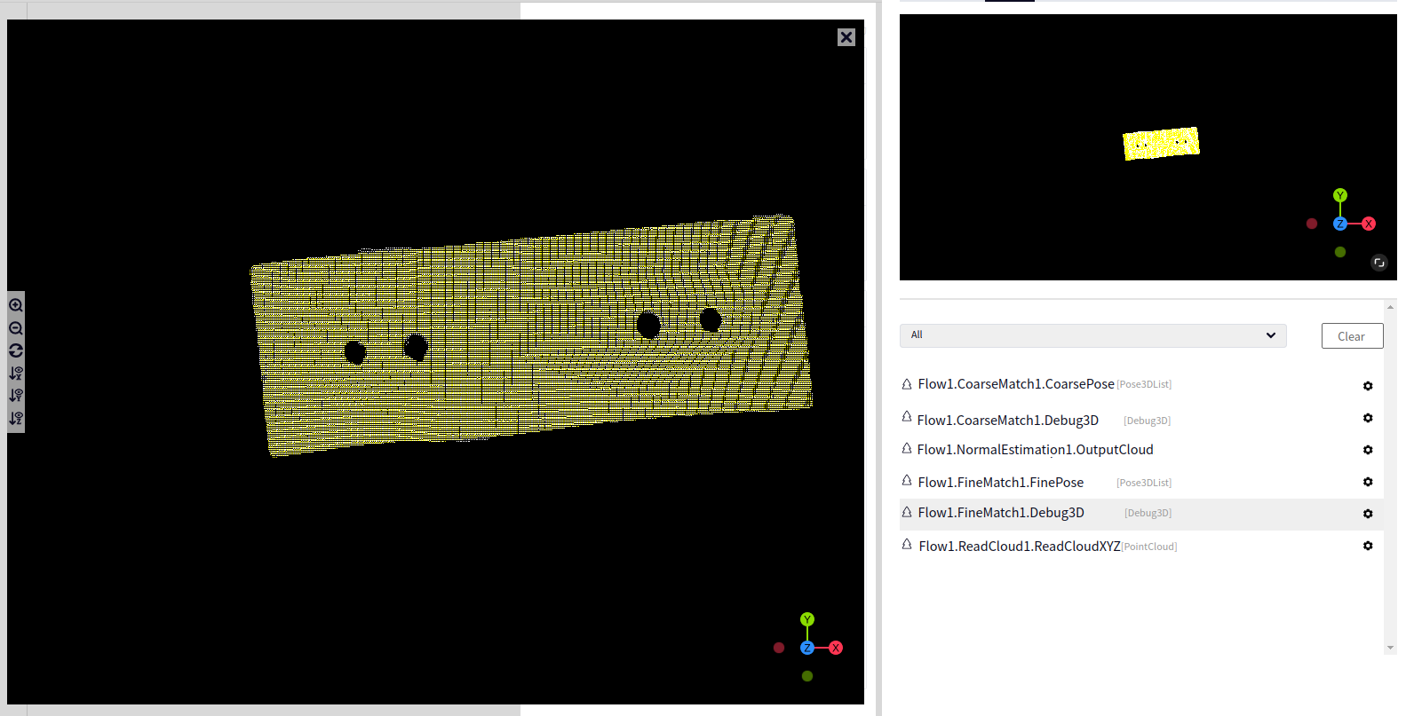
|
Original Fine Matching |
|
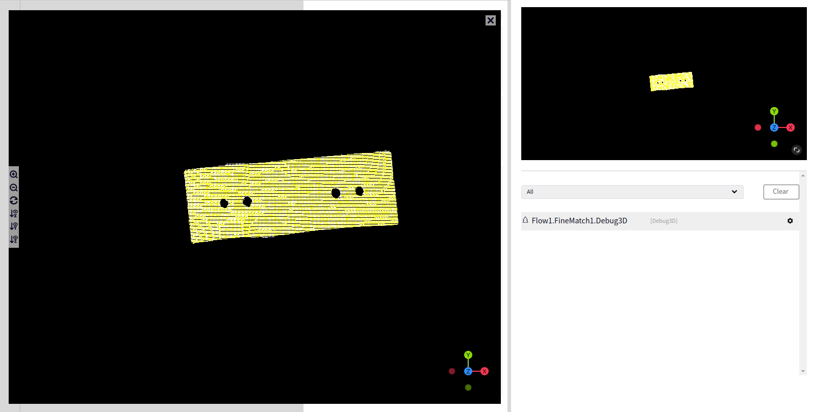
|
Deep Learning#
CloudObjDetectionFast#
Deep Learning Target Detection - Fast can be used to load pre-trained model files and perform inference on input images to achieve target detection functionality.
- Input Detect Image
Type:
ImageColorImageGrayMeaning: The image to be processed
- Output Labels
Type:
IntListMeaning: A collection of category labels for the detected targets
- Output Label Names
Type:
StringListMeaning: A collection of category labels name for the detected targets
- Output Score
Type:
DoubleListMeaning: A collection of category scores for the detected targets
- Output Bound Boxs
Type:
Rect2DListMeaning: A collection of bounding boxes for the detected targets
- Output Masks
Type:
RegionListMeaning: A collection of region masks for the bounding boxes of the detected targets
- Output Result Image
Type:
Debug2DMeaning: The result image of the target detection
- Model Path
Meaning: The path to the model file
- Threshold
Meaning: The score threshold for target detection
Range: [0.0, 1.0]
- Numbers
Meaning: The maximum number of targets to be displayed in target detection
Range: [0, 100]
Input Image
Output Image
CloudObjDetectionPerf#
Deep Learning Target Detection - Precision Detection can be used to load a trained model file and perform inference on an input image to achieve target detection functionality.
- Input Detect Image
Type:
ImageColorImageGrayMeaning: Image to be processed
- Output Labels
Type:
IntListMeaning: Collection of category labels from target detection results
- Output Label Names
Type:
StringListMeaning: Collection of category labels names from target detection results
- Output Score
Type:
DoubleListMeaning: Collection of category scores from target detection results
- Output Bound Boxs
Type:
Rect2DListMeaning: Collection of bounding boxes from target detection results
- Output Masks
Type:
RegionListMeaning: Collection of bounding box area masks from target detection results
- Output Result Image
Type:
Debug2DMeaning: Target detection result image
- Model Path
Meaning: Path where the model file is located
- Threshold
Meaning: Score threshold for target detection
Range: [0.0, 1.0]
- Numbers
Meaning: Maximum number of targets to display in target detection
Range: [0, 100]
Input Image
Output Image
CloudClassification#
Deep learning classification can be used to load trained model files and perform inference on input images to achieve classification.
- Input Detect Image
Type:
ImageColorImageGrayMeaning: The image to be processed
- Output Labels
Type:
StringListMeaning: The category labels of the classification results
- Output Score
Type:
DoubleListMeaning: The category scores of the classification results
- Output Result Image
Type:
Debug2DMeaning: The classification result image
- Model Path
Meaning: The path to the model file
Input Image
Output Image
CloudInstanceSegm#
Deep learning instance segmentation can be used to load pretrained model files and perform inference on input images to achieve instance segmentation.
- InputDetectImage
Type:
ImageColorImageGrayMeaning: The image to be processed
- Output Labels
Type:
IntListMeaning: The set of category labels resulting from instance segmentation
- Output Label Names
Type:
StringListMeaning: The set of category labels name resulting from instance segmentation
- Output Score
Type:
DoubleListMeaning: The set of category scores resulting from instance segmentation
- Output Bound Boxs
Type:
Rect2DListMeaning: The set of bounding boxes resulting from instance segmentation
- Output Masks
Type:
RegionListMeaning: The set of object masks within the bounding box resulting from instance segmentation
- Output Result Image
Type:
Debug2DMeaning: The result image of instance segmentation
- Model Path
Meaning: The path where the model file is located
- Threshold
Meaning: The score threshold for instance segmentation
Range: [0.0, 1.0]
- Numbers
Meaning: The maximum number of displayed instances for segmentation
Range: [0, 100]
- Pixel Threshold
Meaning: The score threshold for pixel points within the target mask in instance segmentation. This is a sensitive parameter; increasing it may cause incomplete mask display. The default is 0.1
Range: [0, 1.0]
Input Image
Output Image
AlgCloudMaskQuick#
Deep Learning Instance Segmentation (Fast) can be used to load trained model files and perform inference on input images locally using DUCOMind, providing information on the locations, bounding boxes, and categories of detected objects in the current image.
- Input Detect Image
Type:
ImageColorImageGrayMeaning: Image to be processed
- Output Labels
Type:
IntListMeaning: Collection of category labels from instance segmentation results
- Output Label Names
Type:
StringListMeaning: Collection of recognition result label names from instance segmentation (Fast)
- Output Score
Type:
DoubleListMeaning: Collection of category scores from instance segmentation results
- Output Bound Boxs
Type:
Rect2DListMeaning: Collection of bounding boxes from instance segmentation results
- Output Masks
Type:
RegionListMeaning: Collection of target masks within the bounding box from instance segmentation results
- Output Result Image
Type:
Debug2DMeaning: Result image from instance segmentation
- Model Path
Meaning: Path to the model file
- Threshold
Meaning: Score threshold for instance segmentation
Range: [0.0, 1.0]
- Numbers
Meaning: Maximum number of objects to display from instance segmentation
Range: [0, 100]
- Pixel Threshold
Meaning: Score threshold for pixels of target masks in instance segmentation; a sensitive parameter; increasing the parameter might cause incomplete mask display, default is 0.1
Range: [0, 1.0]
Input Image
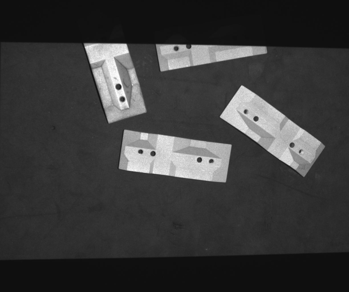
Output Image
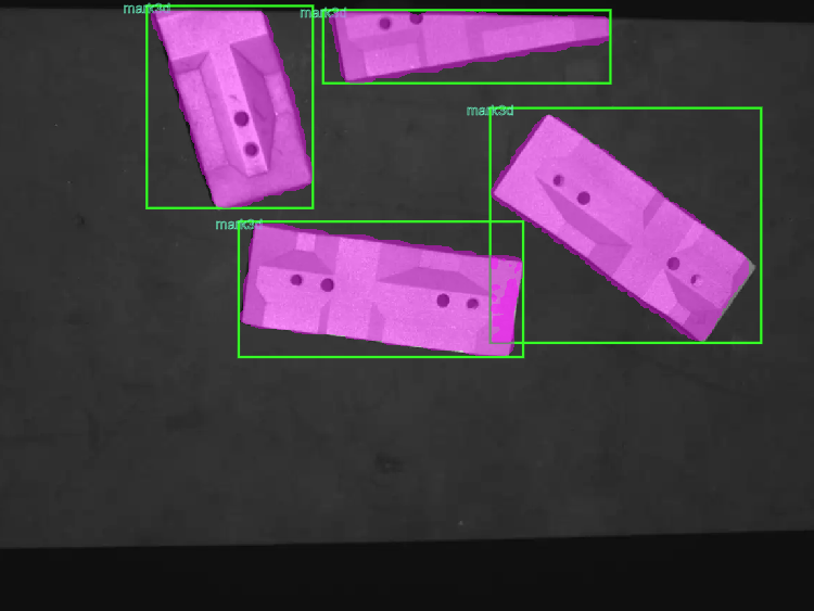
CloudRotationDetection#
Deep learning rotated box object detection can be used to load trained model files and perform inference on input images to achieve object detection functionality.
- InputDetectImage
Type:
ImageColorImageGrayDescription: Image to be processed
- Output Labels
Type:
IntListDescription: Set of category labels for rotated box detection results
- Output Label Names
Type:
StringListMeaning: Collection of category labels names from target detection results
- Output Score
Type:
DoubleListDescription: Set of category scores for rotated box detection results
- Output Rotation Bound Boxs
Type:
RotationRect2DlistDescription: Set of bounding boxes for rotated box detection results
- Output Masks
Type:
RegionListDescription: Set of bounding box region masks for rotated box detection results
- Output Result Image
Type:
Debug2DDescription: Result image of rotated box detection
- Model Path
Description: Path where the model file is located
- Threshold
Description: Score threshold for rotated box detection
Range: [0.0, 1.0]
- Numbers
Description: Maximum number of displayed objects for rotated box detection
Range: [0, 100]
Input Image
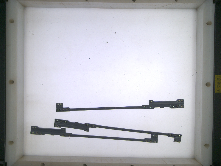
Output Image
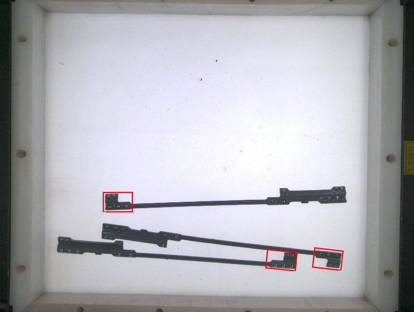
CloudKeypointCPMS#
Deep learning keypoint detection can be used to load trained model files and perform inference on input images to achieve keypoint detection functionality.
- Input Detect Image
Type:
ImageColorImageGrayMeaning: Image to be processed
- Output Labels
Type:
IntListMeaning: Collection of category labels for keypoint detection results
- Output Label Names
Type:
StringListMeaning: Collection of category labels names for keypoint detection results
- Output Locations
Type:
Vector2DListMeaning: Collection of keypoint positions for keypoint detection results
- Output Result Image
Type:
Debug2DMeaning: Keypoint detection result image
- Model Path
Meaning: Path to the model file
- Threshold
Meaning: Keypoint score threshold
Range: [0.0, 1.0]
- Numbers
Meaning: Maximum number of keypoints to display
Range: [0, 100]
- Gain
Meaning: Keypoint detection gain (default 2500, sensitive parameter requires tuning, for images with a lot of information try larger gain first)
Range: [100, 10000]
Input Image
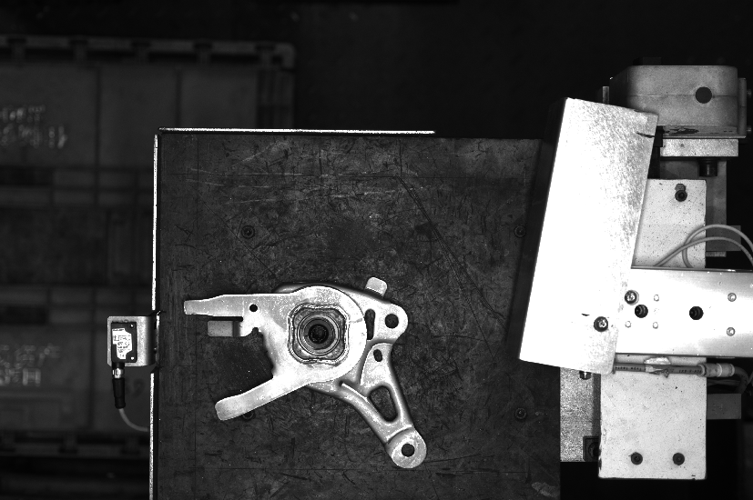
Output Image

Variables#
To String#
Convert various variables to string type.
- Input Value
Type:
Any VariableMeaning: Value to be processed
- String
Type:
StringMeaning: String
- Value Input Settings
Meaning: Method of inputting value
Range: From input settings, from parameter settings
- Serialization Configuration
Meaning: Separator flag
Range: Prefix, Suffix, Separator, List Prefix, List Suffix, List Separator
- Enter String
Meaning: Directly enter string
Input Image
Joint string#
Concatenate two strings into one string.
- String 1
Type:
StringMeaning: The string to be processed
- String 2
Type:
StringMeaning: The string to be processed
- Output String
Type:
StringMeaning: The output string
- Concatenation Configuration
Meaning: Delimiting marker
Range: Prefix, Suffix, Separator
Input Image
Value Write#
Assign one variable to another variable.
- Source Variable
Type:
any variableMeaning: Origin of the variable
- Target Variable
Type:
any variableMeaning: The variable to be assigned
Input Image
General Operators#
Script#
Introduction#
This script function manual is applicable for DUCO MIND programming.
The script uses Lua syntax, supporting native Lua syntax as well as some custom syntax and functions specific to this system.
Input#
Click on the script operator and open the template configuration to add or remove input variables. The following image shows how to open the template configuration.
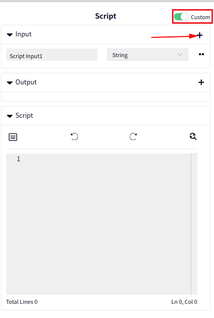
Click the + symbol indicated by the arrow in the image above to add an input. The default input type is String, and the default name is Script Input 1. Click the area indicated by the arrow in the image below to delete an input variable.
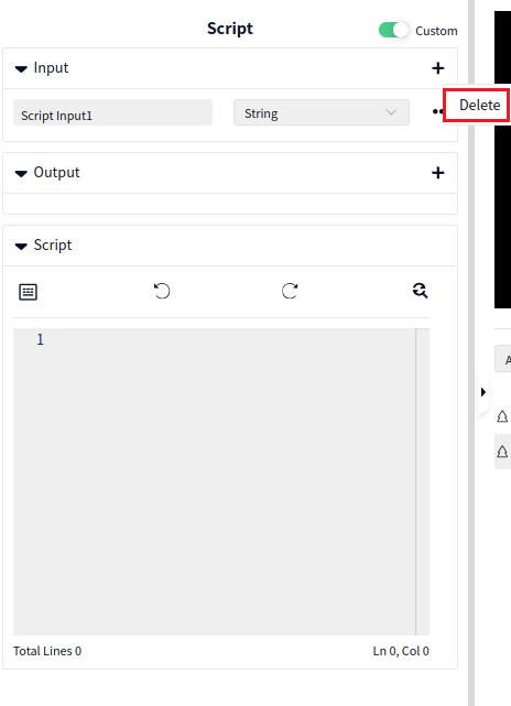
After adding or removing an input variable, close the template configuration switch. The result after closing is shown in the image below.
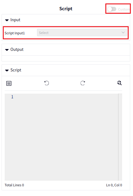
At this point, select a String type variable from the dropdown box after Script Input 1.
You can get the value of Script Input 1 using the following statement:
str1 = Script.get_value("Script Input1")
Output#
Click on the script operator and open the template configuration to add or remove output variables. The following image shows how to open the template configuration.
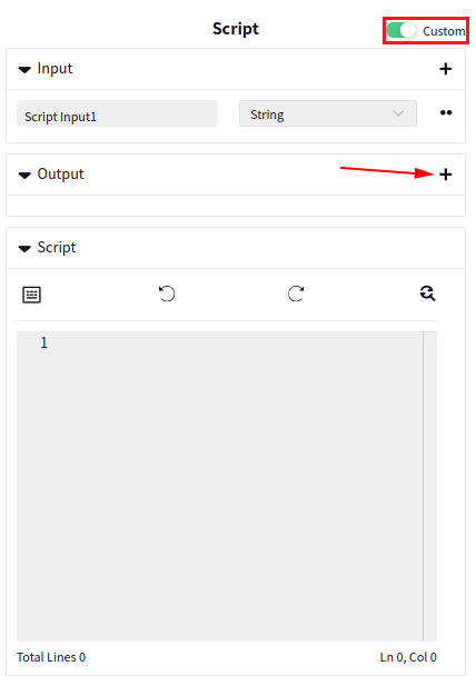
Click the + symbol indicated by the arrow in the image above to add an output. The default output type is String, and the output name is Script Output 1. Click the area indicated by the arrow in the image below to delete an output variable.
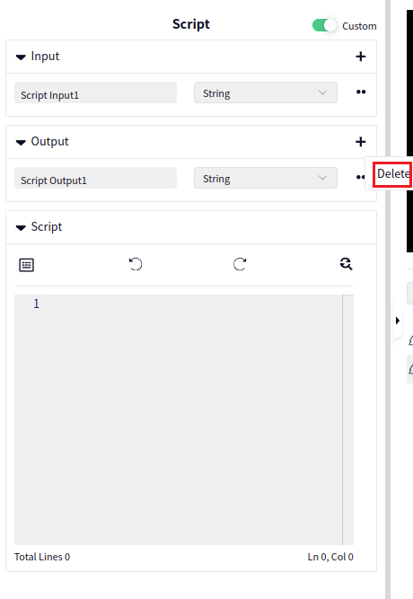
After adding or removing an output variable, close the template configuration switch. The result after closing is shown in the image below.
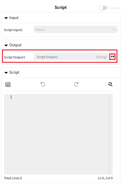
At this point, click the button indicated by the arrow after Script Output 1 to pop up the Monitor switch. Turning on the Monitor switch will add this output to the monitoring list.
To assign the value hello, world to Script Output 1, use the following statement:
Script.set_value("Script Output1", "hello, world")
Data Types and Variables#
Built-in Data Types#
Nil Type: nil, represents no valid value.
Arithmetic Type: The system’s built-in arithmetic type is double-precision floating-point number (number).
String Type: String, for example, “siasun robot”.
Boolean Type: Bool, such as true or false.
List Type (list): A table (array structure) that can contain other data types, for example, {1,2,3,4,5}, {“a”, “b”, “c”}.
Extended Data Types#
Pose3D#
Stores six Double type variables, for example: {1.1, 2.2, 3.3, 4.4, 5.5, 6.6}, usually used to represent the robot’s pose, for example:
my_pose3d=Pose3D.new({1.1, 2.2, 3.3, 4.4, 5.5, 6.6}) Defines a Pose3D type variable my_pose3d with the value {1.1, 2.2, 3.3, 4.4, 5.5, 6.6}
my_pose3d1=Script.get_value(my_pose3d):get() Reads the value from my_pose3d and assigns it to my_pose3d1
Script.set_value(my_pose3d2, my_pose3d1) Assigns the value of my_pose3d1 to my_pose3d2
Vector3D#
Stores three Double type variables, for example: {1.1, 2.2, 3.3}, for example:
my_vec3d=Vector3D.new({1.1, 2.2, 3.3}) Defines a Vector3D type variable my_vec3d with the value {1.1, 2.2, 3.3}
my_vec3d1=Script.get_value(my_vec3d):get() Reads the value from my_vec3d and assigns it to my_vec3d1
Script.set_value(my_vec3d2, my_vec3d1) Assigns the value of my_vec3d1 to my_vec3d2
System Constants#
A value like 42 is called a literal constant. Each literal constant corresponds to a data type. The form and value of the literal constant determine its data type and how it is used in the script. The system supports the following constants:
Basic Type Constants#
Arithmetic constants, true, false.
Arithmetic constants usually refer to double-precision floating-point constants. These constants can participate in relational operations, arithmetic operations, logical operations, and can be assigned to or initialize basic type variables. They can also be passed as arguments to functions.
In the system, true represents true.
In the system, false represents false.
String Constants#
String constants are collections of characters. String constants can be used to define string variables or passed as function parameters.
Variables#
Variables in the system are usually represented by a unique identifier (id). Variables must be defined before they can be used.
a =1.23 Variable assignment: the type of a is defined as double-precision floating-point, and a is initialized to 1.23.
b = true b is a Boolean variable, initialized to true.
c = false c is a Boolean variable, initialized to false.
s1= “siasun” s1 is a string variable, initialized to “siasun”.
s2= “SiasunCobot” s2 is a string variable, initialized to “SiasunCobot”.
s2=s1 s2 is assigned the value of s1, so s2 becomes “siasun”.
a1 = {} a1 is an empty list, with a length of 0.
a2={1.1, 2.2, 3.3, 4.4} a2 is a list of double-precision floating-point numbers, with a length of 4.
a3={ “a”, “b”, “c” } a3 is a list of strings, with a length of 3.
a4=a3 a4 is assigned the same reference as a3. Modifying a4 will also modify a3.
You can access specific elements using an index, with the index starting from 1. For example:
a2[1]=12
a3[2]= “siasun”
Expressions#
An expression in the system refers to an operation set that returns a value. It is a recursive definition.
Here, exp represents an expression, and op represents an operator.
Arithmetic Expressions#
The system supports four types of arithmetic operations: addition (+), subtraction (-), multiplication (*), and division (/). Arithmetic expressions return arithmetic constants.
Relational Expressions#
The system supports relational operations such as >, <, >=, <=, ==, ~=. Relational expressions return true or false.
Logical Expressions#
The system supports logical operators and, or, not.
exp1 and exp2: If exp1 is true and exp2 is true, the expression returns true; otherwise, it returns false.
exp1 or exp2: If exp1 is true or exp2 is true, the expression returns true; otherwise, it returns false.
not exp1: If exp1 is true, the expression returns false; otherwise, it returns true.
Assignment Expressions#
Variable name (id) = exp
The left-hand side of an assignment expression is a variable identifier. This expression is a valid assignment expression only if the variable has already been defined. If the variable has not been defined, it becomes a variable definition statement.
Function Call Expressions#
Function name (argument list)
Statements#
While Loop#
while (exp)
do
exp
…
end
Function Definition#
function fun( parameter list )
statement list
…
return exp
end
Example:
function fun1(a,b,c)
…
return a+b+c
end
Parameter types: Based on the actual passed parameters.
Return types: Based on the actual returned parameters.
A function can return multiple parameters, separated by ,. For example:
function fun1(a,b,c)
…
return a,b,c
end
Return Statement#
return exp
Tip
The return statement can only be used inside a function to return the result of the function’s operations.
The data type returned by the return statement determines the function’s return value. If the function does not contain a return statement, the function does not return any value.
Conditional Control Statements#
Form 1:#
if (exp)
then
…
elseif (exp)
then
…
else
…
end
Form 2:#
if (exp)
then
…
end
Form 3:#
if (exp)
then
…
else
…
end
Like most languages, the system supports if conditional control statements. When the judgment expression in if or elseif is true, the content in the statement block is executed.
Tip
The result of the control structure’s conditional expression can be any value. False and nil are false, while true and non-nil are true.
Note that 0 is considered true:
if (0)
then
print("0 is true")
end
Result: 0 is true
Goto Statement#
goto Label
:: Label::
Example:
a=1
::label:: print("----goto-----"")
if a<3 then
goto label
end
Break Statement#
Use the break statement to terminate a loop.
Example:
a=10
while( a<20 )
do
print("a=",a)
a=a+1
if(a>15) then
break
end
end
Functions#
Click the area indicated by the arrow in the image below to pop up the Script Add interface. This interface contains some commonly used functions. Clicking on a function name will display the function description.
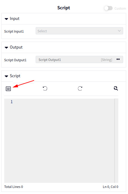
The Script Add interface is shown below. You can drag the current interface by holding the mouse at the top of the Script Add interface.
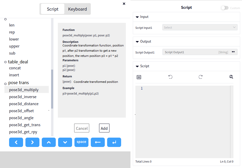
Clicking on a function name will display the function’s introduction page. The following image shows the introduction of the pose_multiply function:
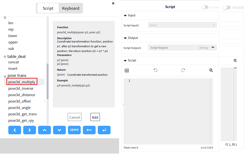
In the image above, double-clicking a function will directly add it to the script editor.
Assignment Functions#
set_value()
For example, to assign the value of a String type variable Str1 to Scipt Output 1:
set_value("Scipt Output1", Str1)
Value Retrieval Functions#
get_value()
For example, to retrieve the value of a String type Scipt Input 1:
valueStr=get_value("Scipt Input1")
For example, to retrieve the value of a Pose3D type Scipt Input 2:
valuePose=get_value("Scipt Input2")
Global Functions#
pose3d_multiplyorpose3d_trans: Multiply two poses to get a new pose.Parameter 1: Pose3D
Parameter 2: Pose3D
Return value: Pose3D
Example: pose1 = pose3d_multiply(pose2, pose3) or pose1 = pose3d_trans(pose2, pose3)
pose3d_inverseorpose3d_inv: Invert a pose.Parameter 1: Pose3D
Return value: Pose3D
Example: pose1 = pose3d_inverse(pose2)
pose3d_angle: Calculate the axis angle between two poses.Parameter 1: Pose3D
Parameter 2: Pose3D
Return value 1: Double
Return value 2: Vector3D
Example: angle, vec = pose3d_angle(pose1, pose2)
pose3d_distance: Calculate the spatial distance between two poses.Parameter 1: Pose3D
Parameter 2: Pose3D
Return value: Int
Example: distance = pose3d_distance(pose1, pose2)
pose3d_offset: Calculate the offset between two poses.Parameter 1: Pose3D
Parameter 2: Pose3D
Return value: Pose3D
Example: poseOff = pose3d_offset(pose1, pose2)
pose3d_get_trans: Extract the x, y, z values from a Pose3D into a Vector3D.Parameter: Pose3D
Return value: Vector3D
Example: vec = pose3d_get_trans(pose1)
pose3d_get_rpy: Extract the RX, RY, RZ values from a Pose3D into a Vector3D.Parameter: Pose3D
Return value: Vector3D
Example: vec = pose3d_get_rpy(pose1)
cross_product: Cross product of two vectors.Parameter 1: Vector3D
Parameter 2: Vector3D
Return value: Vector3D
Example: vec = cross_product(vec1, vec2)
rpy_to_axis_angle: Convert Euler angles to axis angles.Parameter 1: RPY
Return value: Double
Example: var = rpy_to_axis_angle(rpy)
axis_angle_to_rpy: Convert axis angles to Euler angles.Parameter 1: Vector3D
Parameter 2: Vector3D
Return value: RPY
Example: rpy1 = axis_angle_to_rpy(vec1, vec2)
vector3d_norm: Calculate the norm (magnitude) of a vector.Parameter: Vector3D
Return value: Float
Example: var = vector3d_norm(vec)
vector3d_normalized: Normalize a vector.Parameter: Vector3D
Return value: Vector3D
Example: vec1 = vector3d_normalized(vec2)
vector3d_cross: Cross product of two vectors.Parameter 1: Vector3D
Parameter 2: Vector3D
Return value: Vector3D
Example: vec = vector3d_cross(vec1, vec2)
vector3d_dot: Dot product of two vectors.Parameter 1: Vector3D
Parameter 2: Vector3D
Return value: Float
Example: dot = vector3d_dot(vec1, vec2)
rpy_to_rot: Convert Euler angles to a rotation matrix.Parameter: Vector3D
Return value 1: Vector3D
Return value 2: Vector3D
Return value 3: Vector3D
Example: vx, vy, vz = rpy_to_rot(vec)
rot_to_rpy: Convert a rotation matrix to Euler angles.Parameter 1: Vector3D
Parameter 2: Vector3D
Parameter 3: Vector3D
Return value: Vector3D
Example: vec = rot_to_rpy(vec1, vec2, vec3)
sleep: Pause the program for a specified time, in milliseconds.Parameter: Int
Example: sleep(500) means the program will pause for 500 milliseconds.
log: Print a log message.- Parameter 1: String, log level, supports the following four levels:
“debug”
“info”
“error”: Prints an error log.
“warn”
Parameter 2: String, log message content.
Example: log(“debug”, “hello, world”)
time: Calculate and return the current timestamp in milliseconds.Return value: Double, current timestamp.
Example: curTime = time()
Search#
Click the icon indicated by the arrow in the image below to pop up the search box. Enter the content you want to search for.
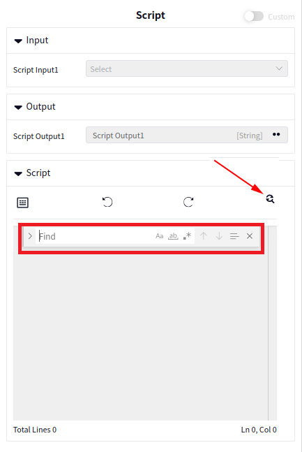
Sleep#
Make the program sleep for a period of time
- Sleep Time Unit
Description: The unit time of the sleep duration
Range: seconds, milliseconds
- Sleep Time
Description: The duration of the sleep
Range: [0, 2147483647]
Arrays#
Clear Array#
Clear the contents of an array.
- Input Array
Type:
Any arrayMeaning: the array to be processed
Add Array Value#
This module get a value from an array.
- Input Array
Type:
any arrayDescription: The array to be processed
- Array Element Value
Type:
any arrayDescription: The value of the retrieved element
- Index
Description: The index of the element to retrieve
Range: [1, 2147483647]
Create Array#
Clear an existing array.
- Output Array
Type:
Any ArrayMeaning: Newly created array
- Array Type
Meaning: Type of the newly created array
Range: BoolList, Circle2DList, DoubleList, Edge2DList, ImageColorList, ImageGrayList, IntList, Line2DList, LineSegment2DList, Point2DList, PointCloudList, PointCloudNormalList, Polygon2DList, Pose2DList, Pose3DList, PropertyTypeList, Rect2DList, RegionList, Ring2DList, RotatedRect2DList, Size2DList, StringList, Text2DList, Vector2DList, Vector3DList, Vector4DList
Delete Array Value#
Delete a specific value from an array.
- Input Array
Type:
any arrayMeaning: The array to be processed
- Index of Value to Delete
Meaning: The index of the value to be deleted
Range: [1, 2147483647]
Add Array Element#
Add an element to an array.
- Input Array
Type:
Any ArrayMeaning: The array to be processed
- Element to Add
Type:
Any Matching ElementMeaning: The element to be added
Logic Operators#
Parallel#
Customizable parallel execution logic for branches.
Click the + sign in the upper right corner to add branches. The toggle switch controls branch enablement.
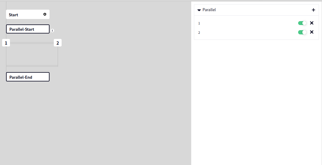
Switch#
Customizable logic for branch selection.
- Type
Definition: The type of the element to be evaluated
Range: Int, Double, Bool, String
- Variable Description Name
Definition: The specific value to be evaluated
- Condition
Definition: Evaluation condition
Click the + sign in the top right corner to add branches, and use the toggle switch to enable or disable branches.
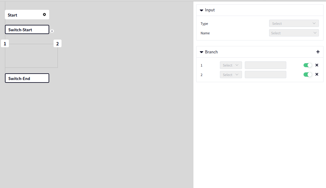
Loop#
The function of looping based on conditions.
- Type
Meaning: Select the type of element to be judged
Range: Int, Double, Bool, String
- Conditional Variable
Meaning: The specific value to be judged
- Loop Condition
Meaning: The condition for loop judgment
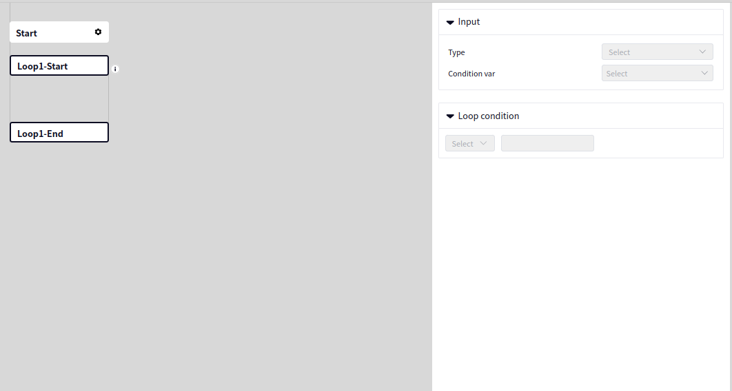
Foreach#
Functionality to traverse elements in an array.
- Input
Type:
Any arrayMeaning: The array to process
- Output
Type:
Corresponding elementMeaning: The element that is output
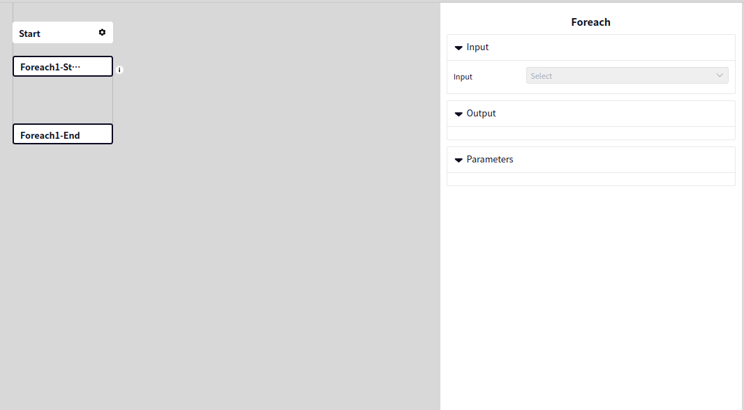
Camera#
Camera Capture#
The camera capture operator can call a connected camera in DucoMimd to take a picture. When taking pictures, functions such as retrying upon failure and reconnecting upon failure can be set.
- Input Camera
Type:
CameraMeaning: The name of the connected camera
- Output Result
Type:
BoolMeaning: Whether the camera capture was successful
- Auto Reconnect
Auto Reconnect: Whether to enable the camera’s auto reconnect feature
Reconnect Attempts: The number of times to automatically reconnect when the camera is not connected
Reconnect Interval: The time interval between each connection attempt
- Retry Capture on Failure
Auto Capture: Whether to enable the camera’s auto retry capture feature
Retry Attempts: The number of times to automatically retry capturing when the camera fails to capture
Retry Interval: The time interval between each retry capture attempt
- Camera Type
Meaning: Parameters that can be set on the camera before using the camera capture operator
Tip
When setting the camera parameters using the camera capture operator, if the selected camera type does not match the current camera type, the output result of the operator will be false.
The camera parameters displayed in the camera capture operator are the default parameter sets of the camera and cannot be dynamically updated according to the specific camera instance’s parameters. However, after changing the parameters in the camera capture operator, the parameters of the specific camera instance will be updated.
Debugging#
2D Debug#
The 2D debug operator can input a Debug2D operator and draw specific parameters into it, such as images, lines, coordinate axes, and points.
- Input Debug2D
Type:
Debug2DDefinition: Input data of type Debug2D, subsequent drawings will be performed on this data.
- Input Vector2D
Type:
Vector2DVector2DListDefinition: Data of types Vector2D and Vector2DList, representing the drawing of points.
- Input Pose2D
Type:
Pose2DPose2DListDefinition: Data of types Pose2D and Pose2DList, representing the drawing of coordinate axes.
- Input Region
Type:
RegionRegionListDefinition: Data of types Region and RegionList, representing the drawing of Regions.
- Input String
Type:
StringStringListDefinition: Data of types String and StringList, representing the drawing of text.
- Input Image
Type:
ImageColorImageGrayDefinition: Data of types ImageColor and ImageGray, representing the drawing of images.
- Drawing type
Vector2D: Requires input of data of type
Vector2DorVector2DList, representing drawing points at one or several specific coordinates.Pose2D: Requires input of data of type
Pose2DorPose2DList, representing drawing coordinate axes at one or several specific coordinates.Region: Requires input of data of type
RegionorRegionList, representing drawing one or multiple Regions.String: Requires input of data of type
String, representing drawing text at coordinate points.String_Pose2D: Requires input of data of type
String/StringListandPose2D/Pose2DList, representing drawing text at specific coordinates.Image: Requires input of data of type
ImageColororImageGray, representing drawing images.
- Color and thickness configuration
Panel color: The color drawn on the panel, optional
Green,Red,Black,Blue,White.Fill color: The fill color, optional
Green,Red,Black,Blue,White.Thickness: The thickness of the line or point.
Panel switch: Whether to enable panel color.
Fill switch: Whether to enable fill color.
Line type: Can choose whether to draw the line as
SolidorDashed.
- Thickness and size configuration
Thickness: The thickness of the drawing line.
Size: The size of the drawing points.
- Color configuration
Color: The color of the drawing panel.
Thickness: The thickness of the drawing line.
- String and Pose2D configuration
Color: The color of the drawing text.
Thickness: The size of the drawing text.
3D Debug#
The 3D Debug operator can input a Debug3D operator and draw specific parameters into it, such as point clouds, coordinate axes, and dots.
- Input Debug3D
Type:
Debug3DMeaning: Input data of type Debug3D, subsequent drawings will be performed on this data.
- Input Vector3D
Type:
Vector3DVector3DListMeaning: Data of type Vector3D and Vector3DList, indicating that dots are to be drawn on Debug3D.
- Input Pose3D
Type:
Pose3DPose3DListMeaning: Data of type Pose3D and Pose3DList, indicating that coordinate axes are to be drawn on Debug3D.
- Input PointCloud
Type:
PointCloudXYZPointCloudNormalMeaning: Data of type PointCloudXYZ and PointCloudNormal, indicating that point cloud data is to be drawn on Debug3D.
- Drawing Type
Vector3D: At this time, you need to input data of type
Vector3DorVector3DList, indicating that dots are drawn at one or several specific coordinates.Pose3D: At this time, you need to input data of type
Pose3DorPose3DList, indicating that coordinate axes are drawn at one or several specific coordinates.PointCloud: At this time, you need to input data of type
PointCloudorPointCloudNormal, indicating that point cloud is drawn.
- Color and Thickness Configuration
Panel color: The color drawn on the panel, optional values
Green,Red,Black,Blue,White.Thickness: The thickness of the lines or dots.
Panel switch: Whether to enable panel color.
Fill switch: Whether to enable fill color.
- Length and Thickness Configuration
Thickness: The thickness of the lines drawn.
Length: The length of the lines drawn.