


Application Manual#
DM-Mark3D Mark Block Positioning Application#
Create a New Project#
Open the DUCOMIND webpage. If the controller’s IP address is known, you can open the DUCOMIND webpage on another laptop or computer, provided that the device’s network is set to the same subnet as the controller’s IP. For example, if the controller’s IP is 192.168.3.10, you can access it by visiting 192.168.3.10:7300.
For more details, see: Software Operation Guide->Project Management->Create New Project
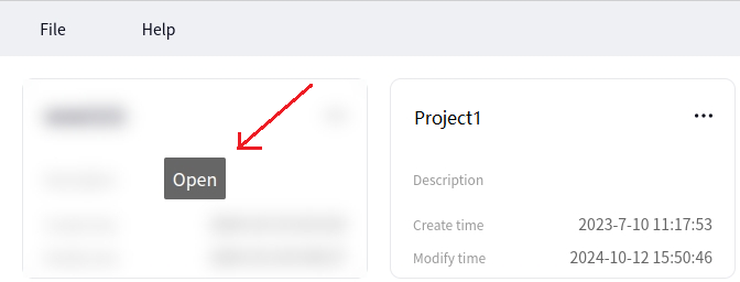
After opening the DUCOMIND webpage, if a project has already been created, you can directly click on the project name, and an Open option will appear. Click Open to open the corresponding project. The image below shows the effect after clicking the first project.
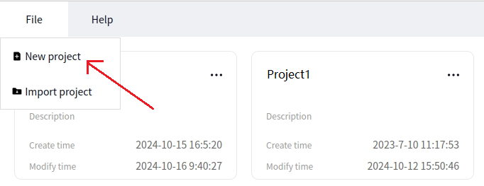
If you want to create a new project, just click New Project, as shown below.
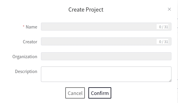
After clicking New Project, the following interface will pop up. Enter the relevant information to proceed.
Camera#
For more details, refer to: Software Operation Guide->Camera Management->Create New Camera and Software Operation Guide->Camera Management->Camera Configuration->Zhiwei Camera
Hardware Introduction#
Vision Tooling Introduction#
Vision Option Package List#
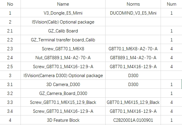
Calibration Board Installation Diagram (Calibration Board in Hand)#
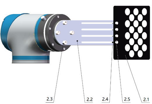
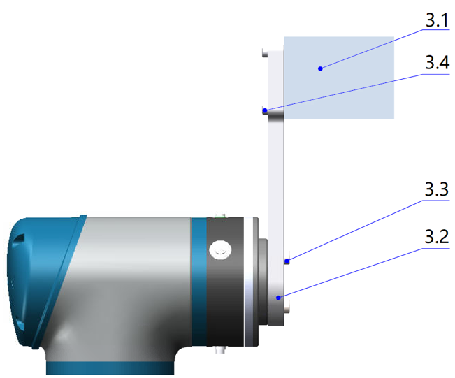
3D Camera Installation Diagram (Camera in Hand)#
Camera Network Cable Connection#
Insert the camera network cable into the controller’s network port. Ensure that the inserted port is set to Local Link Only. The method to set a controller’s network port to Local Link Only is as follows:
Method 1
Open a terminal. If directly using the teach pendant display, press Ctrl+Alt+F2/F3/F4 to open a terminal.
The current controller has three network ports, named enp1s0, enp2s0, and enp3s0.
3. To set the enp1s0 port to Local Link Only, the command is:
sudo ifconfig network_port_name 169.254.7.12 broadcast 169.254.255.255 netmask 255.255.0.0
Tip
Typically, the middle port is enp3s0, the one near the HDMI port is enp2s0, and the other is enp1s0. The factory IPs are pre-configured, so you can connect the camera network cable to the enp1s0 port.
Method 2
Open the management software (DucoManager) interface and click Network Configuration.
After clicking Network Configuration, you will see three network statuses: LAN1, LAN2, and LAN3. These three ports correspond to LAN1, LAN2, and LAN3 on the controller.
Select either LAN2 or LAN3, click settings, and set the network port to Local Link Only.
Insert the camera network cable into the port set to Local Link Only.
Camera Power Cable Connection#
The camera power supply must meet the voltage specification of 24V and a current of 2A. The following image shows the standard camera power adapter information.
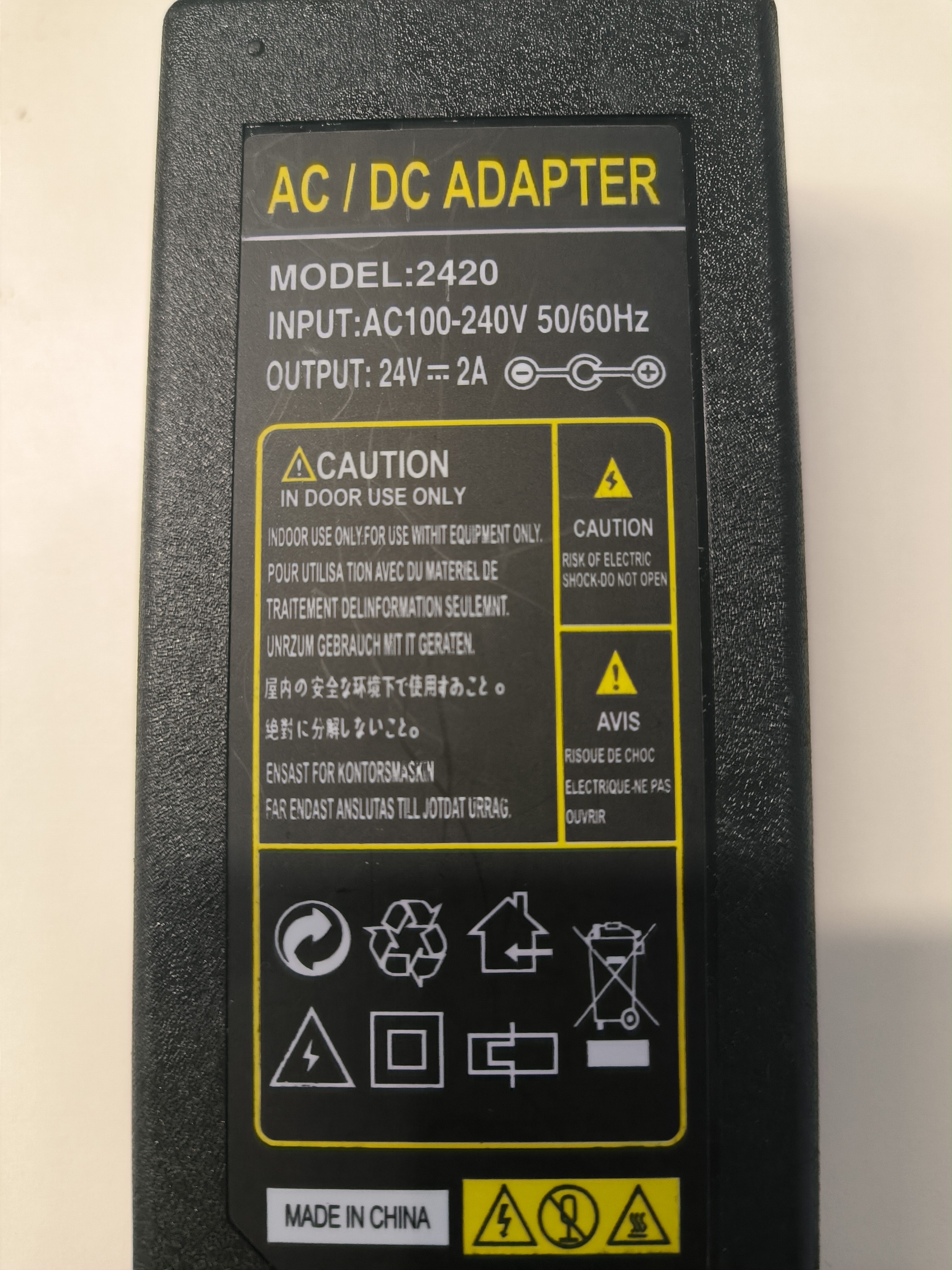
Caution
After connecting the camera power for the first time, the camera lens will light up and display the Logo. The Logo will disappear after about 10-20 seconds. If the camera lens does not light up or the Logo remains displayed after powering on, check the power wiring.
Create a New Camera#
Open the newly created project or an existing project, and create a CameraZhiWei.
As shown below, click the arrow to pop up the Create Camera interface. Select CameraZhiWei as the camera model.
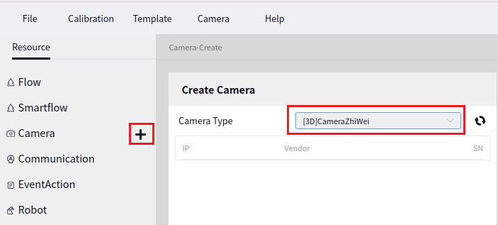
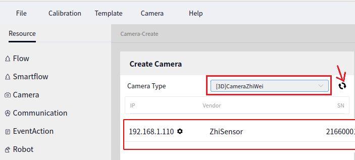
After selecting the camera model, click the scan button indicated by the arrow below to scan for the CameraZhiWei currently connected to the device.
Tip
The result in the image above shows a locally connected Zhiwei Camera after scanning. After clicking scan, wait a few seconds for the result.
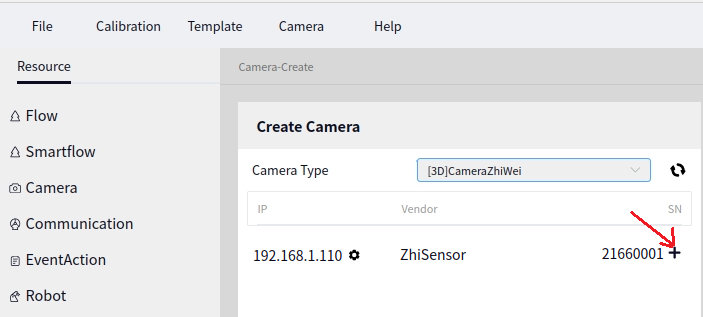
Once the ZhiWei Camera is detected, click the + sign next to the camera information to create a new camera, as shown below:
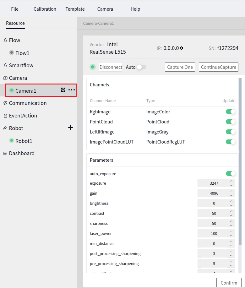
After creating the camera, the first camera’s default name is Camera1. Click Camera1 to bring up the camera configuration interface, as shown below:
Connect the Camera#
Click the Connect button, and the system will attempt to connect to the Zhiwei Camera. Usually, the connection succeeds after waiting a few seconds. Once connected, the Connect button will turn into a Disconnect button.
Tip
The ZhiWei Camera is a POE interface camera. After connecting to the device, the network port must be set to Local Link Only to connect successfully. (If the camera’s IP is known in advance, setting the network to the same subnet as the camera will also work.)
If the camera fails to connect, a pop-up error window will appear. In this case, check the network port configuration and ensure the network cable and camera are intact. Insufficient power supply could also be the cause.
Parameter Configuration#
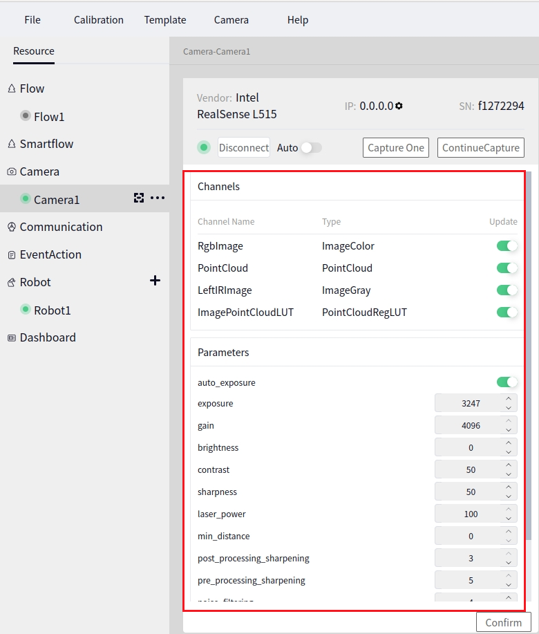
The following image shows the parameter configuration interface for the Zhiwei Camera.
Tip
The parameters we often configure are IR Exposure and Multiple Exposure Count.
IR Exposure: Adjust this parameter if the camera’s image is too bright or too dark.
Multiple Exposure Count: The number of times the camera flashes (default is once; this parameter can be set to 3).
Click the confirm button after setting to apply the changes.
Robot#
For more details, refer to: Software Operation Guide->Robot Management->Create New Robot
Create a New Robot#
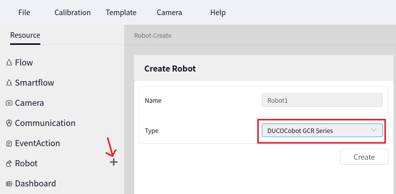
Click the arrow below to pop up the new robot interface.
Tip
The supported robot models are ducocore_gcr10 and ducocore_gcr5.
Click the Create button to create a new robot.
Connect the Robot#
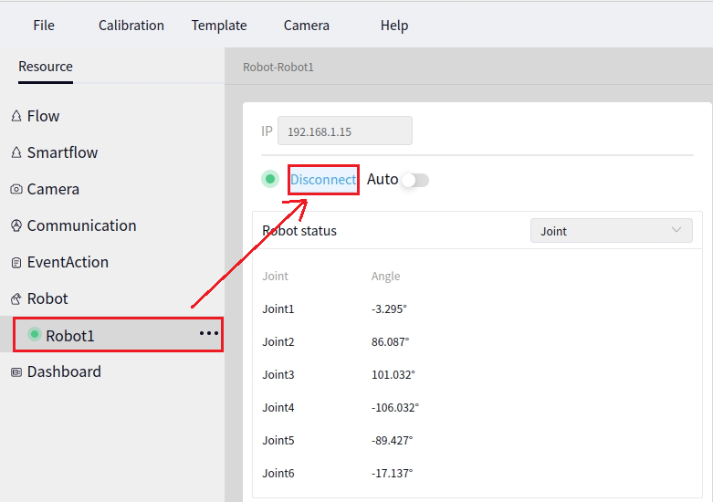
Click the newly created robot name to bring up the robot configuration interface. Enter the robot’s IP address and click the Connect button to connect the robot. Once connected, the Connect button will turn into Disconnect, and the circle in front of the connection status will turn green, as shown below.
3D Hand-Eye Calibration#
There are two types of calibration objects for 3D hand-eye calibration: Calibration Sphere and Calibration Board. Choose one to perform the calibration.
Method One (3D Calibration Sphere)#
For more details, refer to: Software Operation Guide->Tools->3D Hand-Eye Calibration->Calibration Sphere
Entry Point#
As shown below, select Calibration->Calibration-3D.
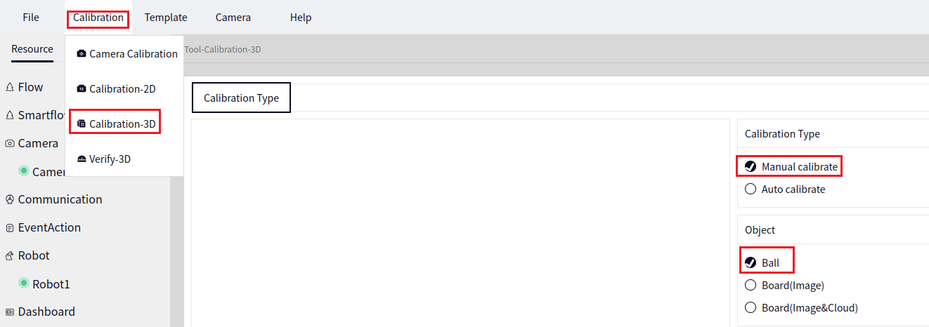
In the image above, select Calibration Type as Manual Calibration and Object as Ball, then click Next to proceed to the following interface.
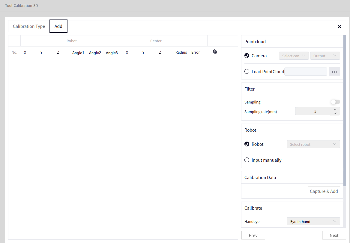
- In the image above:
- Point Cloud Data (Choose one of two; select Camera Data here)
Camera Data: Select the point cloud data of the locally connected camera. At this point, choose the camera just connected, such as Camera1, then select Point Cloud Data or pointcloud in Select Output.
Load Point Cloud: Load a point cloud in ply format from a local path.
- Point Cloud Filtering (No need to enable it here)
Point Cloud Sampling: Indicates point cloud downsampling. When the switch is toggled to the right, it is enabled; to the left, it is disabled. The image above shows it disabled, so leave it as is.
Sampling Accuracy: The higher the sampling accuracy, the lower the quality of the output point cloud.
- Robot Data (Choose one of two; select Robot here)
Robot: Select the locally connected robot. At this point, choose the robot just connected, such as Robot1.
Manual Input: Manually input the robot’s pose each time the robot is moved. After successfully adding data, the robot data will appear under the Robot section in the data bar on the left side of the interface.
Take Photos and Add Data#
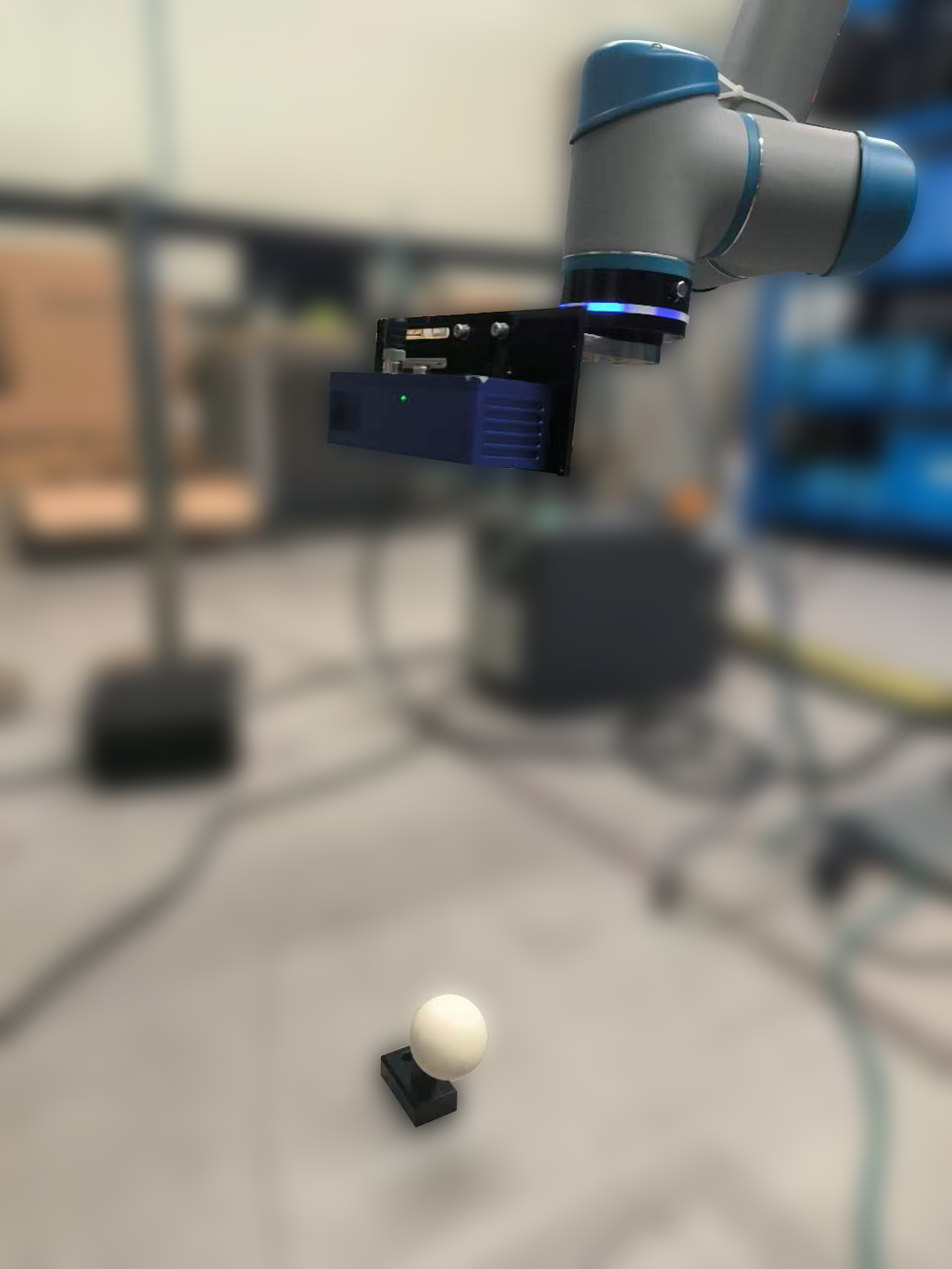
Once the parameters are set, place the calibration sphere directly below the camera. It is best if the camera is parallel to the ground, as shown below.
After setting the parameters, click the Take Photo and Add Data button. After clicking, it will enter the Calibration Sphere Recognition interface, as shown below.
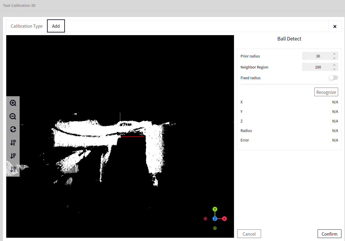
- In the image above:
The left area is the Point Cloud Browser, displaying the Point Cloud of the Calibration Sphere. At this point, you need to click the center of the calibration sphere (approximately) with the mouse.
Prior Radius: The current radius of the calibration sphere.
Neighborhood Range: Indicates the number of points selected around the center of the sphere during calibration.
Fixed Radius: The image above shows that the fixed radius is enabled (default is off). The switch to the right indicates it is enabled. If disabled, the prior radius will be optimized. If enabled, the prior radius value will be used to calculate the sphere center coordinates.
Calibration Sphere Recognition#
Click the center of the sphere’s point cloud on the left side of the image above, and the current xyz point will be displayed. Then click Recognize. The result after successful recognition is shown below.
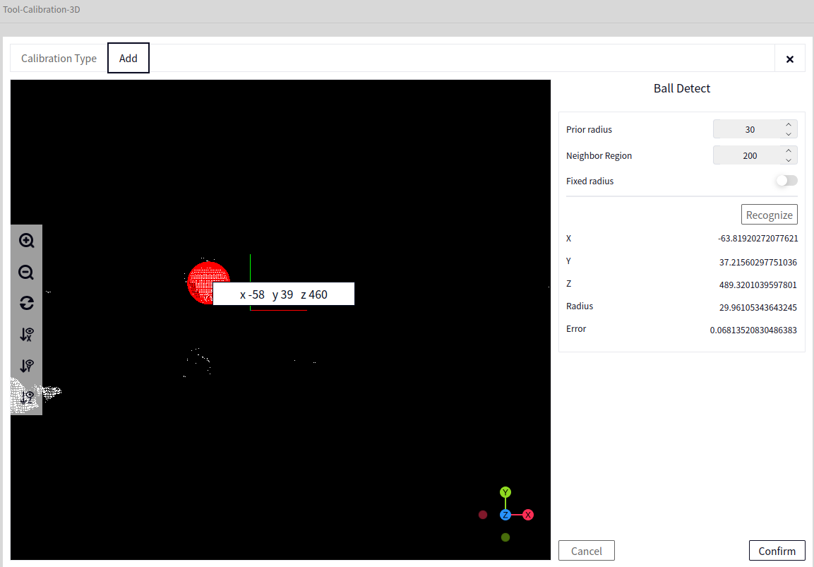
Tip
When the point cloud data of the sphere captured at a position is good and can be recognized, it is best to record the current position on the DUCOCORE side for use in template creation later.
The image above indicates successful recognition. At this point, click Confirm to add a data entry. After clicking Confirm, it returns to the previous interface, as shown below.
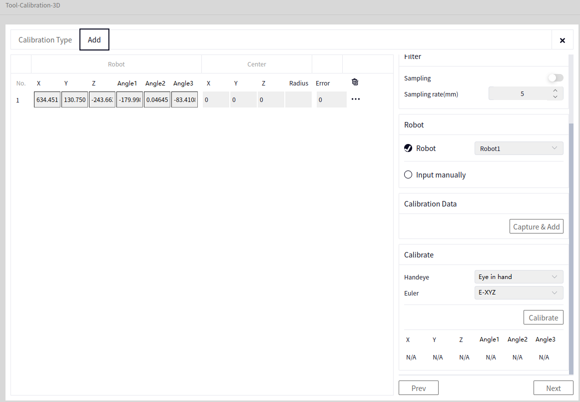
The image above shows that 1 data entry has been successfully added. Now, move the robot to different positions and perform Take Photo and Add Data -> Recognize.
The key is to place the camera directly above, to the upper left, upper right, front, and back of the sphere, and at three different heights in these directions, for a total of 15 positions. Ensure that after moving, the camera can capture the calibration sphere. The camera’s positions are approximately as shown in the following series of images:
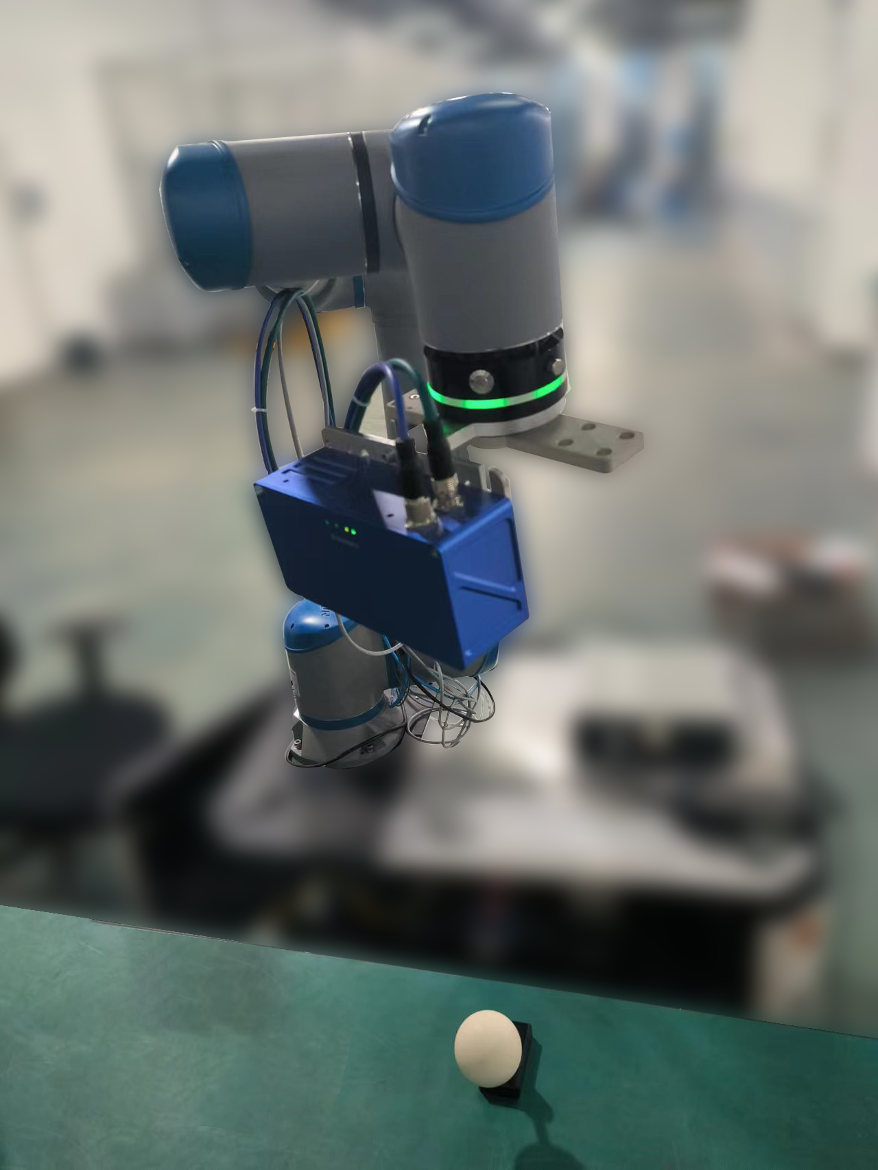
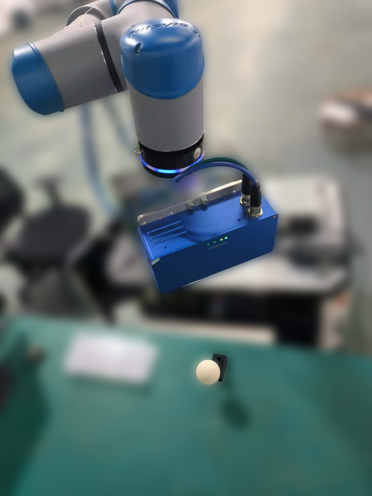
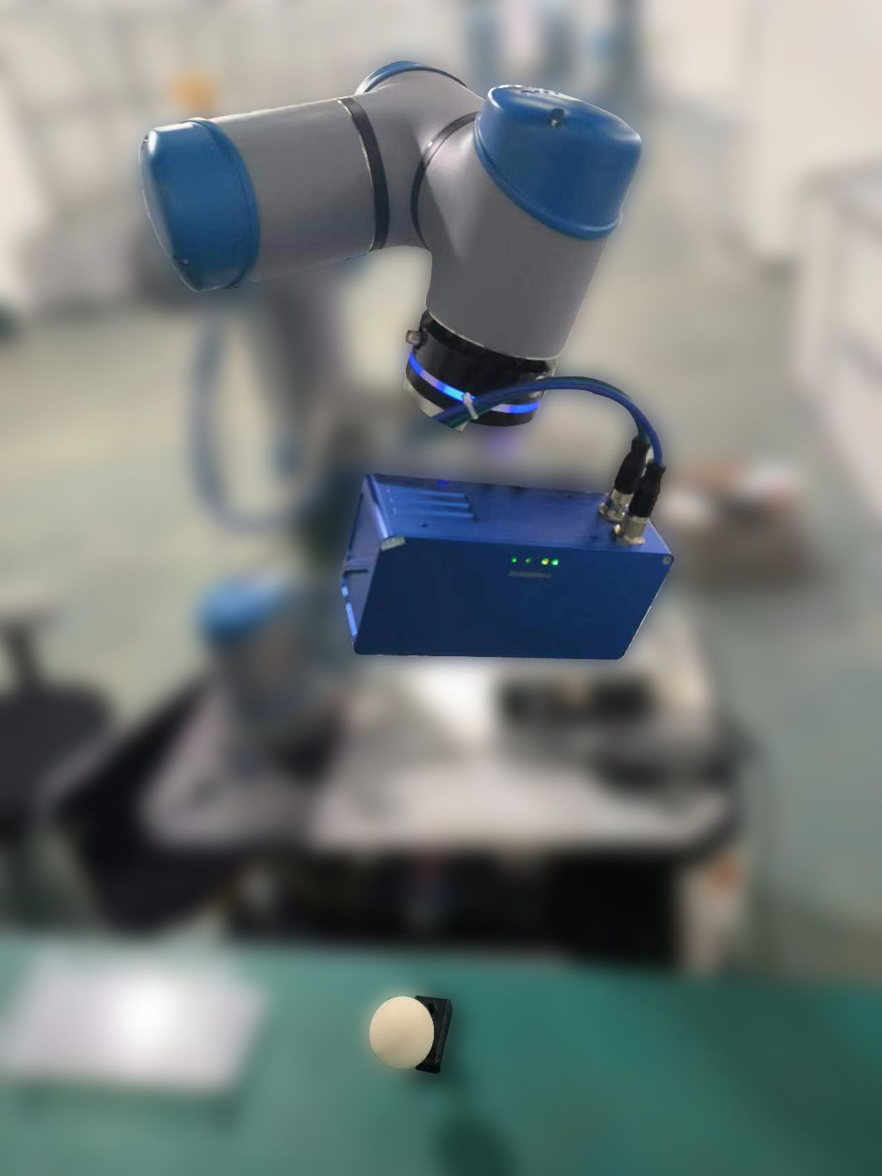
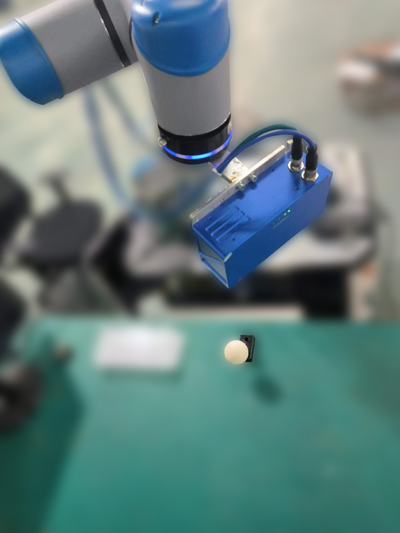
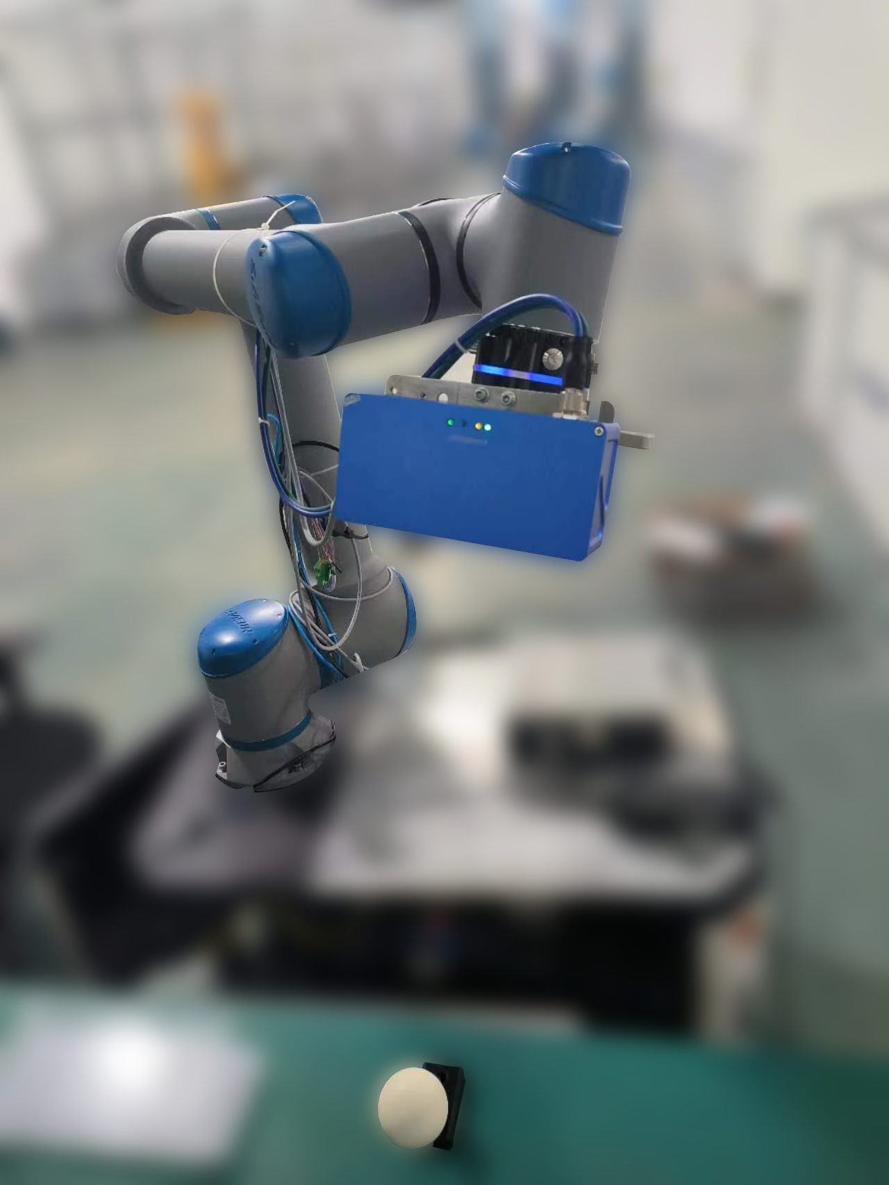
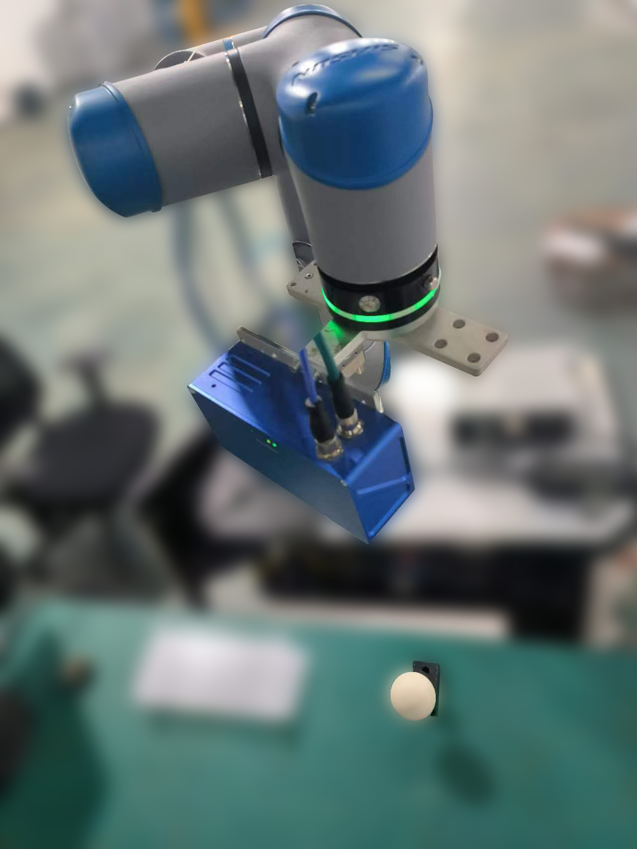
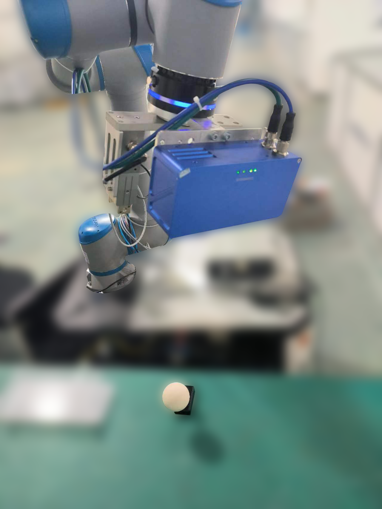
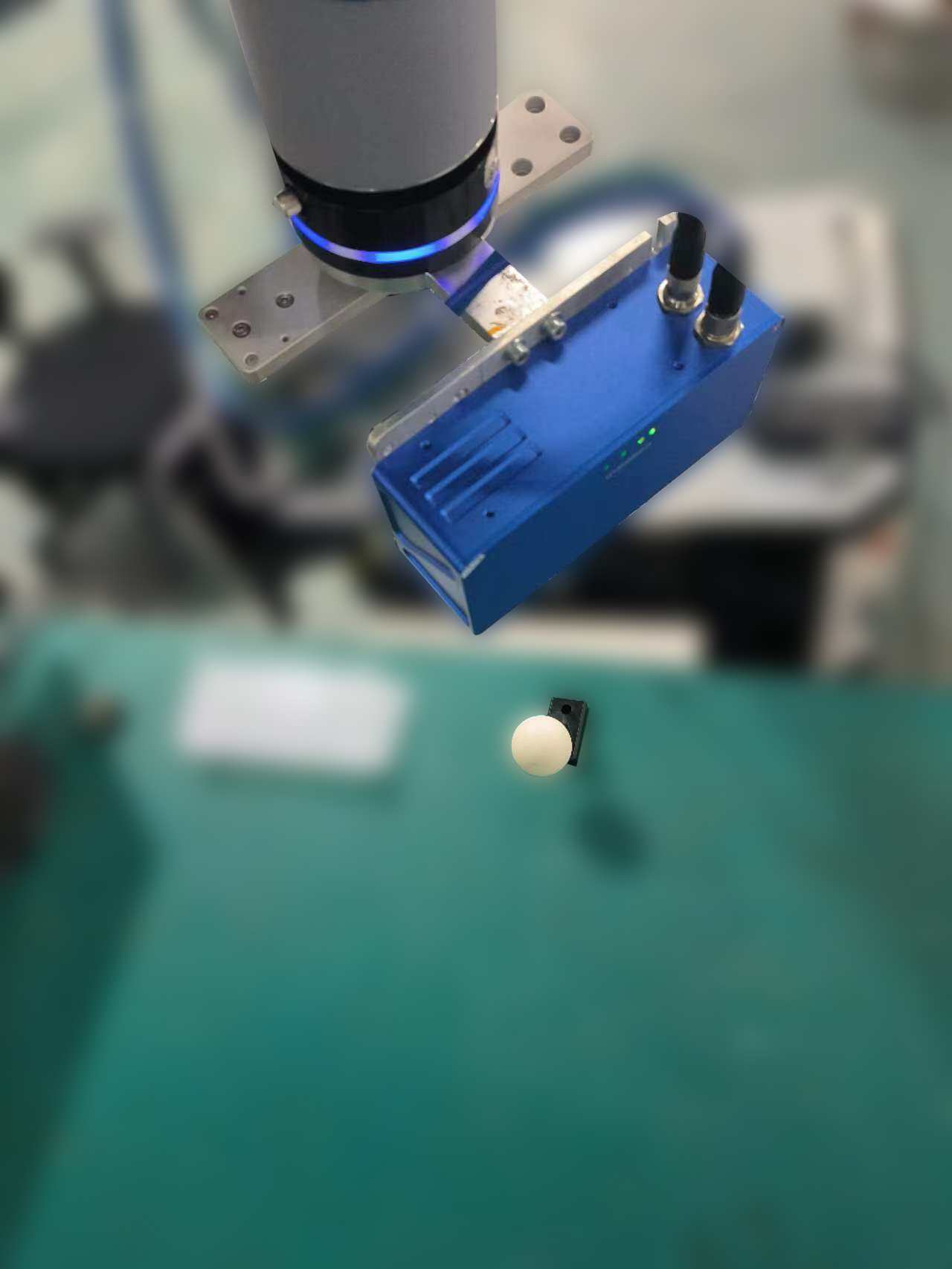
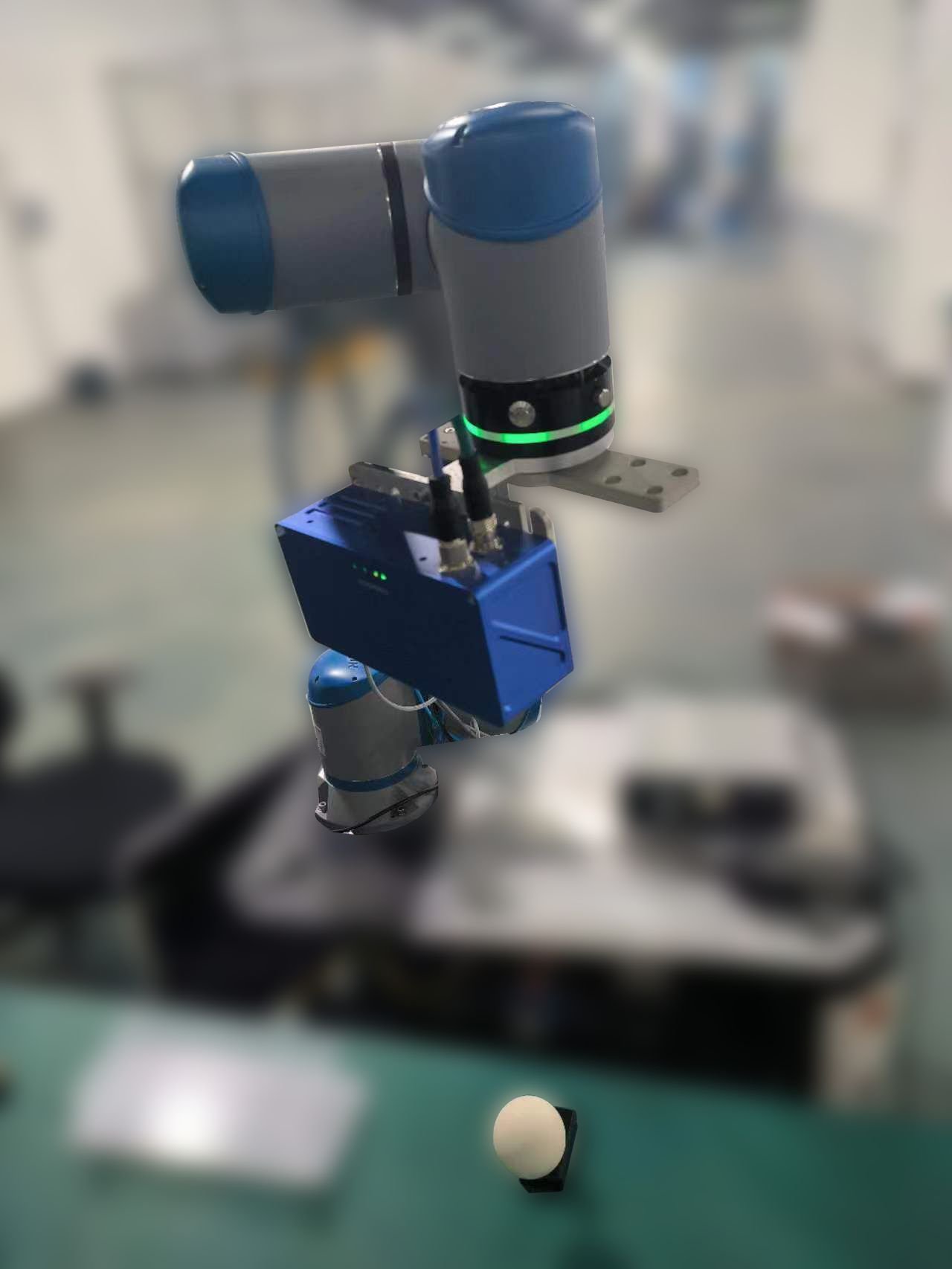
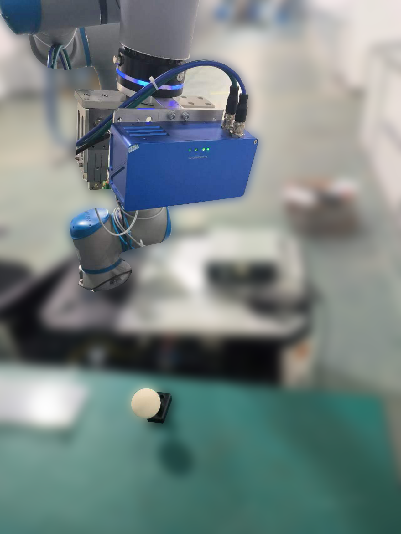
Tip
After moving to a position, click the Capture & Detect button to enter the calibration recognition interface. Click the sphere’s center with the mouse, then click Recognize. Once recognized successfully, click Confirm to add a data entry. Repeat this process about 15 times.
Calibration Calculation#
Once 15 sets of data have been added, click the Calibration button, as shown below.
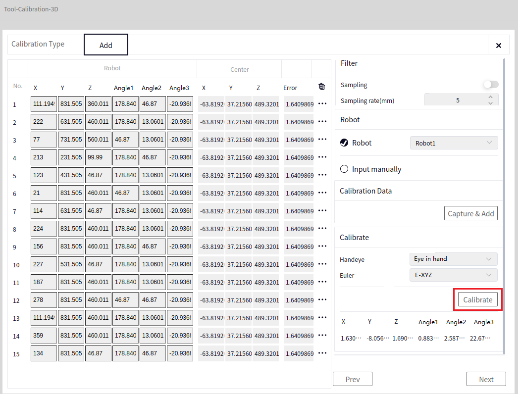
Save#
After successful calibration, you can proceed to the data saving interface by clicking Next, as shown below.
After Calibration, click Next to reach the Save data interface. Click the arrow indicated below to choose the file name and path to save the file, then click Save Result.
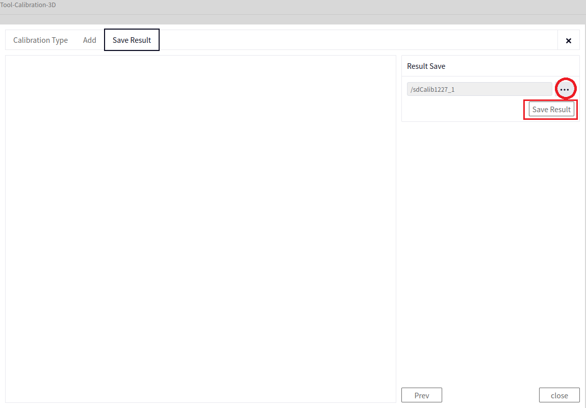
Tip
The saved file will automatically have the suffix .dmcalib. Remember the name slightly, as it will be used in the later 3D Hand-Eye Calibration Conversion operator.
This introduces Manual Calibration. When choosing Automatic Calibration, set the parameters for Generate Pose, and the system will automatically calibrate. When using automatic calibration, reduce the robot’s movement speed appropriately.
Method Two (3D Calibration Board)#
For more details, refer to: Software Operation Guide->Tools->3D Hand-Eye Calibration->Calibration Board (Based on Point Cloud and Image)
Preparation#
Tip
Before performing 3D calibration with the board, you need to connect a 3D camera (in this case, a Zhiwei camera) and a robot.
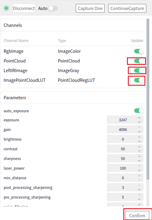
- After connecting the Zhiwei camera, open the camera interface and enable the following camera data:
Point Cloud Image
Left Infrared Image
Image Point Cloud Lookup Table
Other data channels can be disabled, as shown below. After enabling or disabling the channel data, click the Confirm button to apply the changes (also click Confirm after setting camera parameters).
Caution
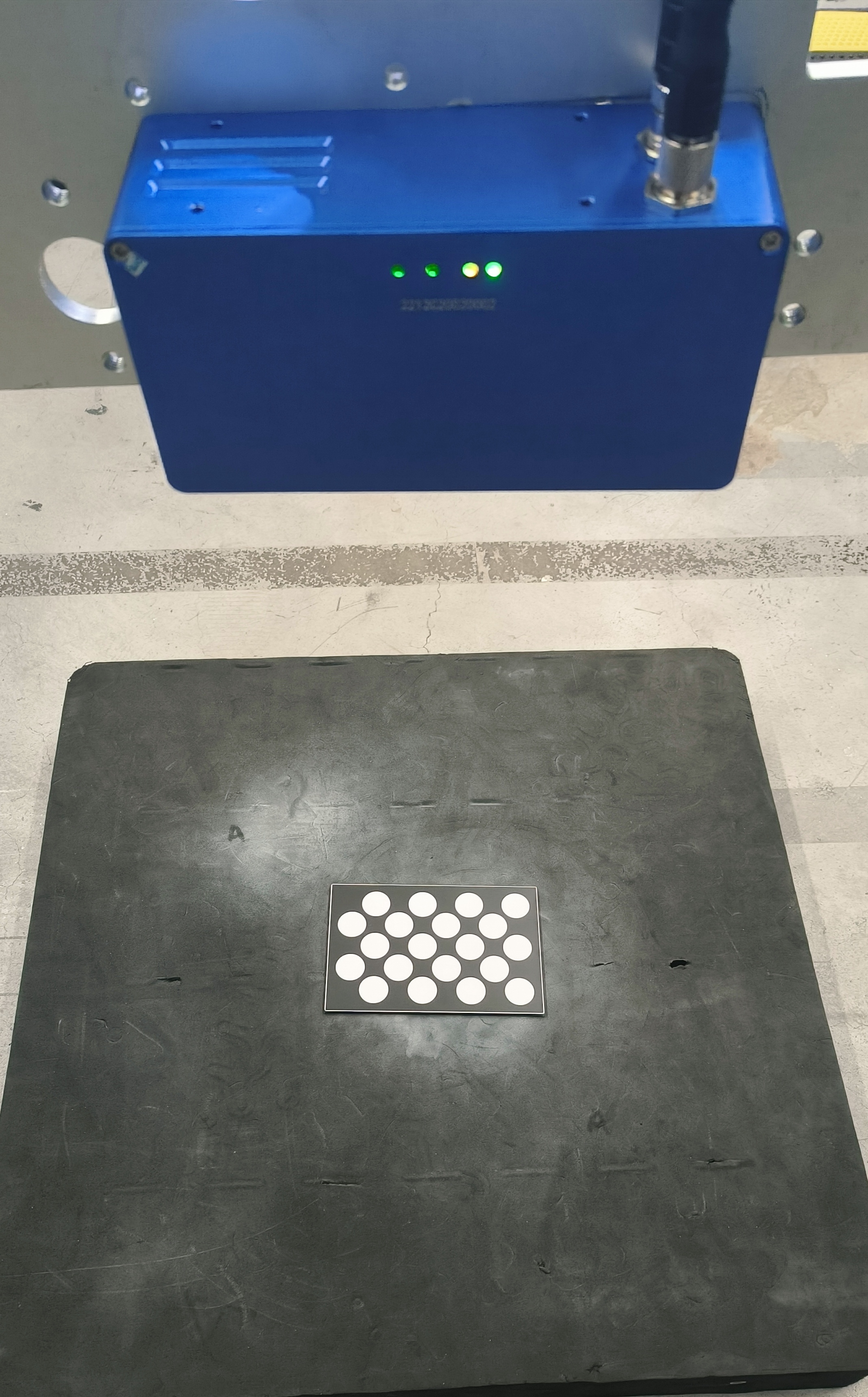
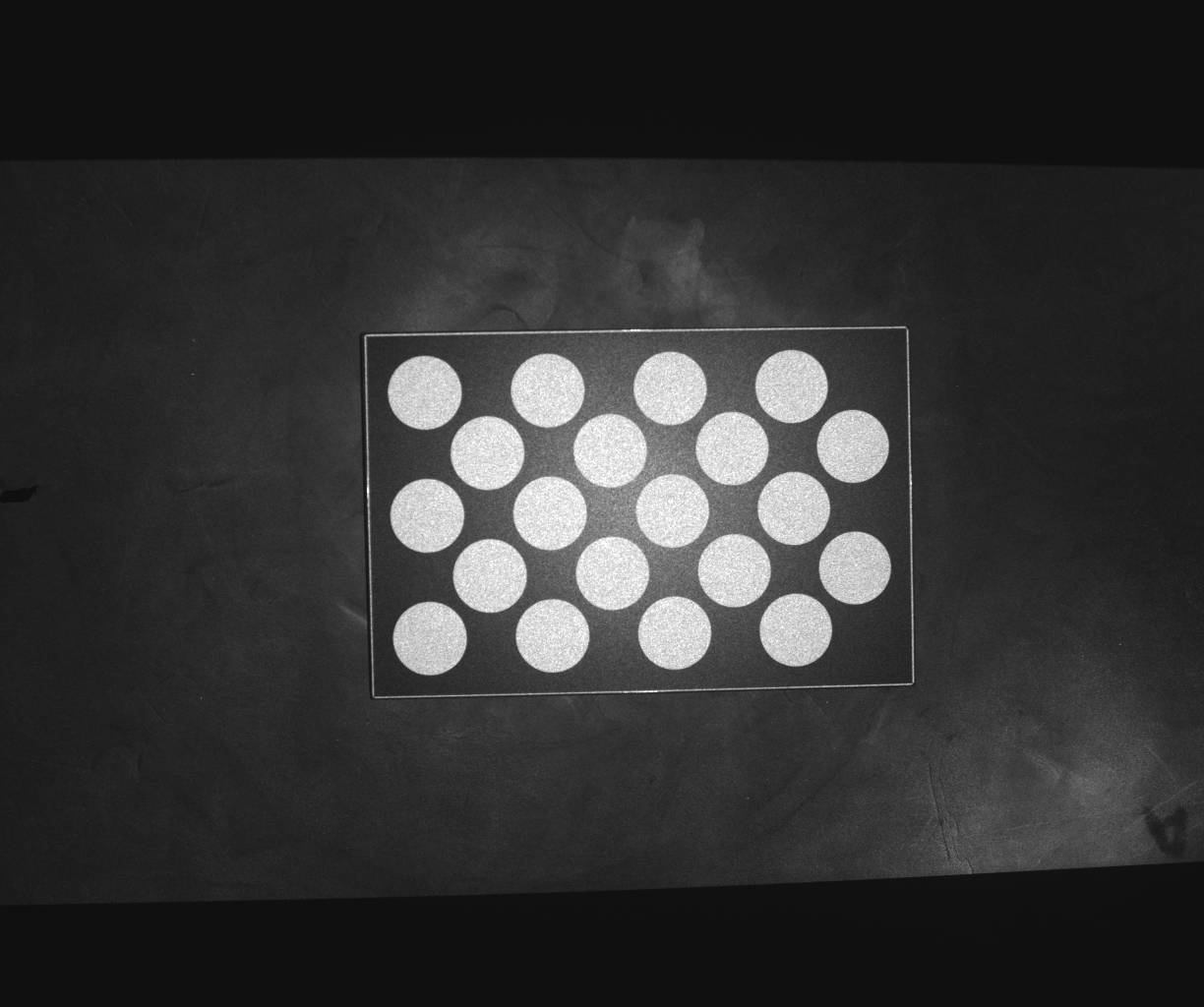
After connecting the camera and robot, the calibration board should be placed flat, and the robot arm should be moved so that the camera lens is parallel to the board. You can move the camera lens while taking photos, checking the Left Infrared Image from the camera. When the calibration board is clearly visible and centered in the image, it is in the correct position.
The initial position of the camera relative to the calibration board is roughly as shown below:
The initial image captured by the camera of the calibration board’s Left Infrared Image is roughly as shown below.
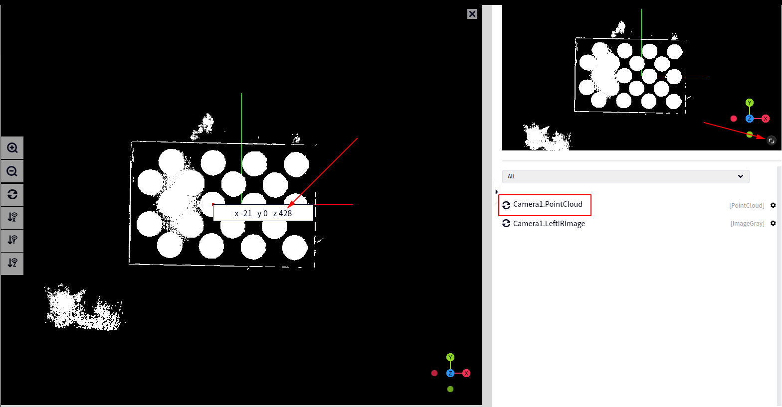
In addition to the image being clear, the initial camera height (distance between the camera and the calibration board) should be maintained at 350-450. You can check the height using the Z coordinate in the point cloud image (click on the point cloud image with the mouse). In the image below, the height is 428.
Entry Point#
As shown below, select Calibration->Calibration-3D.
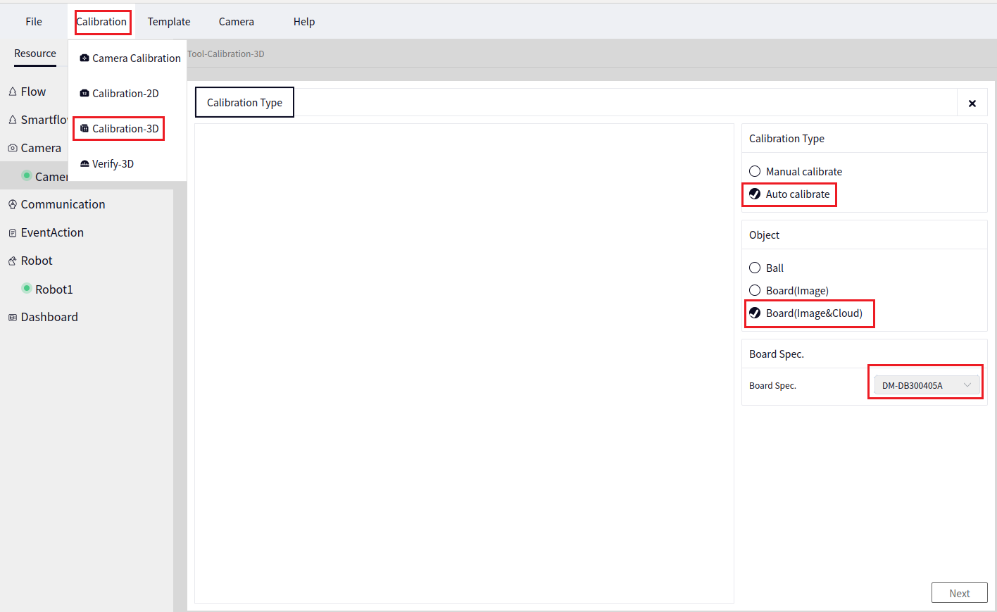
As shown above, there are two calibration methods for the 3D calibration board (manual and automatic). Here we choose Automatic Calibration, with the calibration object as Calibration Board (Based on Image and Point Cloud), and the board size as DB30405A. Click Next to proceed to the following interface.
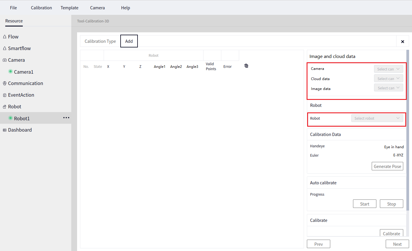
Parameter Settings#
- In the image above, for the image and point cloud data:
- Camera
Select the Zhiwei camera just connected, such as Camera1.
- Point Cloud Data
Select the point cloud image from the connected camera, such as Point Cloud Image.
- Image Data
Select the grayscale image from the connected camera, such as Left Infrared Image.
- In the image above, for the robot data:
Select the connected robot, such as Robot1.
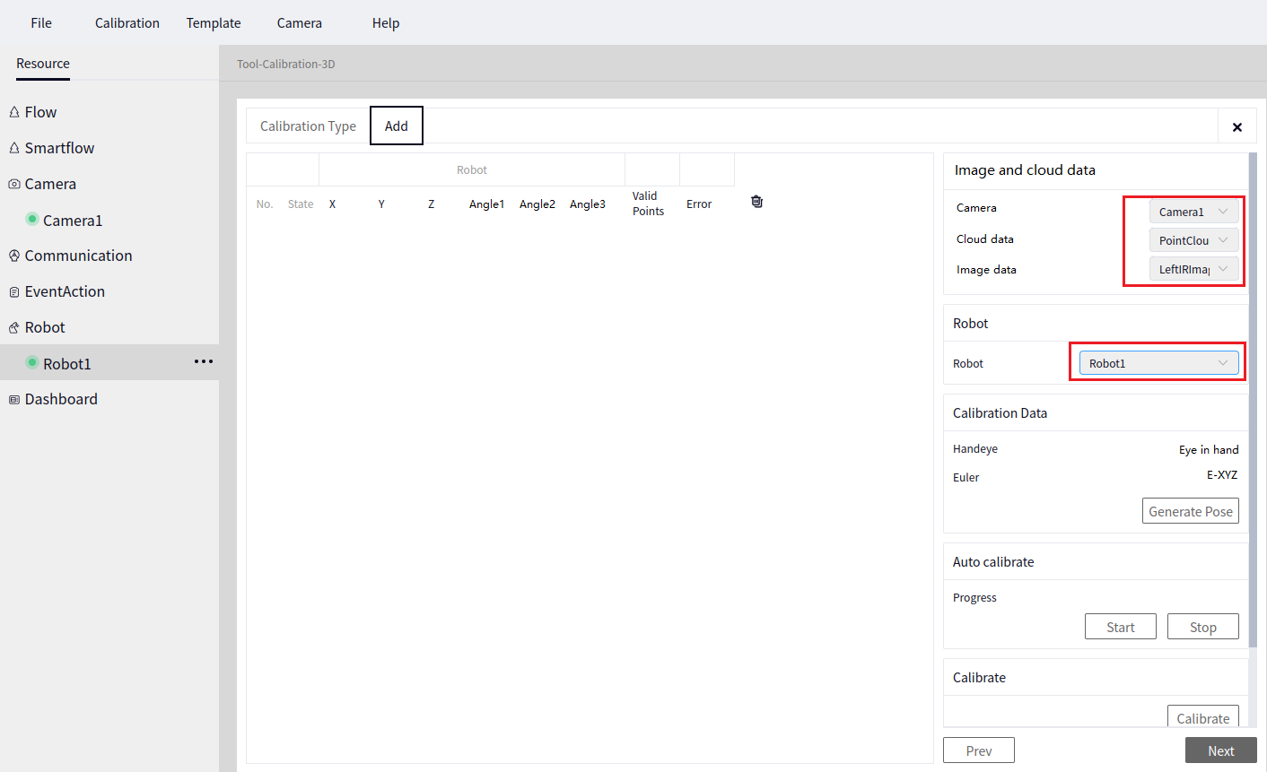
The image below shows the camera and robot data after setting.
Generate Pose#
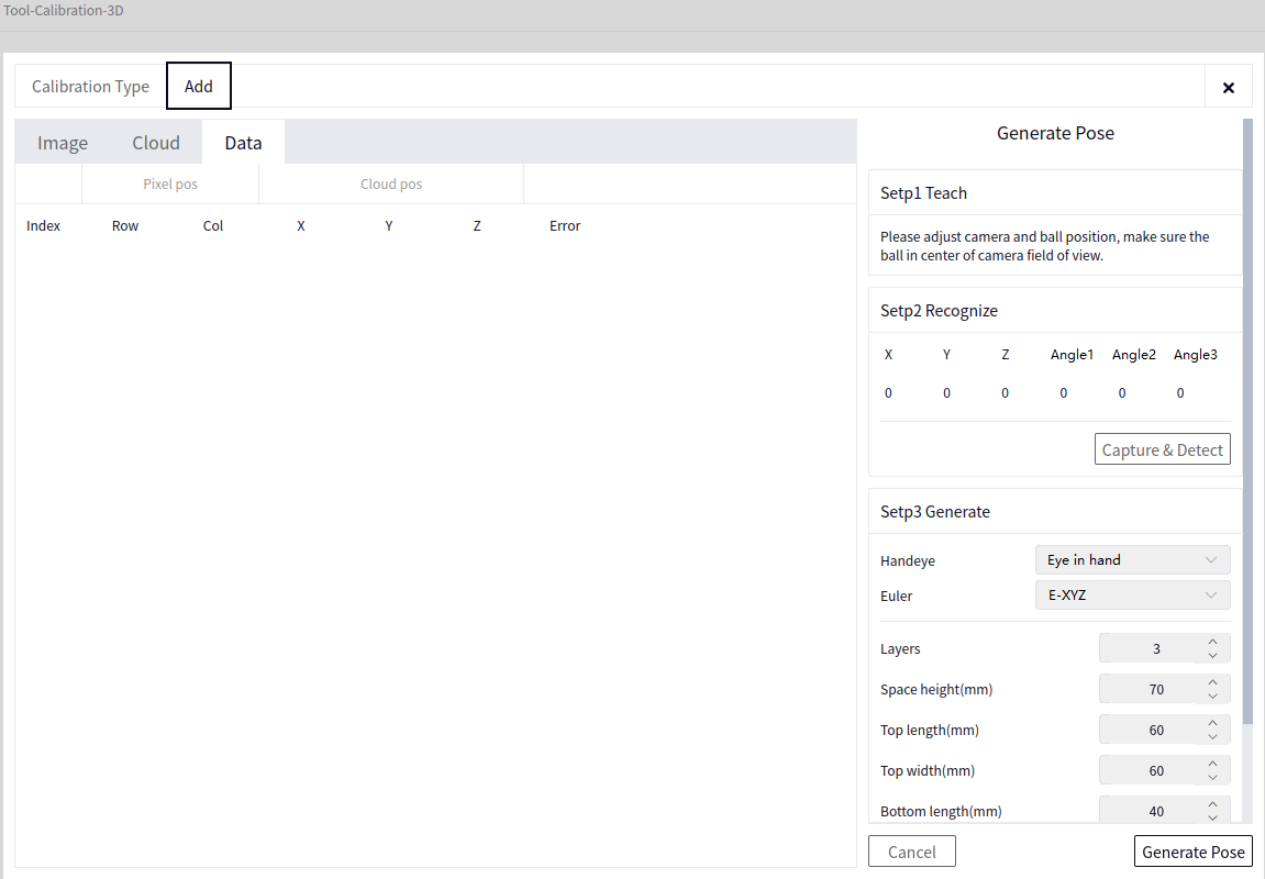
After setting the camera and robot data, click the Generate Pose button. This function generates multiple robot poses. The interface after clicking this button is shown below:
Tip
Before generating poses, ensure that the camera and calibration board are in the optimal position.
As shown above, the Generate Pose interface contains a Capture & Detect button. This button functions as a test to detect whether the current position can recognize the result. Click it once, and if recognition is successful, the recognized data will be displayed in the left data column, as shown below.
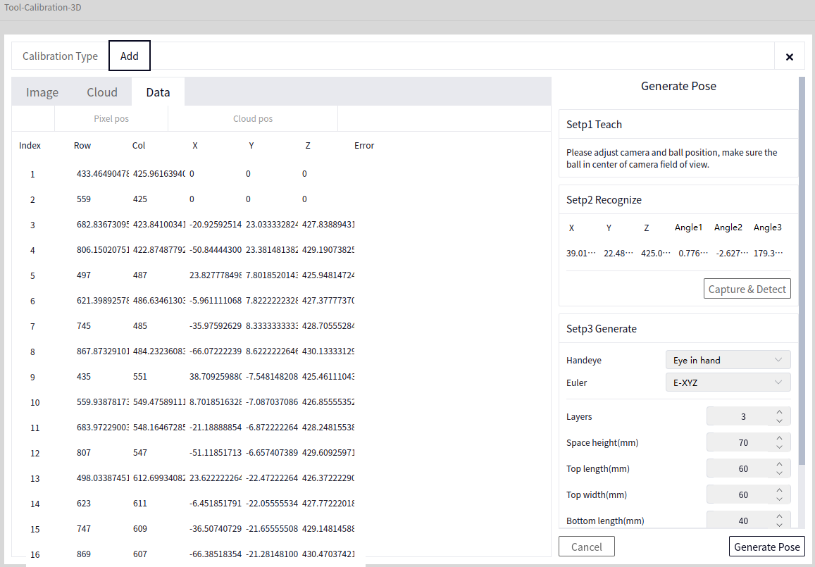
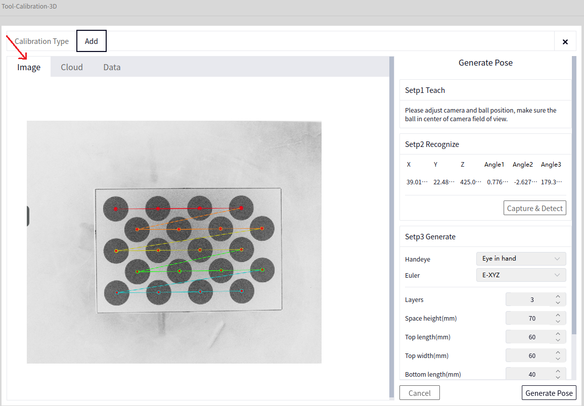
You can view the 2D and 3D data by clicking the 3D Point Cloud and 2D Image buttons, respectively. The images below show the 3D and 2D recognition results:
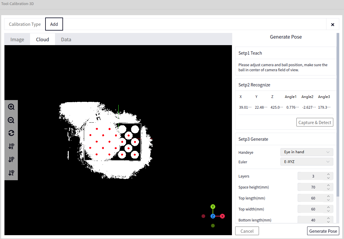
The image above shows the 3D data, and the image below shows the 2D image recognition result:
Tip
If there is no response or an error pop-up when clicking the Capture & Detect button, check the camera and calibration board positions and whether the image is too bright or too dark (adjust camera parameters as needed).
Once recognition succeeds with the Capture & Detect button, you can set the parameters for generating poses, as shown below.
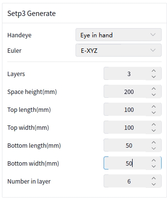
In the image above, Hand-Eye Type and Euler Angle Type do not need to be set at this time.
Pose Layers: The number of spatial heights the camera will move to, default is 3, meaning the camera will move to 3 different heights
Spatial Height: The height of the space.
Top Layer Length: The length of the top layer.
Top Layer Width: The width of the top layer.
Bottom Layer Length: The length of the bottom layer.
Bottom Layer Width: The width of the bottom layer.
Rotation Count: The number of poses in each layer.
Tip
The spatial height, top layer length, and top layer width should not be set too large, as the robot arm has a fixed length, and some poses may not be reachable. Typically, the spatial height is set to around 100-120, and the top layer length and width can be left at the default of 100.
After setting the parameters for generating poses, click Generate Pose, and the effect will be as shown below.
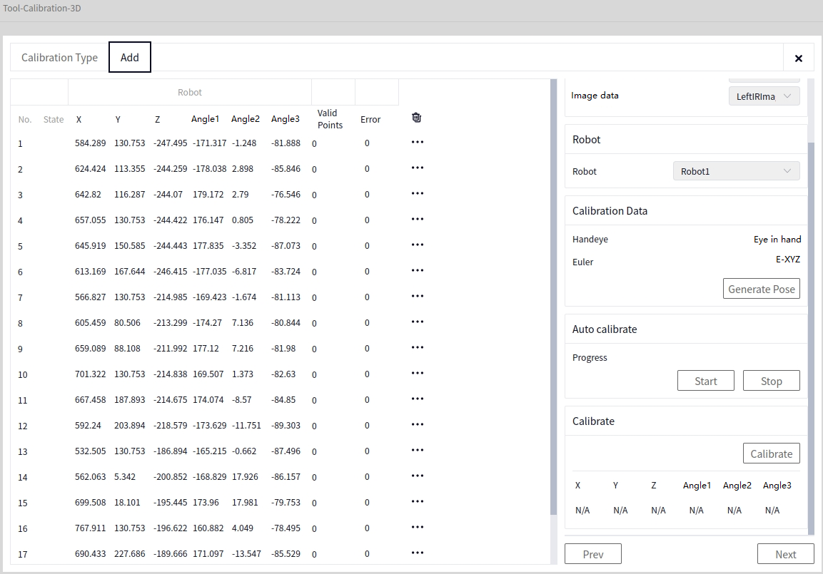
Automatic Calibration#
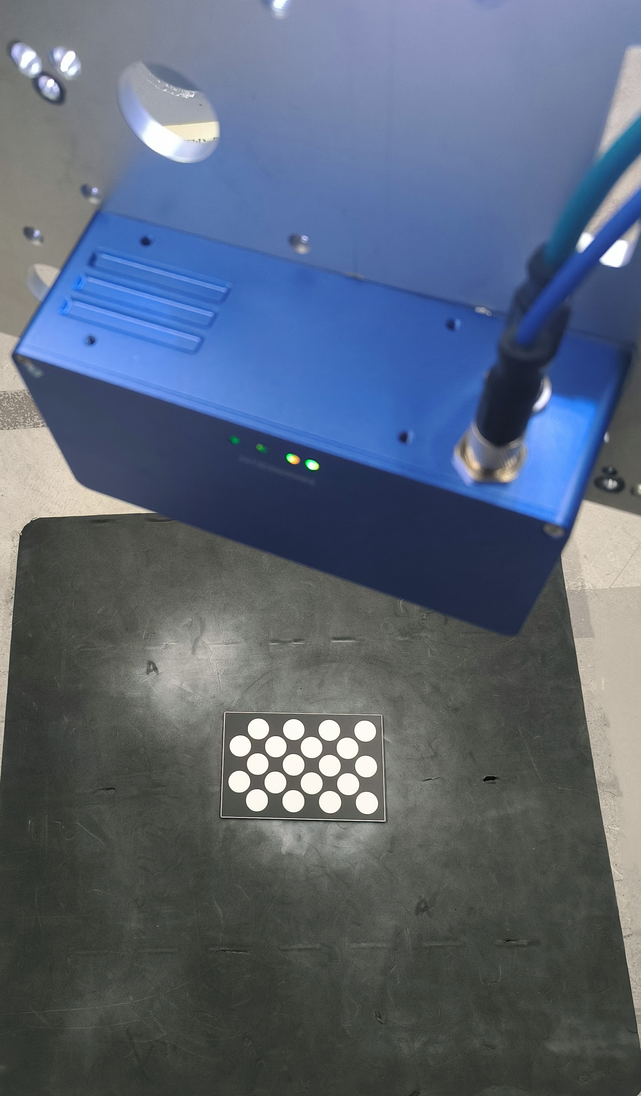
The camera will perform calibration at different heights in the following positions, as shown below:
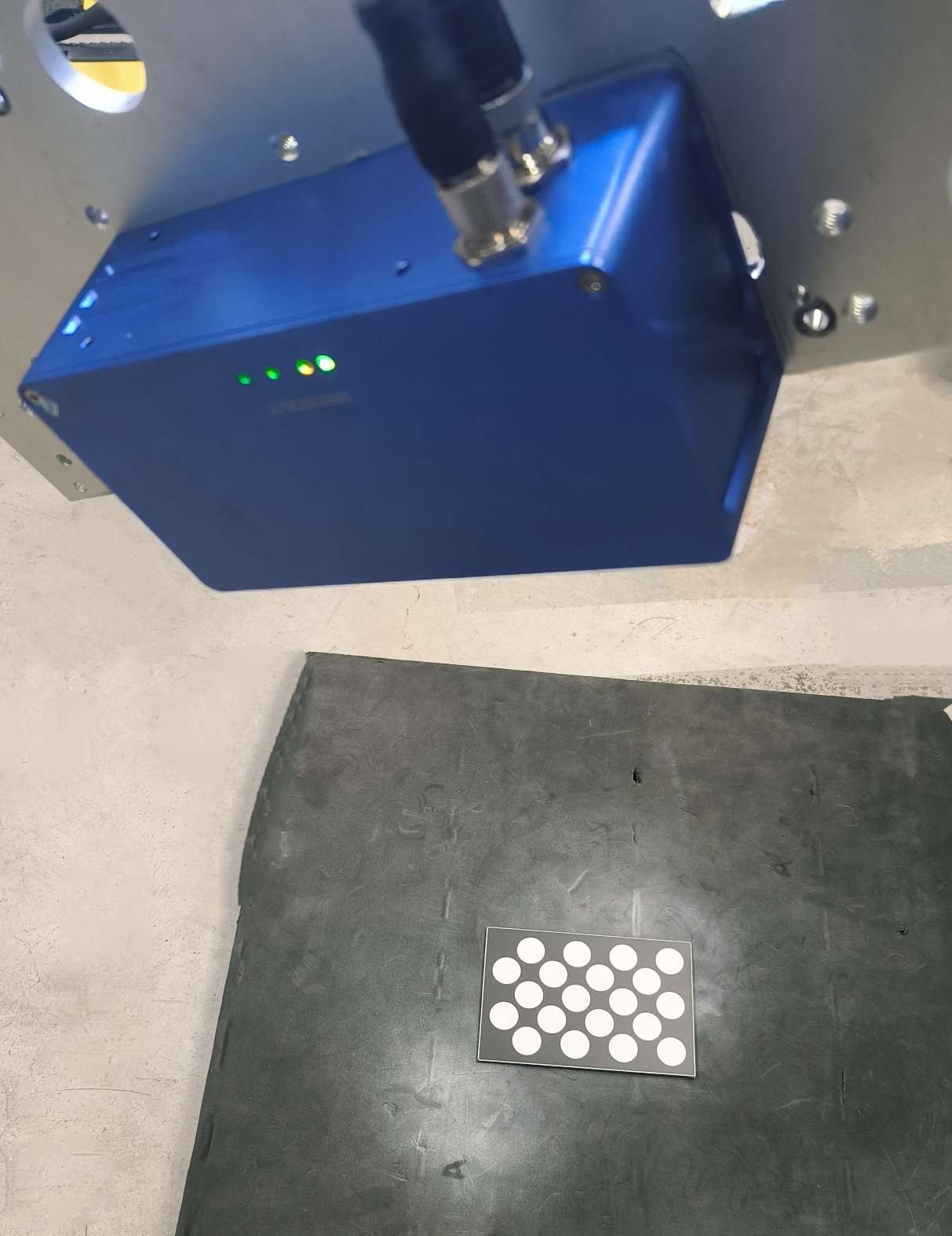
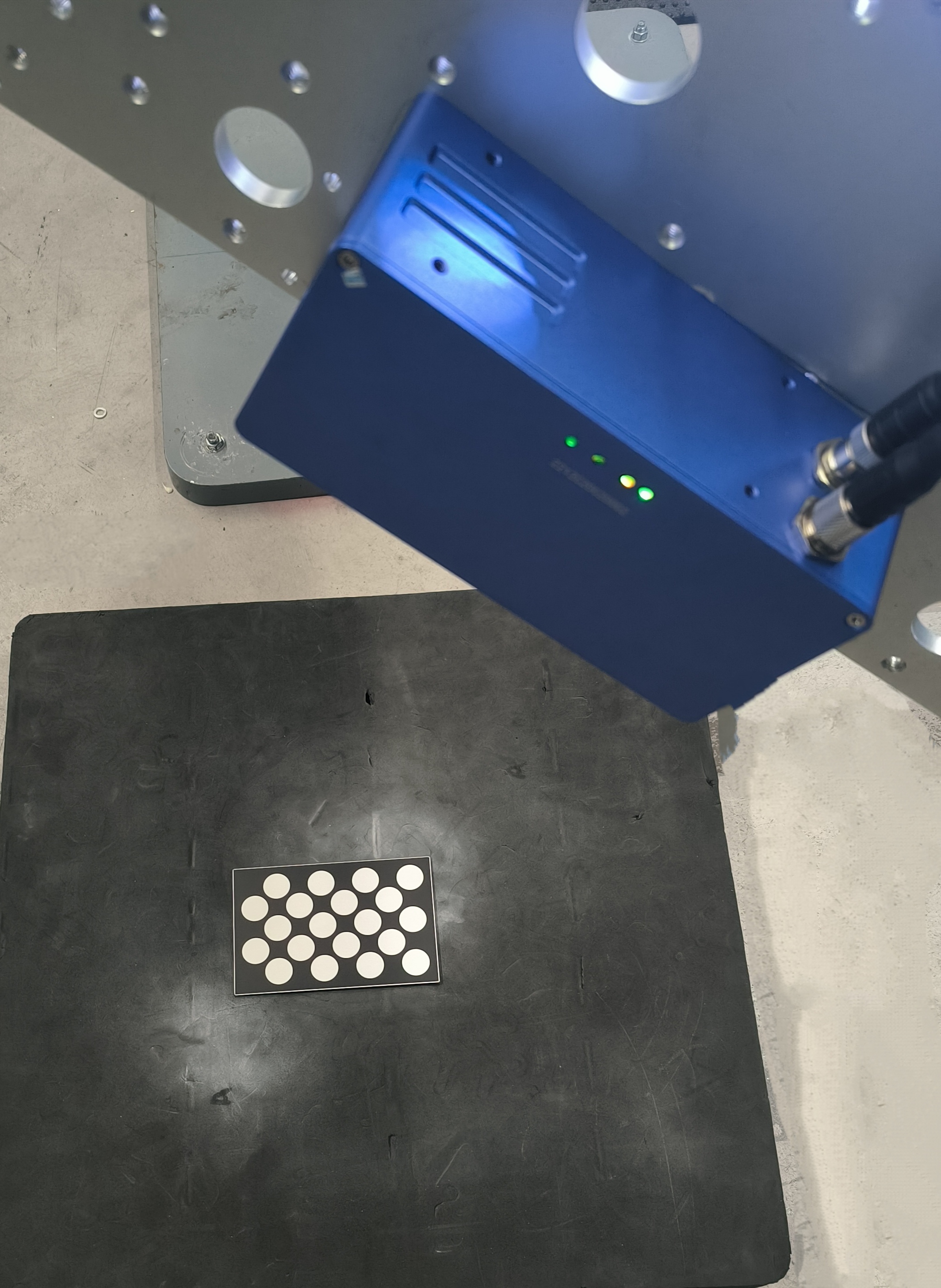
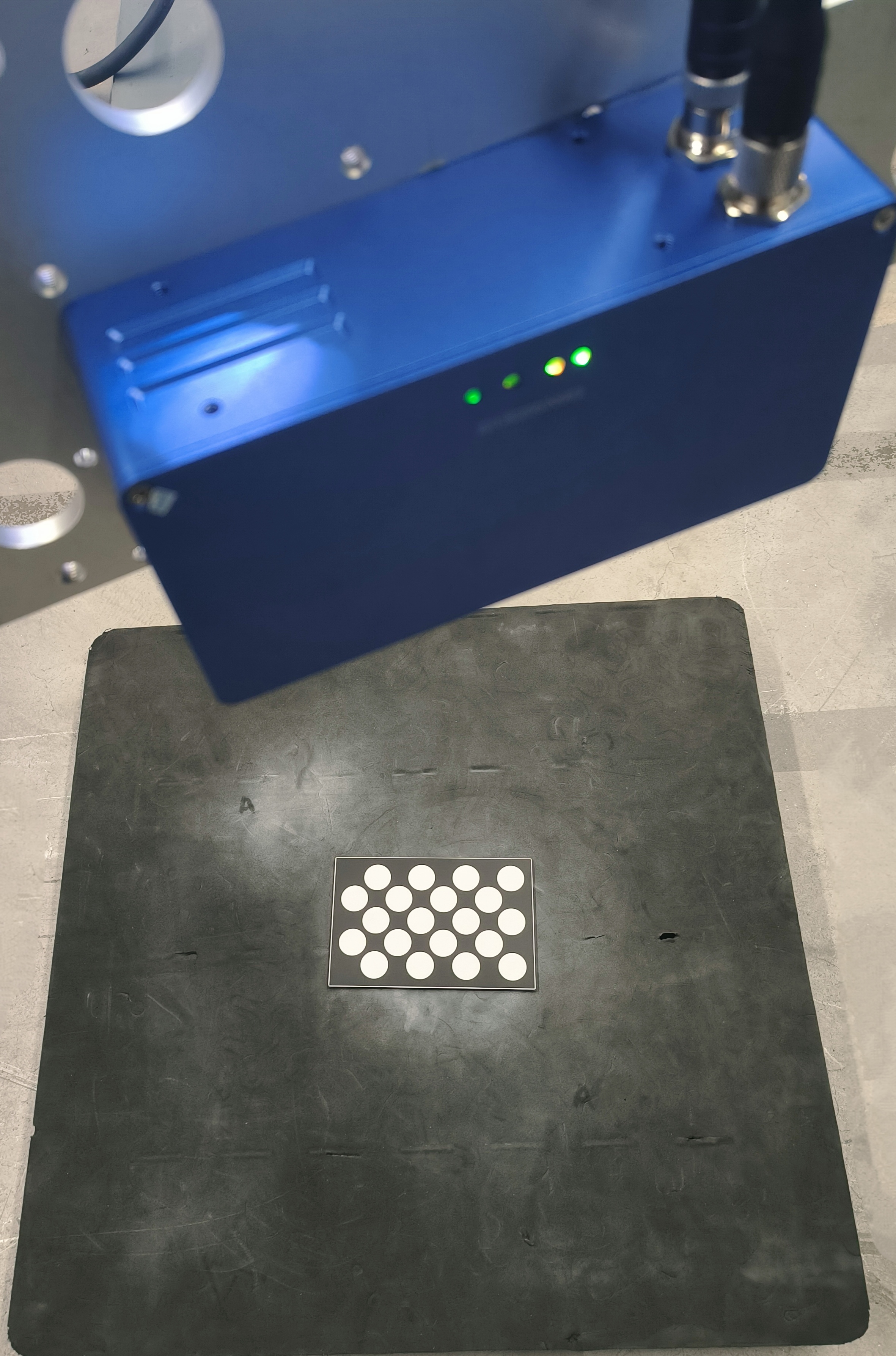
Tip
Automatic calibration does not require manually moving the robot. For manual calibration, the camera must be moved to directly above, upper-left, upper-right, front, and rear of the calibration board, and at three different heights in these directions, for a total of 15 positions. Ensure that after moving, the camera can capture the calibration board.
At this point, click Start, and the software will begin automatic calibration according to the generated robot poses, line by line. The image below shows the result after successfully calibrating 5 lines.
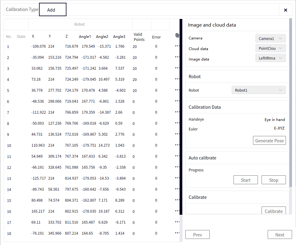
If the calibration process needs to be stopped, click the Stop button.
After waiting for a while, all calibration data will be completed, as shown below.

View Data#
After the calibration is complete, you can click the button at the end of a row of data to view the data for that pose. The image below shows the button to view the data for the second row.
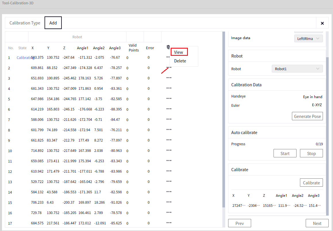
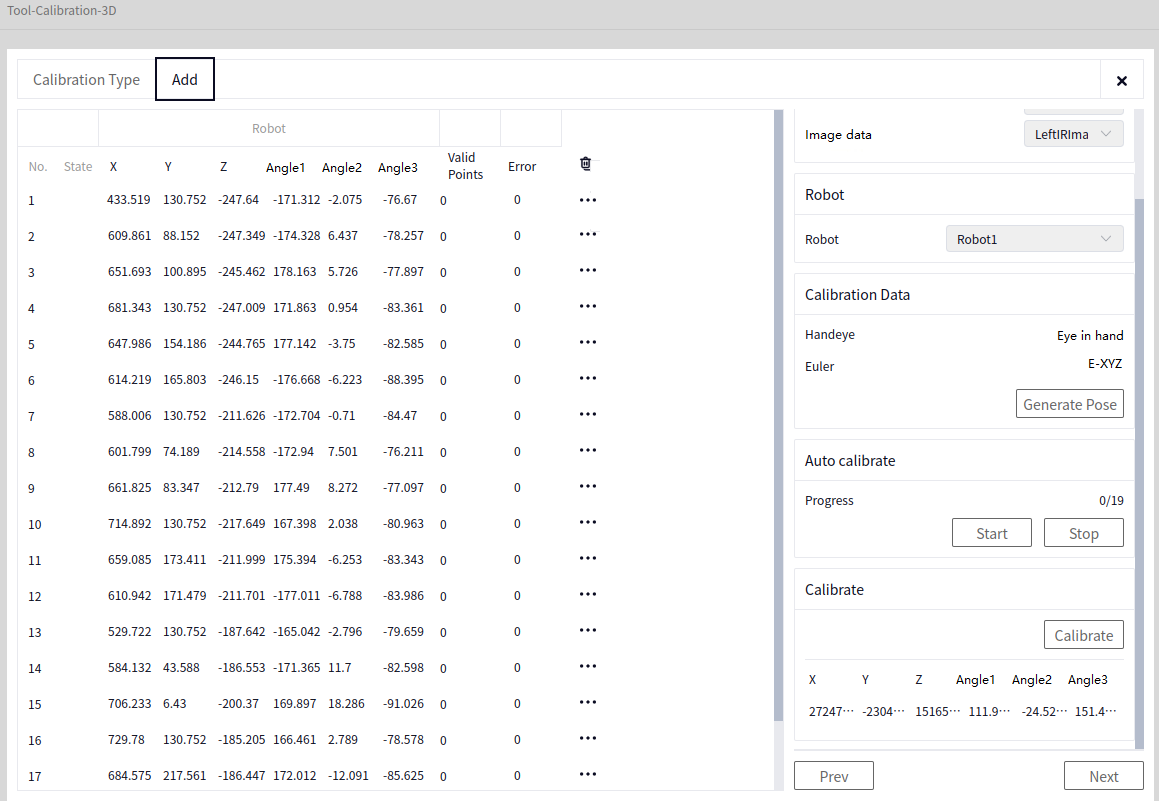
When viewing data, you can switch between Data, 2D Image, and 3D Point Cloud to view different types of data. The following three images show these views:
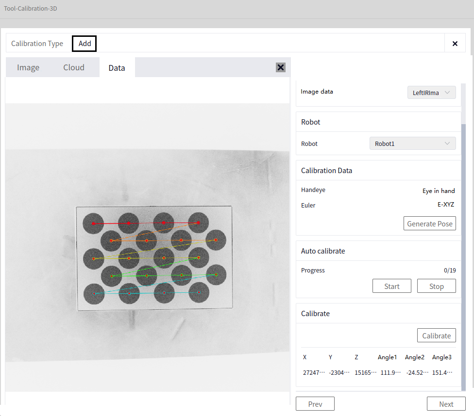
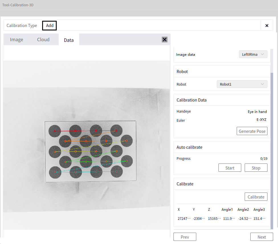
Calibration Calculation#
Click the Calibration button, and at this point, the Error for each row of data will appear. Failed or poorly recognized data will be automatically deleted.
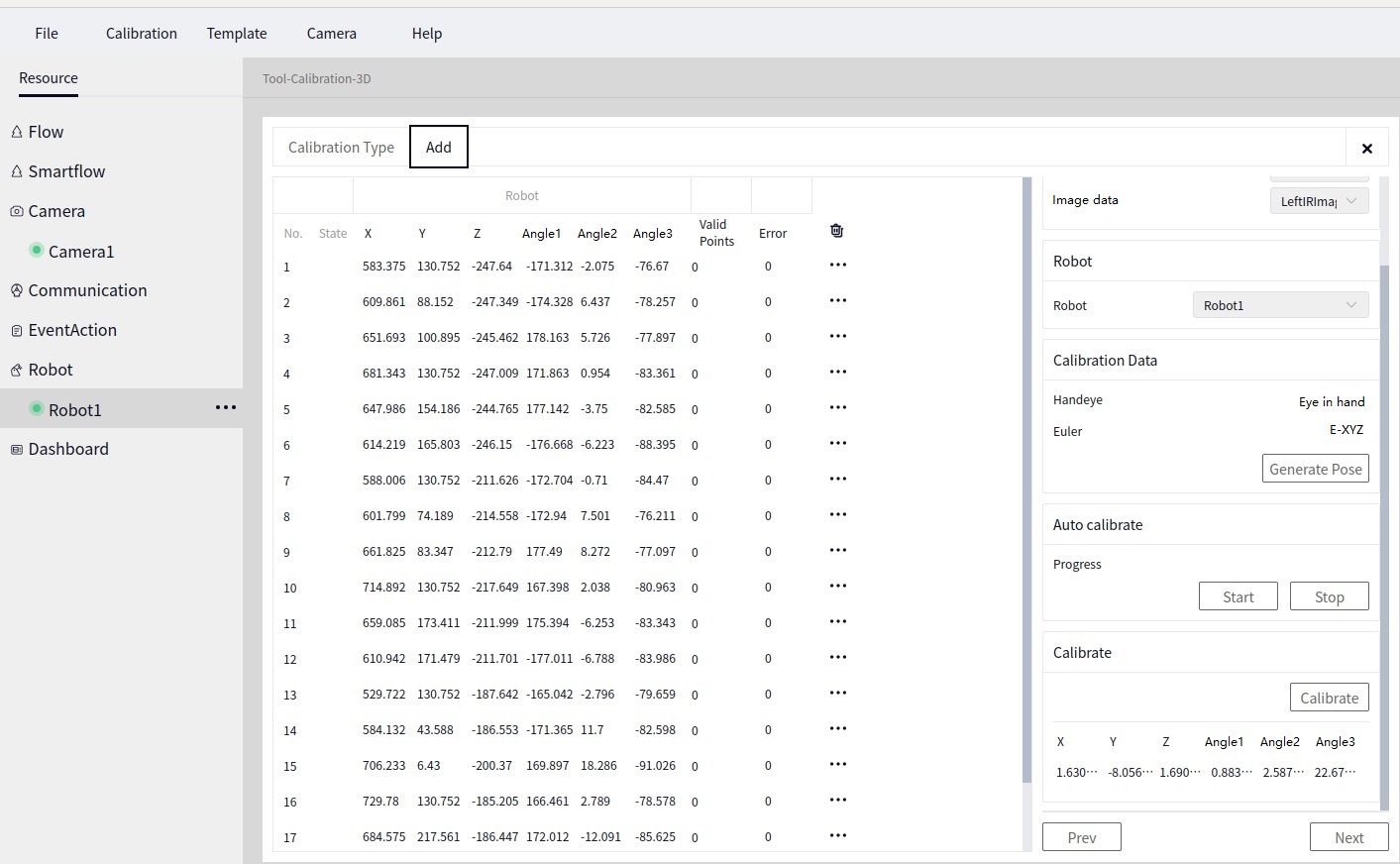
The image above shows the result after clicking Calibration. Each row’s error is less than 1, meaning the result can be used. If any row has a large error, it can be deleted, and then the calibration calculation can be re-run.
Save#
After successful calibration calculation, you can proceed to the data saving interface by clicking Next, as shown below.
After Calibration Calculation, click Next to reach the Save data interface. Click the arrow indicated below to choose the file name and path to save the file, then click Save Result.
Tip
The saved file will automatically have the suffix .dmcalib. Remember the name slightly, as it will be used in the later 3D Hand-Eye Calibration Conversion operator.
3D Template Creation#
For more details, refer to: Software Operation Guide->Tools->3D Template Creation
First, place the mark block next to the calibration sphere, with the actual position roughly as shown below.
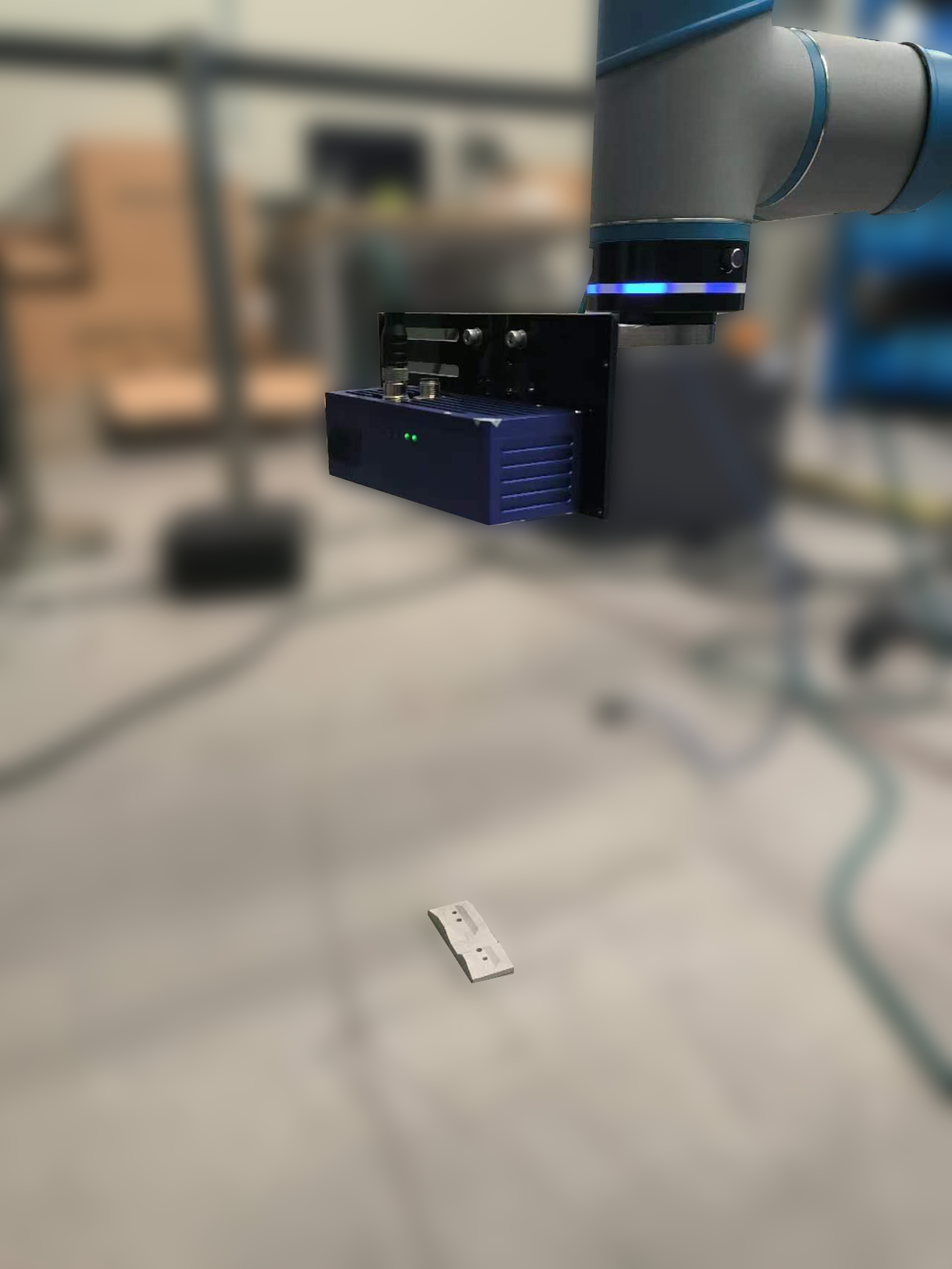
Two methods are provided below, with Method Two being recommended.
Method One#
Entry Point#
Click Template, then Template3-3D to enter the 3D Template Creation tool interface, as shown below.
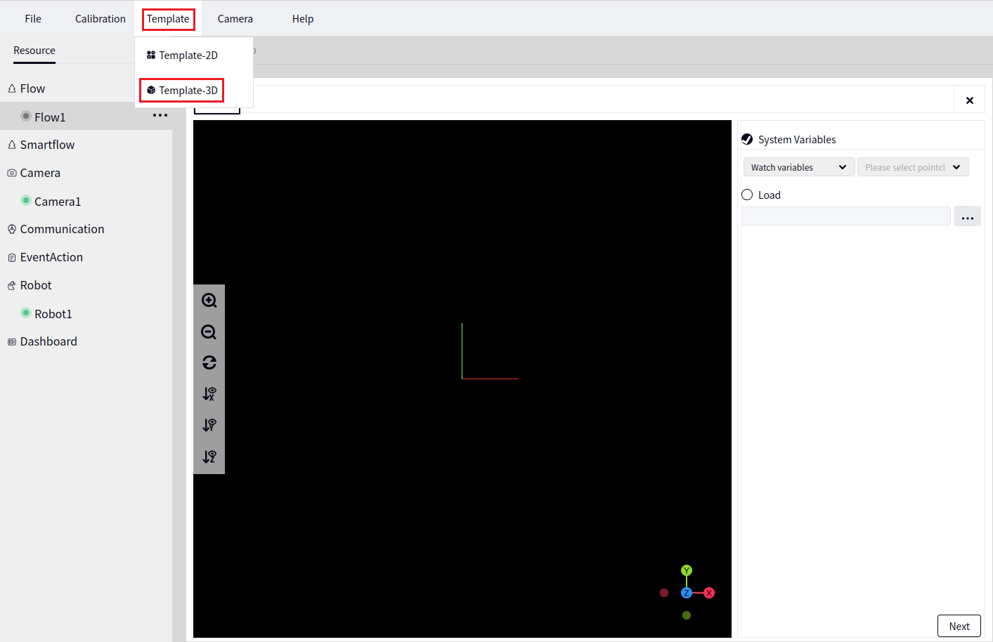
In the image above, select System Variables, then choose the pointcloud (point cloud data) of the connected camera from the Global Variables, for example, Camera1.pointcloud.
Point Cloud Trimming#
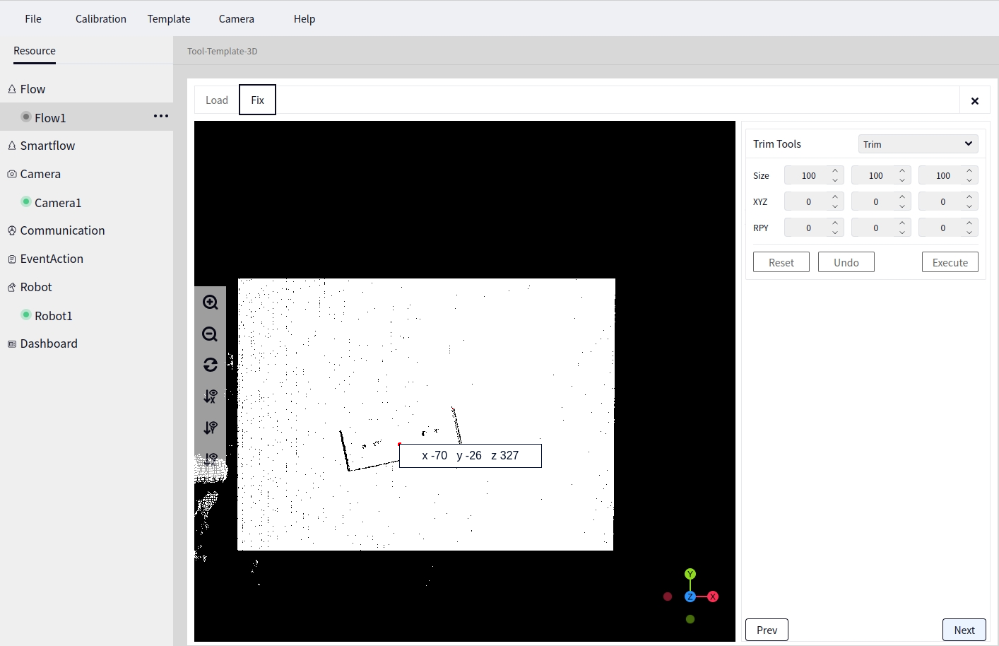
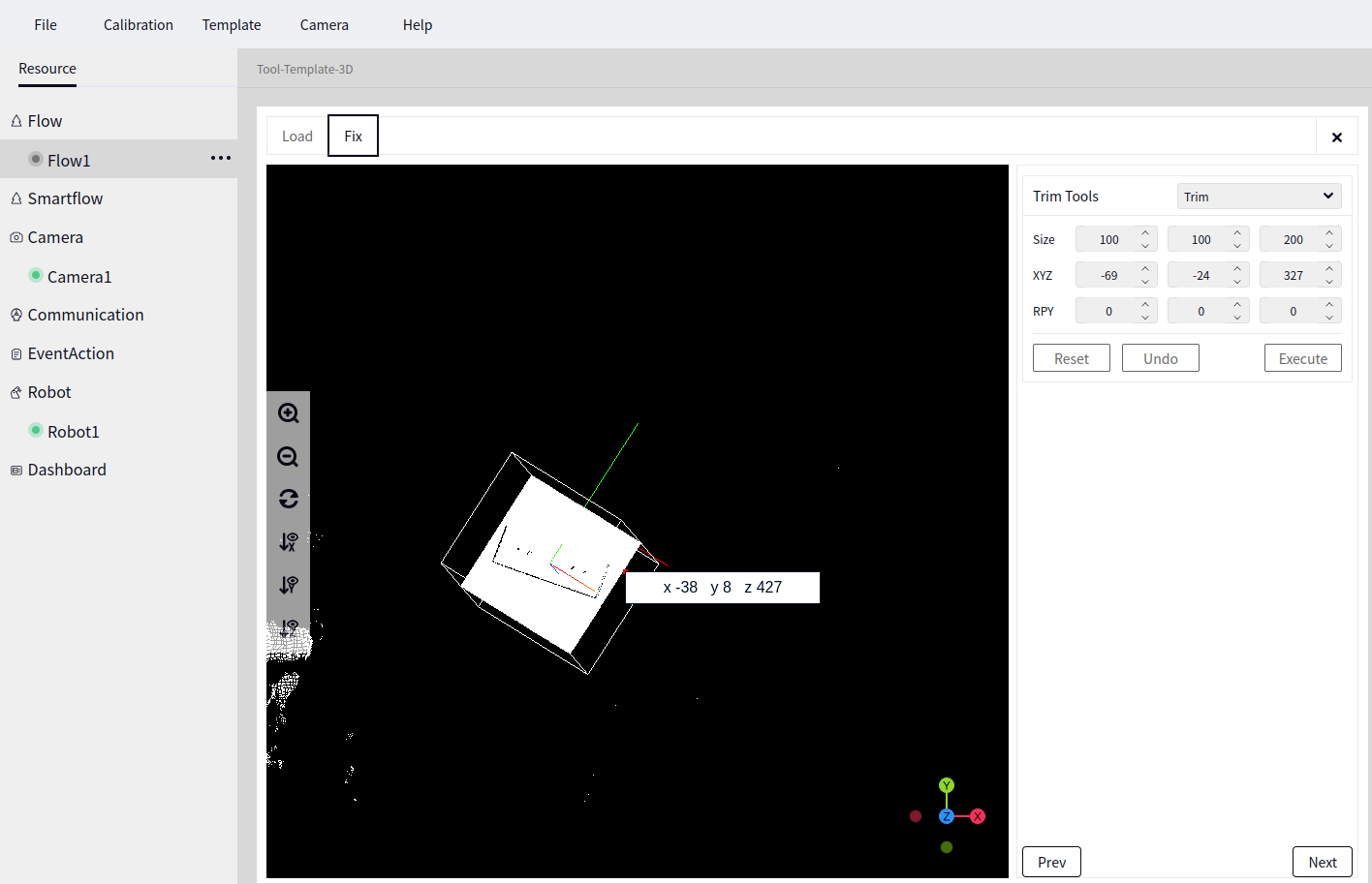
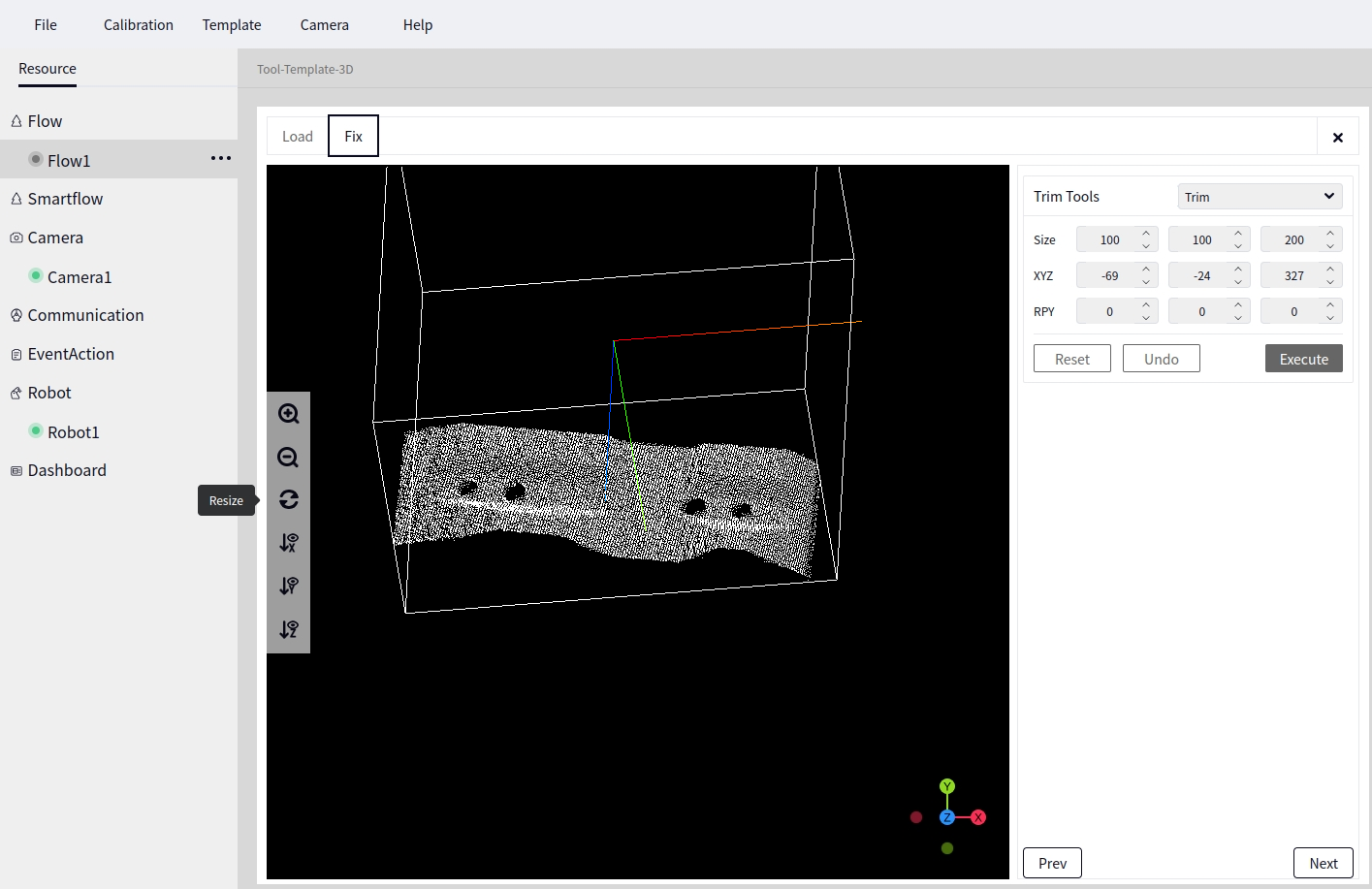
At this point, click Next to enter the Point Cloud Trimming interface. The default tool is cropping. Zoom in on the point cloud, and click the center of the template with the mouse. The xyz coordinates will be displayed. Enter these xyz values in the xyz fields below the cropping tool. For Size, first input 100,100,100, then click Execute and View. If the result is unsatisfactory, click the Undo button.
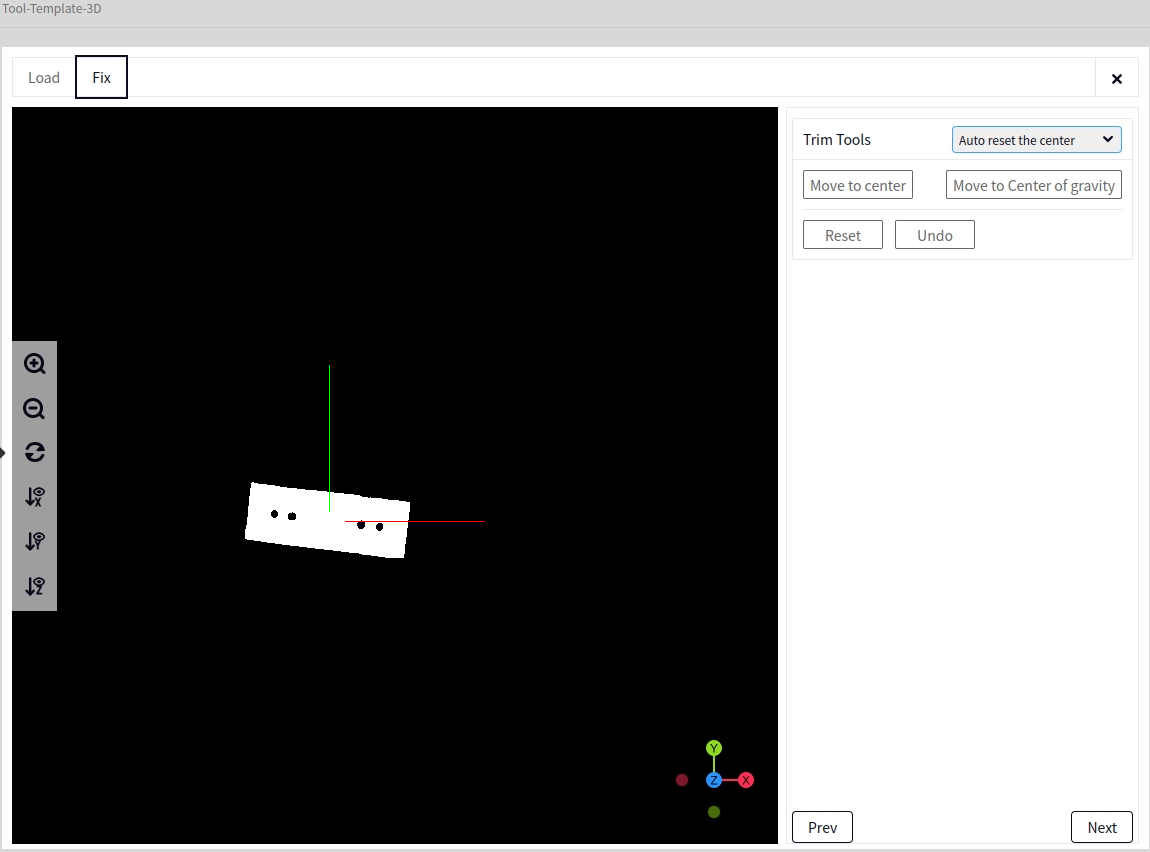
Auto Reset Center#
In the trimming tool, select Auto Reset Center, then click Move to Center, as shown below.
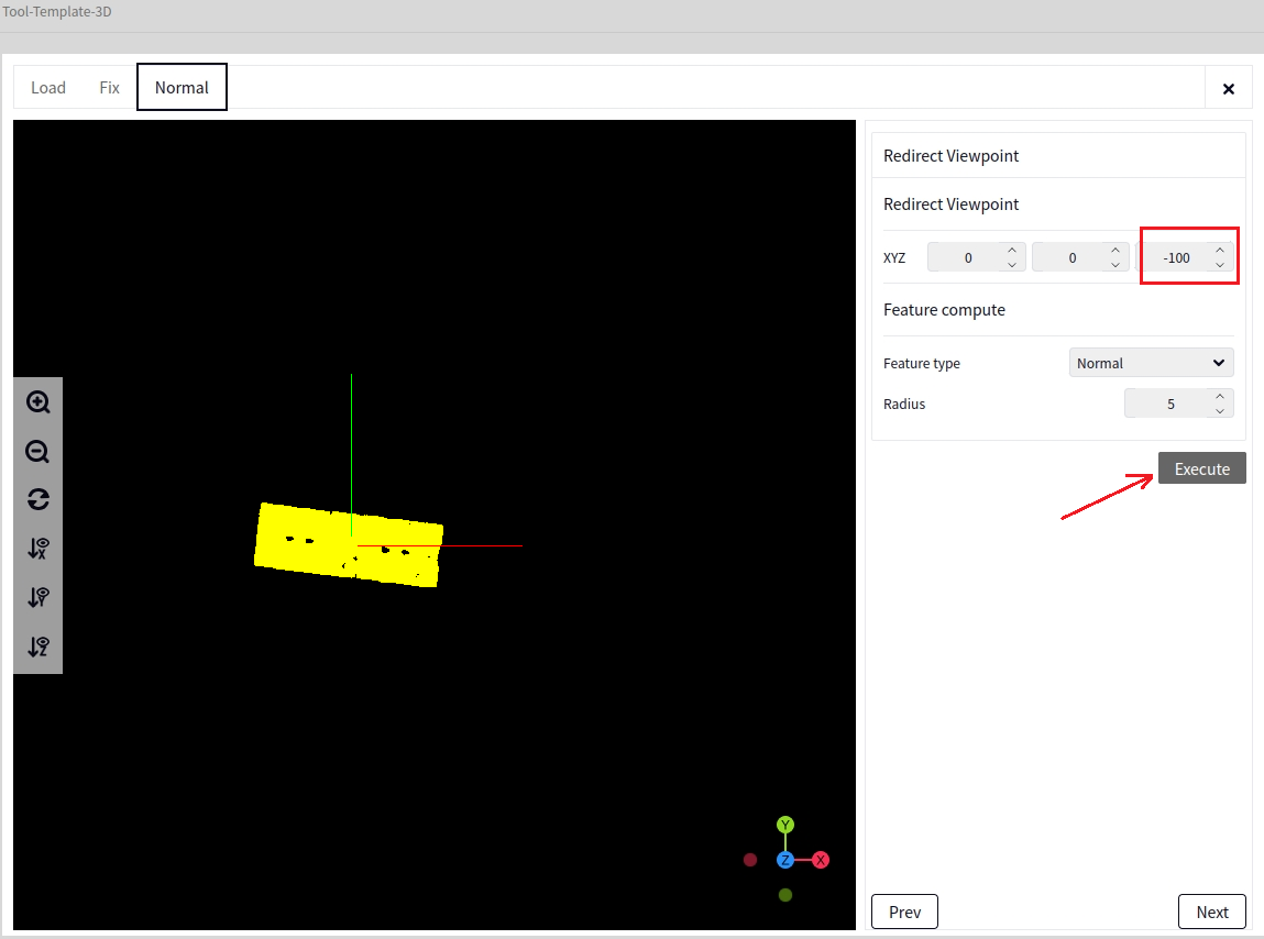
Normal Calculation#
After the above step, click Next to reach the normal modification interface. Set z=-100, then click Execute. The image below shows the result after calculating the normals.
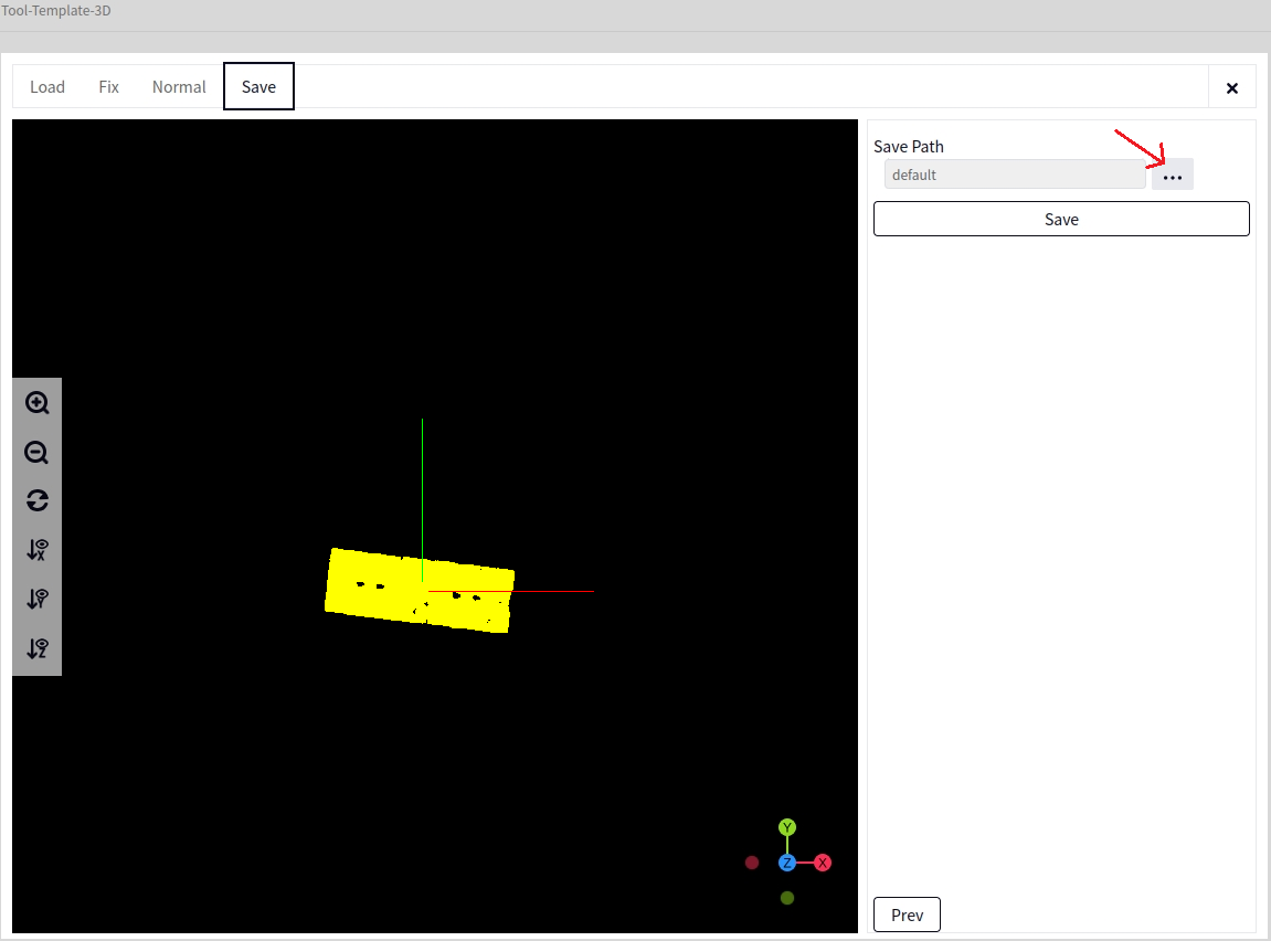
Save#
After the above step, click Next to reach the save template interface. Click the arrow indicated below to select the folder and name to save the file. Finally, click Save Template.
Method Two:#
Place the mark block directly under the camera, click Camera Capture once, and view the point cloud data output by the camera in the Global Variables. Zoom in on the point cloud, and if you can find the mark block’s point cloud, proceed.
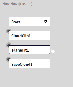
Create a new Process, and add the 3D Vision -> ROI -> CloudClip operator, then add the 3D Vision -> Detection -> Plane Fitting operator and the 3D Vision -> Input/Output -> SaveCloud operator, as shown below.
Double-click the CloudClip operator, set the input to the camera’s point cloud data, find the mark block’s point cloud in the camera’s output, and click the center of the mark block. The interface will display xyz coordinates. Record this coordinate, and enter it in the X Translation, Y Translation, and Z Translation fields of the CloudClip operator. Set the bounding box dimensions to 100 in each direction.
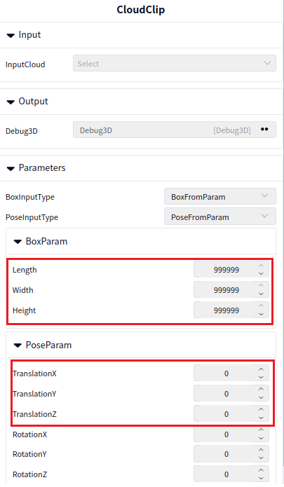
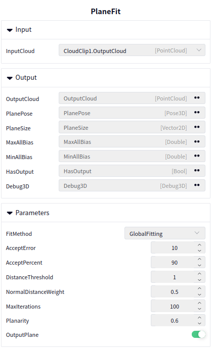
Double-click the PlaneFit operator, set the input to the output of the CloudClip operator, and configure the parameters as shown below.
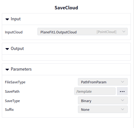
Double-click the SaveCloud operator, set the input to the output of the Plane Fitting operator, and choose a file name for saving. The image below shows the configuration.
By following the steps in Software Operation Guide -> Tools -> 3D Template Creation, you can enter the template creation interface for the mark block. In the Load Point Cloud interface, select the SaveCloudd locally via the SaveCloud operator, then click Next and follow the steps in Method One for Auto Reset Center -> Normal Calculation -> Save to complete the process.
3D Mark Block Positioning Process#
For more details, refer to: Software Operation Guide->Process Management->Process and Template->Add Process from Preset Template, and add a 3D mark block positioning process, as shown below.
Click the first icon after the process to add a 3D mark block positioning process from the preset template, as shown below.
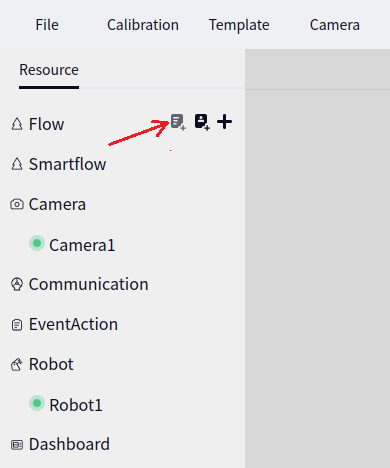
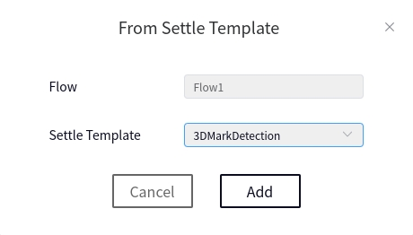
After adding, click the process name, and the following interface will pop up, indicating that the 3D mark block positioning process was successfully added.
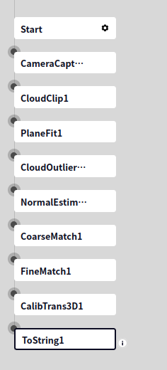
Camera Capture#
The input for the Camera Capture operator should be set to the connected camera, for example, Camera1.
CloudClip#
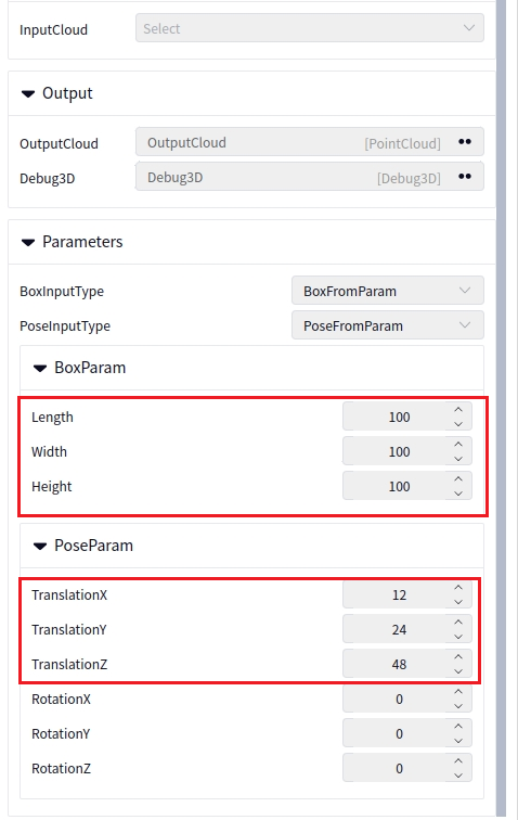
Set the input for the CloudClip operator to the output of the Camera Capture operator. Find the mark block’s point cloud in the camera’s output, click the center of the mark block, and the interface will display xyz coordinates. Record this coordinate, and enter it in the X Translation, Y Translation, and Z Translation fields of the CloudClip operator. Set the bounding box dimensions to 100 in each direction.
For example, if the mark block’s point cloud center is (12,24,48), the parameters should be input as shown below.
Plane Fitting#
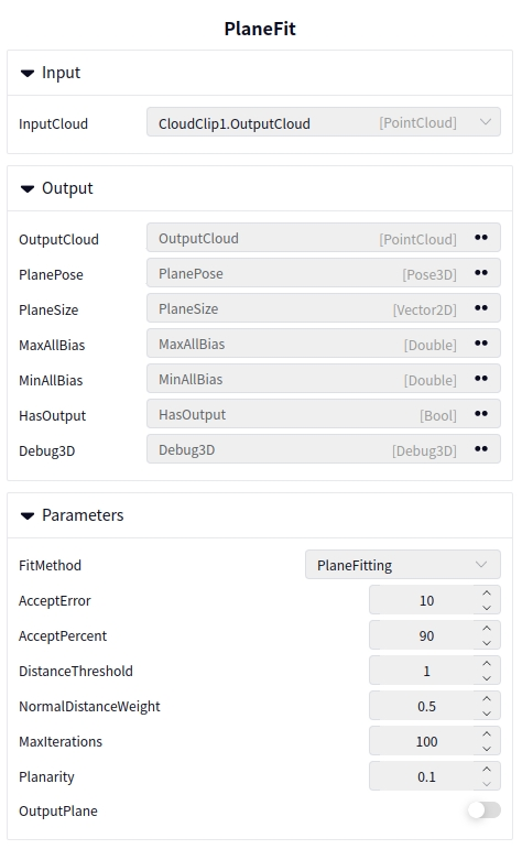
Set the input for the Plane Fitting operator to the output of the CloudClip operator. This operator removes the plane below the mark block’s point cloud. Generally, the parameters can be set as shown below. If the plane is not removed, increase the Distance Threshold by 1 each time.
Statistics Filter#
Set the input for the Statistics Filter operator to the output of the Plane Fitting operator. This operator filters out noise points from the point cloud. Generally, the parameters can be set as shown below.
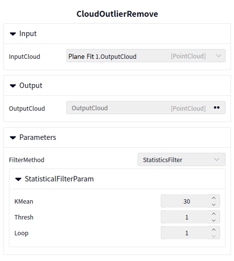
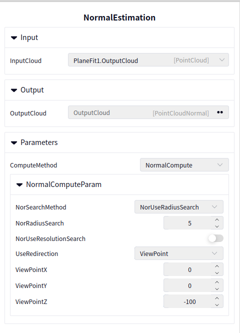
Normal Compute#
Set the input for the Normal Compute operator to the output of the Statistics Filter operator. This operator calculates normals. Set the parameters as shown below.
Coarse Matching#
Set the input for the Coarse Matching operator to the output of the Normal Compute operator.
- Template Path
Meaning: The 3D template file path. Select the template created earlier using the 3D Template Creation tool. The file suffix is dmtemp.
- Angle Subdivision Count
Meaning: An internal parameter for setting the angular quantization count. No need to adjust, set to 60.
Range: [15, 100]
- Voting Ratio
Meaning: The algorithm uses a voting method for matching. This parameter is related to voting, and only results with votes greater than this parameter may be output. No need to adjust.
Range: [1, 99]
- Template Point Cloud Voxel Sampling Value
Meaning: A downsampling parameter used to control the voxel size during voxel downsampling of the model (template) point cloud.
Range: [0.5, 20]
- Scene Point Cloud Voxel Sampling Value
Meaning: A downsampling parameter used to control the voxel size during voxel downsampling of the scene point cloud.
Range: [0.5, 20]
Tip
The Template Point Cloud Voxel Sampling Value and Scene Point Cloud Voxel Sampling Value are mainly for sampling and speeding up the process. The smaller the value, the slower the operator runs, but the higher the matching accuracy.
- Scene Point Cloud Skip Sampling Value
Meaning: The larger the value, the slower the matching speed.
Range: [1, 100]
Tip
To further accelerate matching, the scene point cloud (the point cloud to be matched) will be sampled. This parameter controls the sampling rate. The larger the value, the more points are sampled, and the longer the matching time. The smaller the value, the fewer points are sampled, which speeds up processing but reduces matching accuracy.
- Maximum Matching Count
Meaning: Controls the number of matching results. Keep it set to 1.
Range: [1, 10]
- Matching Pose Usage Ratio
Meaning: Controls the usage rate of intermediate matching results during algorithm execution.
Range: [1, 100]
Tip
The larger the value, the slower the speed. The smaller the value, the faster the speed. If the speed is too slow, try lowering this value.
Note
The tuning priority for coarse matching (from highest to lowest):
Template Point Cloud Voxel Sampling Value and Scene Point Cloud Voxel Sampling Value
Scene Point Cloud Skip Sampling Value
Matching Pose Usage Ratio
Fine Matching#
Set the input for the Fine Matching operator to the output of the Normal Compute operator and the matching pose to the output of the Coarse Matching operator.
- Template Path
Meaning: The template file path. Select the template created earlier using the 3D Template Creation tool. The file suffix is dmtemp.
- Fine Matching Method
Meaning: The method for fine matching.
Range: Pyramid Fine Matching, Classic Fine Matching. We choose Classic Fine Matching.
- Classic Fine Matching - Calculation Method
Meaning:
Range: Point-to-Plane, Point-to-Point. We choose Point-to-Plane.
- Classic Fine Matching - Bounding Box Expansion Size
Meaning: Generally set to -1, meaning the bounding box is not expanded during matching to increase the search range.
Range: [-1, 200]
- Classic Fine Matching - Sampling Method
Meaning:
Range: Skip Sampling, Uniform Sampling. We choose Skip Sampling.
- Classic Fine Matching - Classic Model Point Cloud Voxel Sampling Rate (OrigmodelSampleRate)
Meaning: A downsampling parameter used to control the voxel size during voxel downsampling of the model (template) point cloud.
Range: [1, 100]
- Classic Fine Matching - Classic Scene Point Cloud Voxel Sampling Rate (OrigSceneSampleRate)
Meaning: A downsampling parameter used to control the voxel size during voxel downsampling of the scene point cloud.
Range: [1, 100]
Tip
The OrigmodelSampleRate and OrigSceneSampleRate parameters are used to further accelerate matching by sampling the scene point cloud (the point cloud to be matched). The larger the value, the more points are sampled, and the longer the matching time.
- Classic Fine Matching - Maximum Iteration Count
Meaning: The number of iterations. The iteration count should not be too large, typically around 30.
Range: [5, 10000]
- Classic Fine Matching - Minimum Overlap Rate
Meaning: The overlap rate of the point clouds before and after matching. If the point cloud is sparse, the overlap rate should not be set too high. If no matching pose is output, reduce the overlap rate to control the output of the matching pose.
Range: [0.1, 0.99]
3D Hand-Eye Calibration Conversion#
Set the input for the 3D Hand-Eye Calibration Conversion operator to the output of the 3D Hand-Eye Calibration Conversion operator. In the parameter configuration, select the file path of the file saved using the 3D Hand-Eye Calibration tool. The file suffix is dmcalib.
DUCO Core Side#
Vision Plugin#
Open the DUCO CORE interface, and click the arrow indicated below to pop up the vision plugin interface. Enter the controller’s IP address and click Connect.
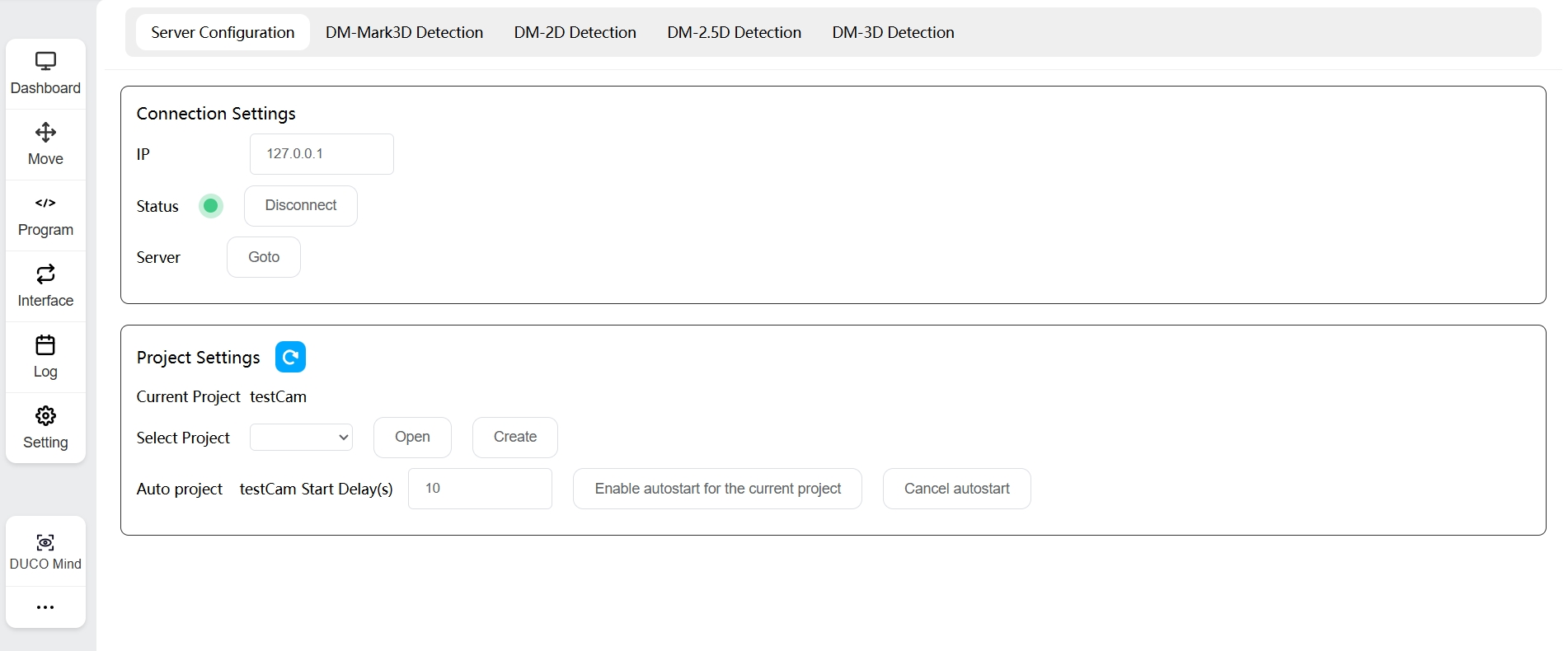
Process#
In DUCOCORE, create a process as shown below.
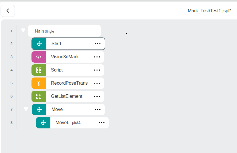
Create a global variable of the pose type named g_pose, a local variable of the pose type named pose_out, and a pose_list type variable named list. In the Vision3dMark process, select the process created in the previous step, and set the variable to pose_out.
In the Script, enter the following script:
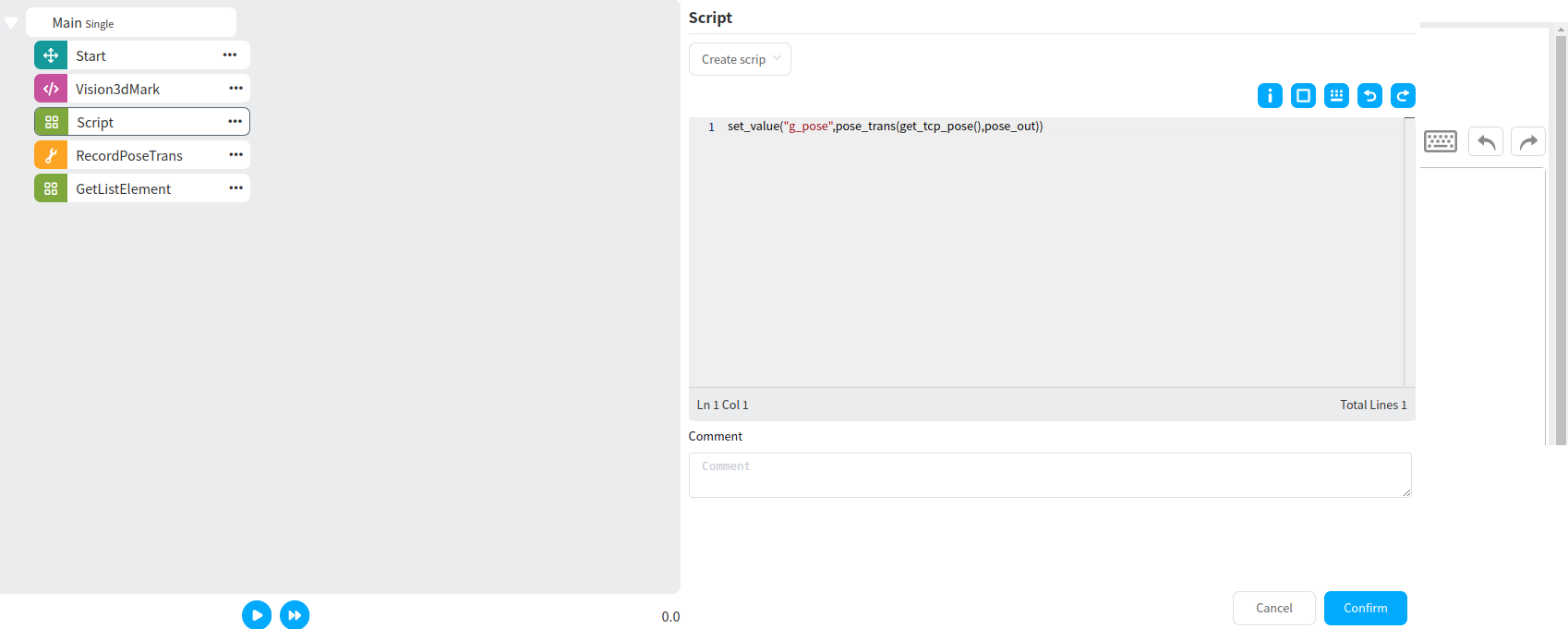
Tip
Since the newly created g_pose does not have a value, you need to run the program once to get the value before proceeding to the next step, where g_pose will be set as the reference.
Double-click RecordPoseTrans, set g_pose as the reference, and set Output - Transformed Pose to list. Then click Teach Add. You can add as many teaching points as needed. The image below shows the addition of one teaching point.
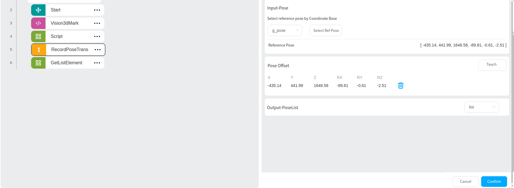
Tip
The number of teaching points added determines the number of GetListElement blocks. The value of GetListElement corresponds to the pick point.
Create a local variable of the pose type named pick1, and in the GetListElement block, assign the first value of list to pick1. At this point, pick1 will be the first pick point. Then add a MoveL block to move to pick1, as shown below.
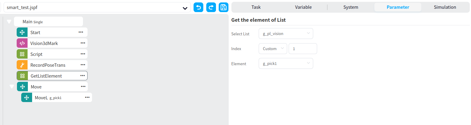
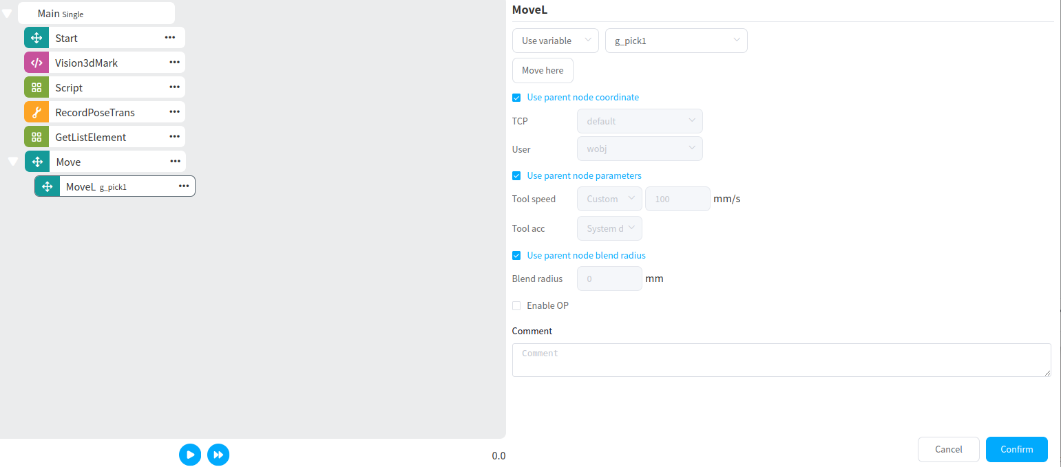
Tip
The image above shows the program for adding one teaching point. To add more teaching points, simply click Teach Add multiple times in the RecordPoseTrans block.
Accuracy Verification SOP#
- Description of Accuracy Anomaly
Significant deviation in actual on-site pick accuracy.
Large errors in accuracy verification tool results.
X direction exceeds 0.5, Y direction exceeds 0.5, Z direction exceeds 0.5, RX direction exceeds 0.1, RY direction exceeds 0.1, RZ direction exceeds 0.1.
1. Check Camera Point Cloud Completeness and Quality#
- <1>. Check if the camera parameter settings are reasonable.
Verify that the camera parameters are not causing overexposure ( Exposure is generally set to 3000-5000). Overexposure results in missing point cloud data in the central area.
- <2>. Check if the camera’s working space is within the calibration space.
Typically, hand-eye calibration is performed within a 420 - 550 working space, so the working space should also be within this range.
2. Check the Matching Algorithm Output#
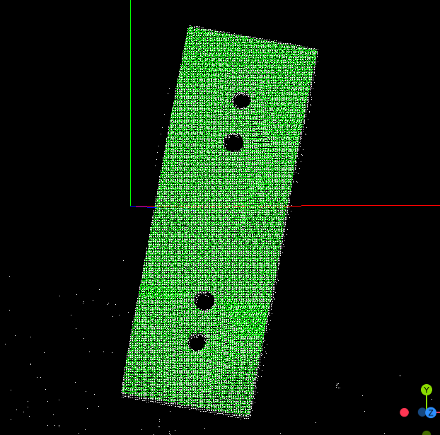
<1>. Check the Debug3D result of the fine matching operator in the process.
A correct matching result is shown below ( Green is the template and it completely overlaps with the point cloud to be matched (white)).
Caution
If the template point cloud does not completely overlap with the point cloud to be matched, improve the matching results from two aspects:
First, create a high-quality template.
Second, adjust the coarse matching and fine matching parameters.
Ensure that the matching reaches an optimal state before proceeding with grabbing or other application operations.
- <2>. Strategies for Creating a High-Quality Template
Ensure the template point cloud is complete, with clear edges and minimal noise near the edges.
- <3>. Coarse Matching Parameter Adjustment Strategy
Adjust the
Point Cloud Voxel Sampling ValueandScene Point Cloud Voxel Sampling Valueto smaller values. However, keep these two parameters consistent.Increase the
Scene Point Cloud Skip Sampling Rateto ensure the Debug3D result of the coarse matching operator is relatively stable and the matching effect is good.
- <4>. Fine Matching Parameter Adjustment Strategy
Increase the
Classic Template Point Cloud Voxel Sampling RateandClassic Scene Point Cloud Voxel Sampling Rate(usually set to 20-30), and keep these two values consistent. After setting, check whether the fine matching result improves.
3. Hand-Eye Calibration Accuracy Check#
- <1>. Check whether the calibration board/sphere was centered in the camera’s field of view during the initial calibration.
Ensure that the camera image is clear. Check this by verifying the camera’s parameter settings. The parameters should not cause overexposure, and the camera’s working space should be appropriate.
- <2>. Check whether the automatic calibration parameters are set reasonably.
Ensure the robot’s motion space during automatic calibration includes the actual working space used in the application. If it does not, adjust the automatic calibration parameters and recalibrate. You may need to increase the automatic calibration parameters slightly.
Tip
The automatic calibration parameters should not be set too large initially for two reasons:
The robot’s pose might be restricted, and the robot may not be able to reach the generated poses.
If the robot moves too far, the camera may not capture the calibration board/sphere, so the automatic calibration parameters need to be fine-tuned gradually.
- <3>. Check the error results from the calibration calculation.
If 80% or more of the errors are within 1mm, the calibration is acceptable. If some errors are as high as several millimeters, check both camera accuracy and robot movement accuracy.
4. Camera Accuracy Check#
<1>. Ensure the calibration block remains stationary while the robot moves.
<2>. Ensure the calibration block’s template is high-quality, and that the coarse matching and fine matching parameters are optimized.
<3>. Move the robot along the X direction, moving only the robot’s X value by a fixed amount (this value depends on the site, but ensure that the camera can capture the entire calibration block before and after the movement; otherwise, the value is too large).
<4>. Record the 3D positions before and after the robot moves, and also record the pose of the calibration block recognized before and after the move.
<5>. Calculate the distance between the robot’s 3D positions before and after the move, and the distance between the recognized 3D positions of the calibration block (in x, y, z). Calculate the difference between these two distances.
<6>. Repeat the above steps (1-5) for the Y and Z directions. If the difference in each direction is less than 0.5mm, replace the camera and run the test again. If the result remains the same, check the robot’s movement accuracy. Otherwise, replace the camera and recalibrate using the accuracy verification tool.
5. Robot Movement Accuracy Check#
<1>. Coordinate with the staff to check the robot’s movement accuracy.
<2>. After recalibrating the robot, rerun the accuracy verification using the calibration tool.
6. Accuracy Verification Tool#
Used to calculate the accuracy error after the camera and the mark block move by a certain distance.
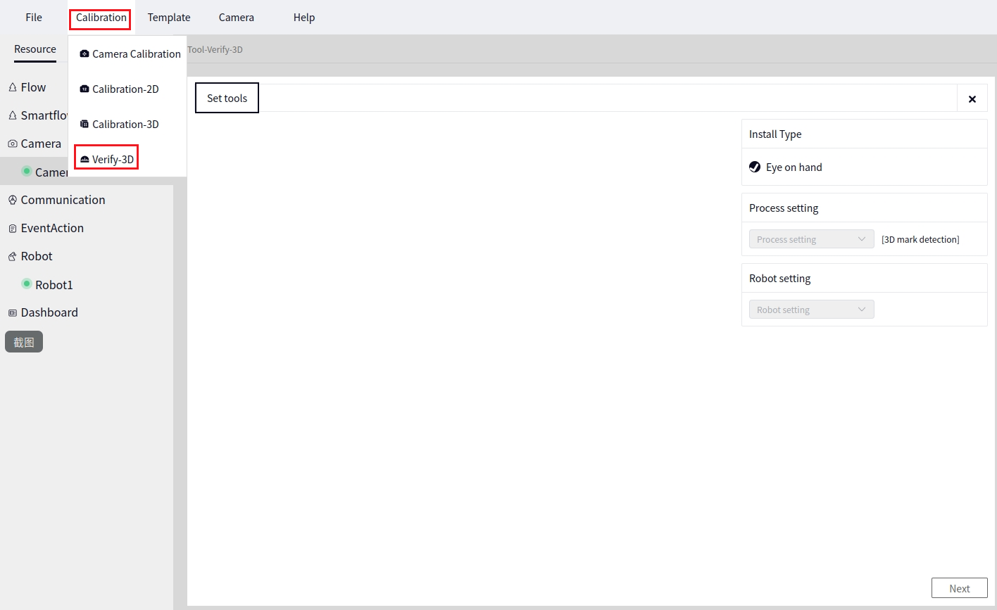
Entry Point#
Click Calibration->Verify-3D, as shown below.
Tool Setup#
Process Setup
Select the
3D Mark Block Positioning Processused for recognition.
Robot Setup
Select the connected robot.
After setting up the tool, click Next to proceed to the following interface.
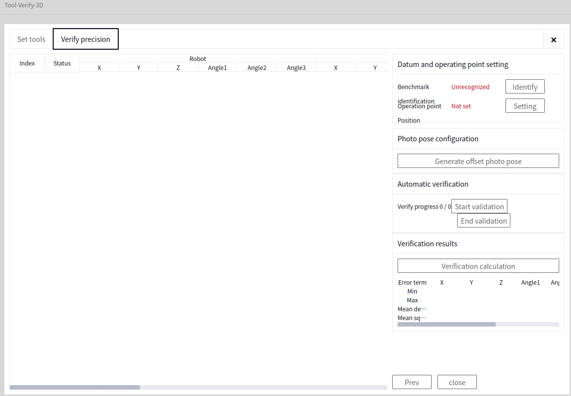
Reference Recognition#
Position the camera in the normal mark block recognition position and click the identify button. The software will automatically call the 3D Mark Block Positioning Process. A pop-up will appear indicating whether recognition was successful. The image below shows a successful recognition.
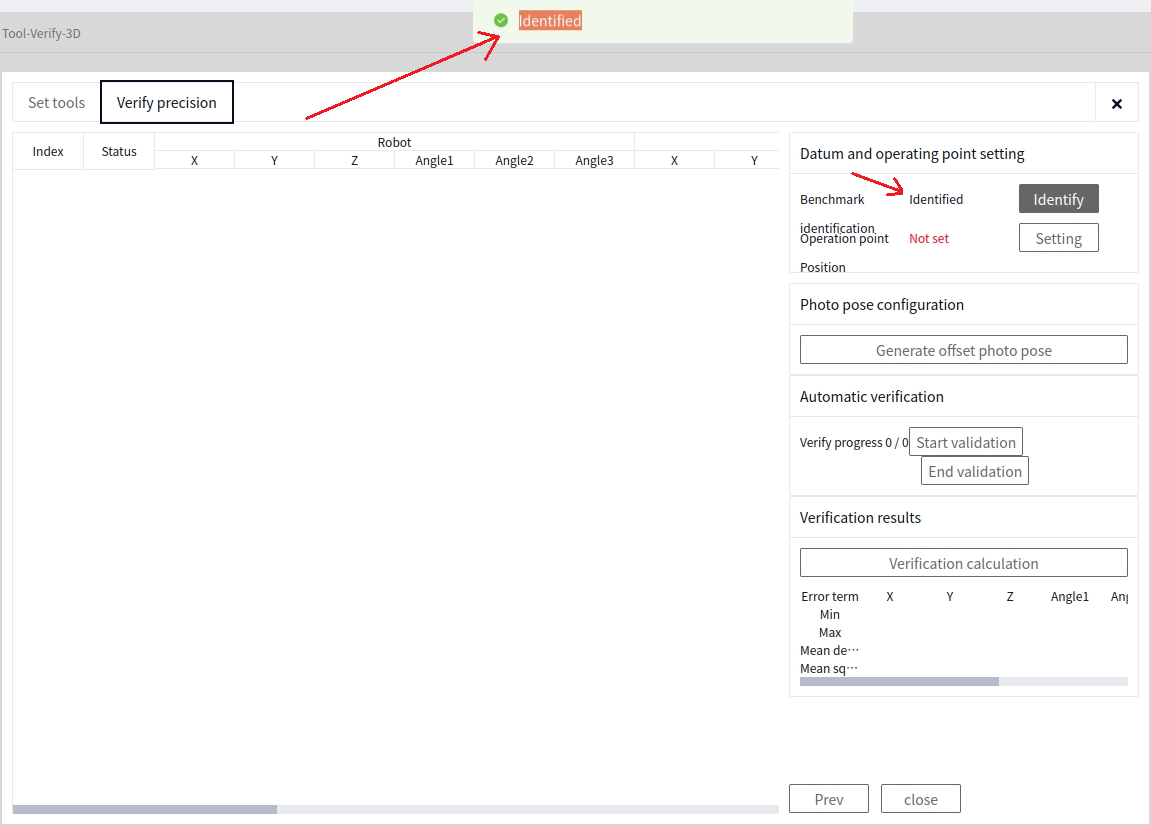
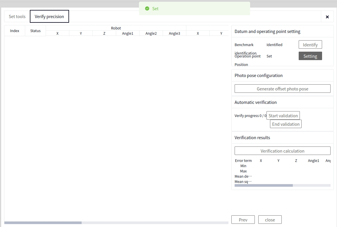
Operation Point Pose#
This function sets a teaching point. Switch to the DucoCore robot interface, move the robot to a teaching point, and then switch back to the DucoMind interface. The image below shows a successful setup.
Generate Capture Offset Poses#
Click the Generating posture button to enter the following interface, as shown below.
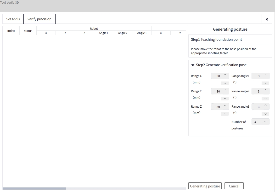
- The image above shows the interface for setting the parameters for generating poses, including:
X Range: The X range for the robot to move based on the current recognition pose (moveTCP).
Y Range: The Y range for the robot to move based on the current recognition pose (moveTCP).
Z Range: The Z range for the robot to move based on the current recognition pose (moveTCP).
Angle 1 Range: The RX range for the robot to move based on the current recognition pose (moveTCP).
Angle 2 Range: The RY range for the robot to move based on the current recognition pose (moveTCP).
Angle 3 Range: The RZ range for the robot to move based on the current recognition pose (moveTCP).
Pose Count: The total number of poses to generate.
Tip
After setting the xyz and angle parameters, the program automatically generates positive and negative ranges.
After setting the parameters, click the Generate Posture button.
Automatic Verification#
Click Start Verification to begin automatic verification from the first row of data. Click Stop Verification to halt the verification process. The verification results will be displayed in the status column of each row.
Verification Calculation#
Click the Verification Calculation button to calculate the Error, Mean, and Variance for all the data. The error includes the Maximum and Minimum values.
DM-Mark2D Marker Board Pose Correction Application#
Create a New Project#
Open the DUCOMIND webpage. If the controller’s IP address is known, you can use another laptop or computer to open the DUCOMIND webpage, provided that the device’s network is set to the same subnet as the controller. For example, if the controller’s IP is 192.168.3.10, visit 192.168.3.10:7300.
For more details, refer to: Software Operation Guide->Project Management->Create New Project
After opening the DUCOMIND webpage, if a project has already been created, you can directly click the project name, and the Open option will appear. Click Open to open the corresponding project. The following image shows the effect after clicking the first project.
If you want to create a new project, just click Create New Project, as shown below.
After clicking Create New Project, the following interface will pop up. Enter the relevant information.
Camera#
For more details, refer to: Software Operation Guide->Camera Management->Create New Camera and Software Operation Guide->Camera Management->Camera Configuration->DM-Cam2D Camera
Hardware Introduction#
Introduction to Vision Tools#
Vision Option Package List#
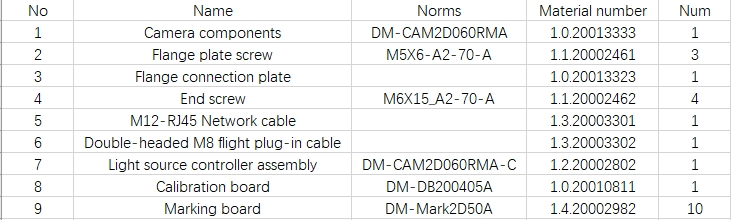
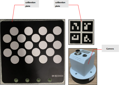
Camera Installation Diagram#
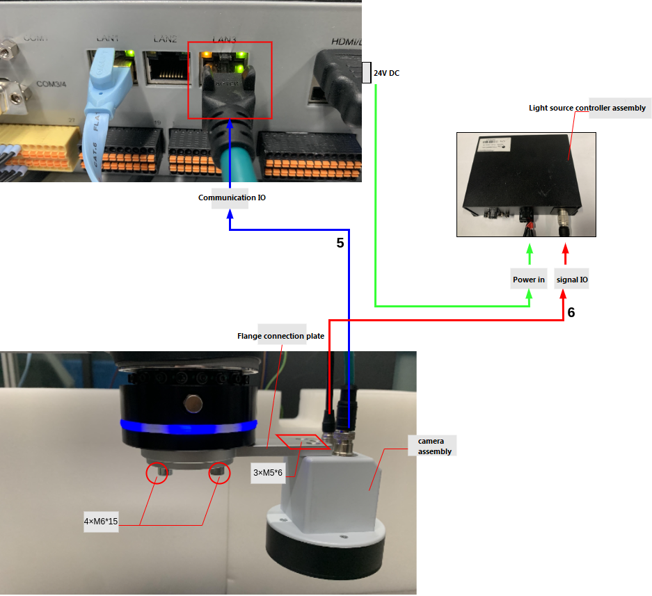
Tip
Connect the camera assembly to the flange connection plate using 3 flange plate screws, then attach it to the robot’s flange using 4 end screws.
Connect the two ports (communication port, power, and trigger port) on the camera assembly using cables (M12-RJ45 network cable, double-headed M8 aviation plug cable).
Connect the M12-RJ45 network cable to the industrial computer’s RJ45 network port.
Connect the double-headed M8 aviation plug cable to the power signal output port of the light source controller assembly.
Connect the power input port of the light source controller assembly to the robot’s 24V output port.
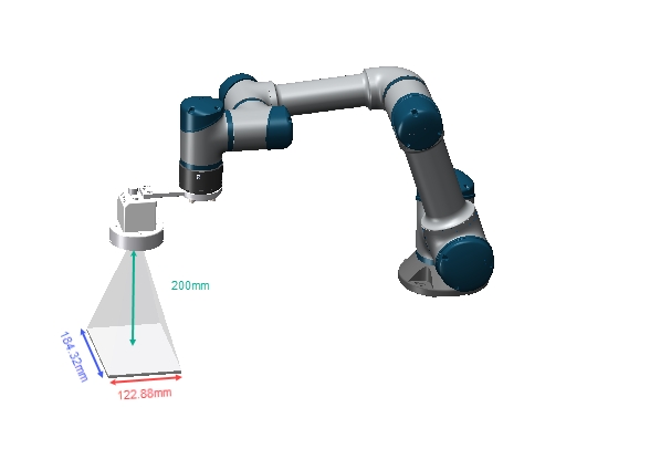
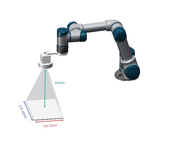
Camera Field of View Diagram#
At photo heights of 200mm and 300mm, the camera’s field of view is as shown below:
Light Source Adjustment Instructions#
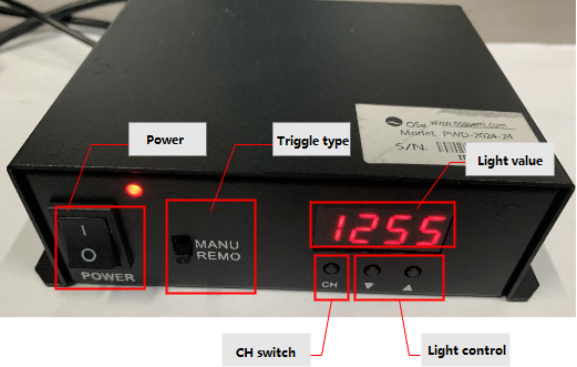
Tip
The power switch is used to control the power supply for the light source and the camera.
The trigger type is set to [REMO] mode by default, which allows the light source to be triggered by the camera’s software trigger mode. [MANU] mode keeps the light source constant.
Use the channel switch button to toggle between channel 1 and channel 2 of the light source. The brightness adjustment button can adjust the brightness value, with higher values making the light brighter. The brightness value is displayed on the LED.
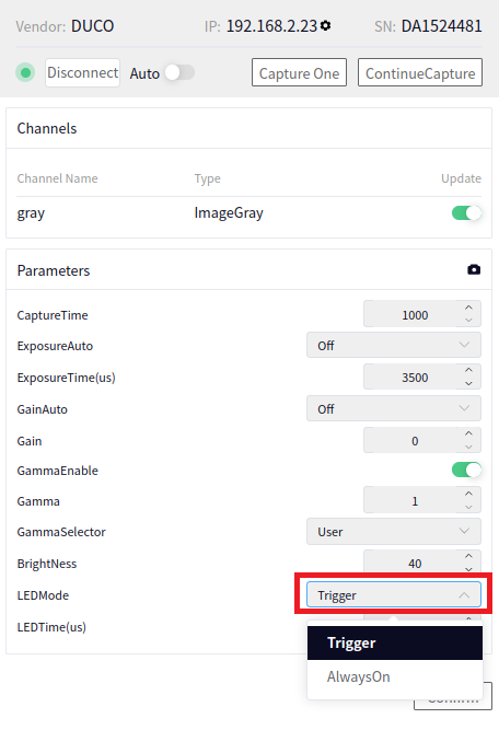
Tip
The usage of the trigger type should be combined with the camera configuration parameters shown above: trigger/constant light software operation.
Camera Network Cable Connection#
Simply plug the camera’s network cable into the controller’s network port (no configuration needed), but it is recommended to connect the camera’s network cable to the controller first to establish the connection.
Camera Power Cable Connection#
Caution
After connecting the camera’s power and network cables, the camera’s indicator light should turn blue, and the indicator light on the controller’s network port should flash normally, indicating a proper connection. Otherwise, check the cables for issues.
Create a New Camera#
Open the newly created project or an existing project, and create a DM-Cam2D. Please refer to the following.
As shown in the image below, click the area indicated to pop up the DM-Cam2D interface. Select DM-Cam2D as the camera model.
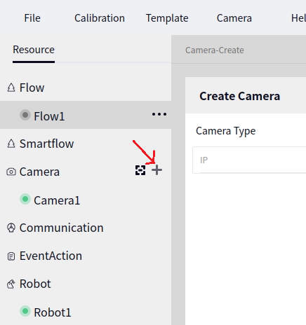
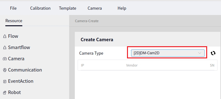
After selecting the camera model, click the scan button indicated by the arrow below to scan for the DM-Cam2D in the connected devices.
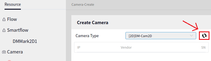
Tip
Before connecting the camera, you can use the Dahua Mv viewer to check the camera’s IP. After clicking scan, it may take a few seconds for the results to appear.
Once the DM-Cam2D is detected, click the + next to the detected camera information to create a new camera, as shown below:
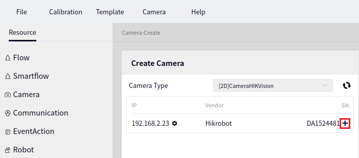
After creating the new camera, the first camera’s default name will be Camera 1. Click Camera 1 to display the camera configuration interface, as shown below:
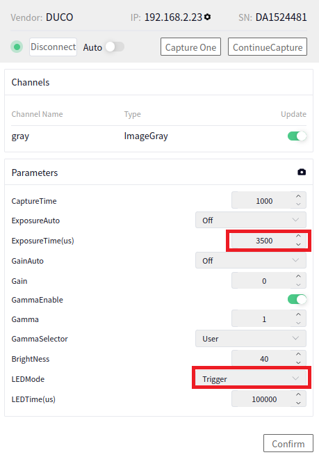
Connect the Camera#
After clicking the Connect button, the system will attempt to connect to the DM-Cam2D. It usually takes a few seconds to connect successfully. Once connected, the Connect button will change to a Disconnect button.
Tip
The DM-Cam2D is a POE camera. After connecting to the device, clicking connect will allow you to set the camera to auto-connect, so the camera will connect automatically every time the project is opened.
If the camera fails to connect, an error window will pop up. In this case, check whether the network cable and camera are intact, or if there is insufficient power supply.
Camera Adjustment#
When adjusting the focal length, you need to turn the bottom screw of the lens. To adjust the focal length correctly, refer to the correct focal length image in the table below.
Focal Length Adjustment Result Image |
Example: Image |
|---|---|
Incorrect Focal Length Image |
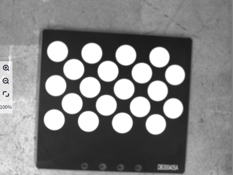
|
Correct Focal Length Image |
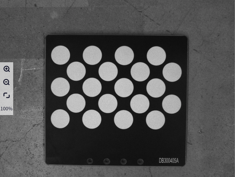
|
When adjusting the aperture, turn the top screw of the lens. To adjust the aperture correctly, refer to the correct aperture image in the table below.
Aperture Adjustment Result Image |
Example: Image |
|---|---|
Incorrect Aperture Image (Too Bright) |
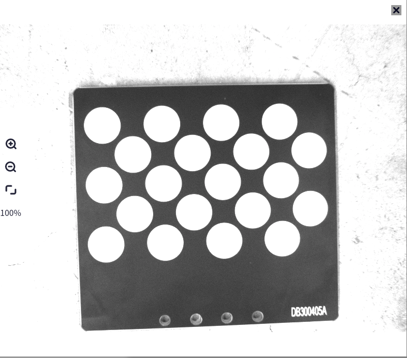
|
Incorrect Aperture Image (Too Dark) |
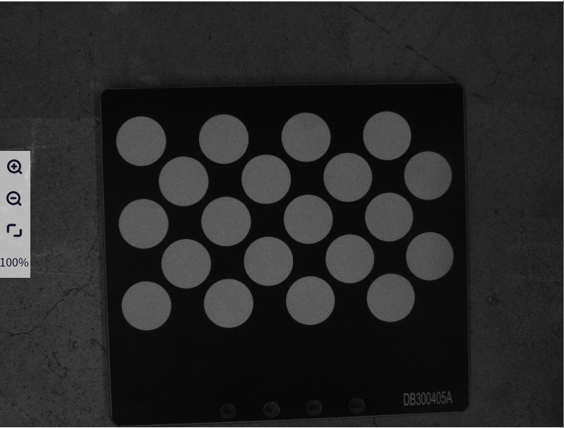
|
Correct Aperture Image |
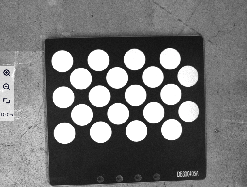
|
When adjusting the camera’s focal length and aperture, keep the following issues in mind:
Tip
Before adjusting the camera’s focal length and aperture, determine the camera’s working height. Once the working height is determined, adjust the camera’s focal length and aperture accordingly.
Before adjusting the camera parameters, adjust the camera’s focal length first, then adjust the aperture. Generally, the focal length and aperture are pre-adjusted when shipped, but if the images are unclear, manual adjustments may be needed.
When adjusting the camera’s focal length and aperture, you can also refer to tools for adjusting the camera’s focal length and brightness.
These adjustments should be made in conjunction with the light source. Ensure the light source is on before making adjustments.
Parameter Configuration#
The image below shows the parameter configuration interface for the DM-Cam2D camera.
Tip
The most commonly configured parameters are exposure and gain.
Exposure: If the camera image is too bright or too dark, adjust this parameter (note: when the light source is on, exposure should not be set too high to avoid overexposure). You can use the built-in Dahua software to set auto exposure, record the exposure value, and input it into the connected camera’s configuration interface.
Gain: You can use the built-in Dahua software to set auto gain, record the gain value, and input it into the connected camera’s configuration interface.
After setting the parameters, click the confirm button to apply the changes.
Robot#
For more details, refer to: Software Operation Guide->Robot Management->Create New Robot
Create a New Robot#
Click the area indicated by the arrow below to pop up the new robot interface.
Tip
The robot model supports two types: ducocore_gcr10 and ducocore_gcr5.
Click the Create button to create a new robot.
Connect the Robot#
Click the newly created robot’s name to pop up the robot configuration interface. Enter the robot’s IP and click the Connect button to connect the robot. Once connected, the Connect button will change to Disconnect, and the dot in front of the connection will turn from red to green, as shown below:
DM-Mark2D Pose Correction#
Select Resources->Intelligent Process, and click the plus sign in the upper left corner of the intelligent process to add the DM-Mark2D pose correction block.
Basic Settings#
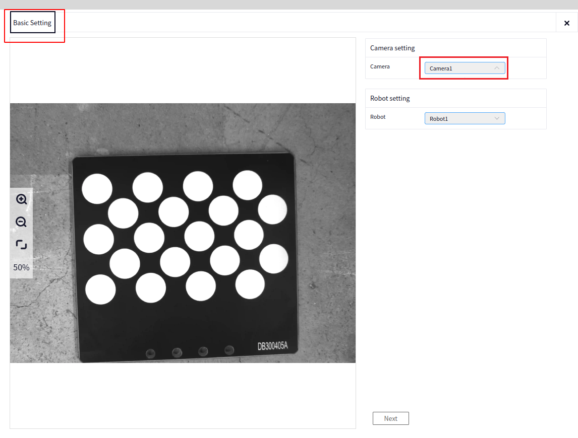
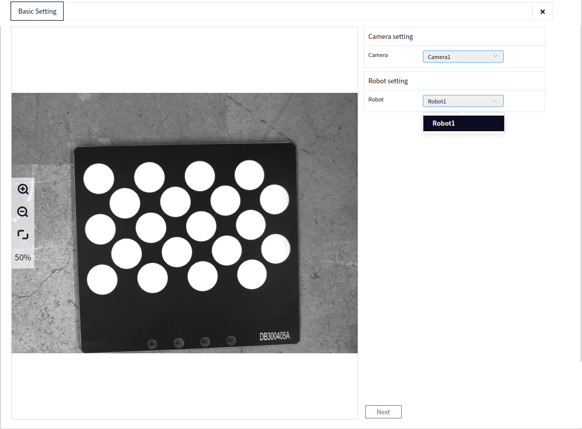
Camera Configuration: Click Camera and select the connected 2D camera (currently, this block configures Hikvision cameras).
Robot Configuration: Select the connected robot, then proceed to the next step.
Auto Calibration#
Teaching the Photo Pose#
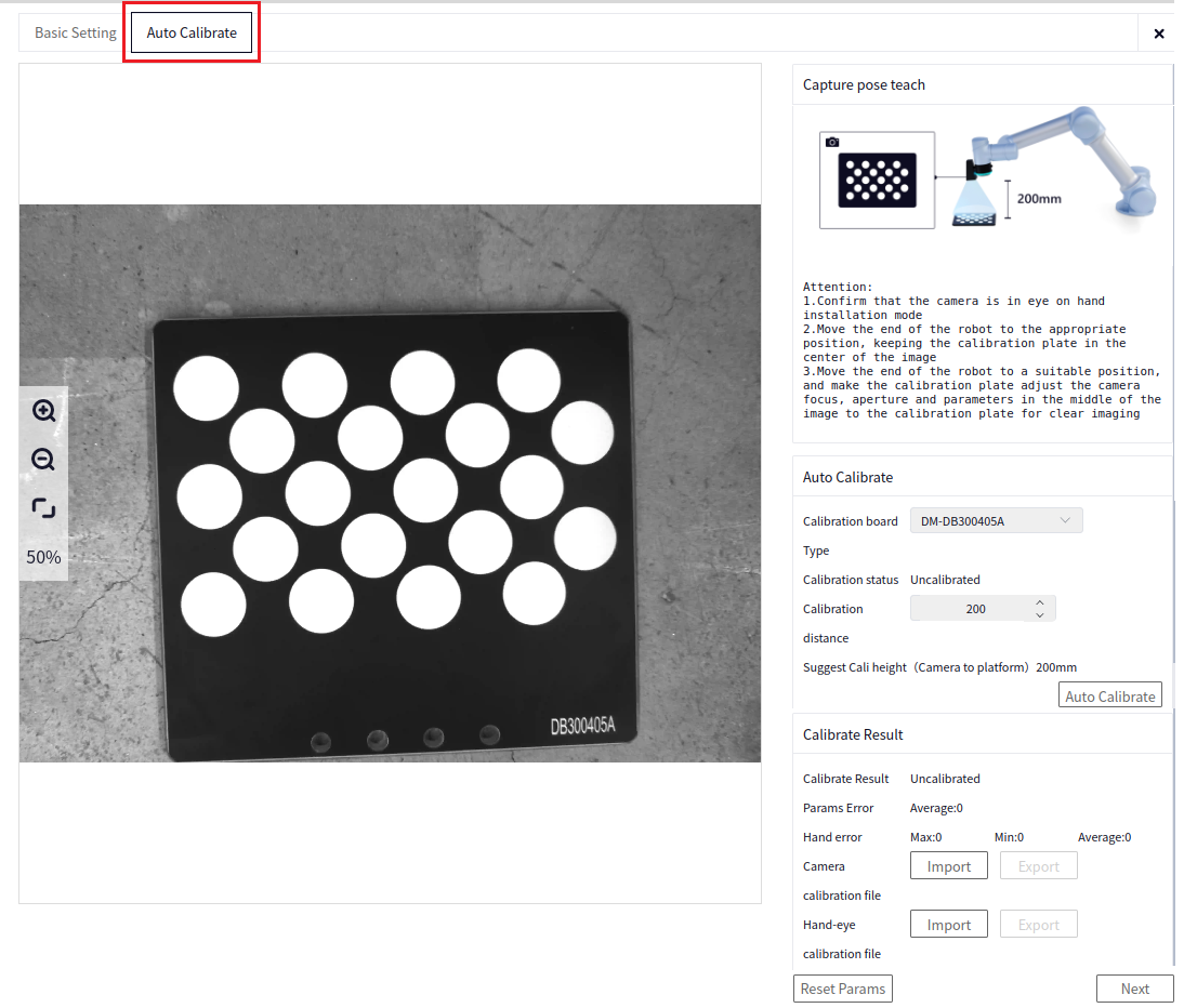
Before performing auto calibration, check the following points:
Tip
Confirm that the camera is installed in the eye-in-hand configuration.
Move the robot’s end to the appropriate position ( end leveling, i.e., Rx=180, Ry=0), ensuring the calibration board is centered in the image. The recommended calibration distance is 200mm.
Adjust the camera’s focal length, aperture, and parameters to ensure a clear image of the calibration board.
Auto Calibration#
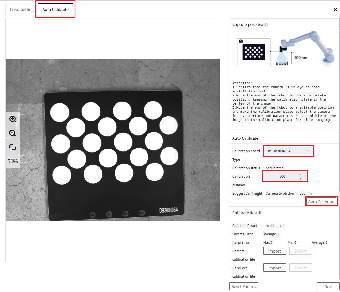
Calibration Board Type: Select the DM-DB300405A type calibration board (included in the process package).
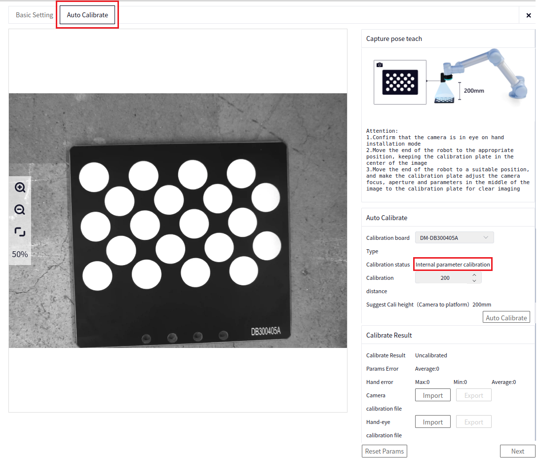
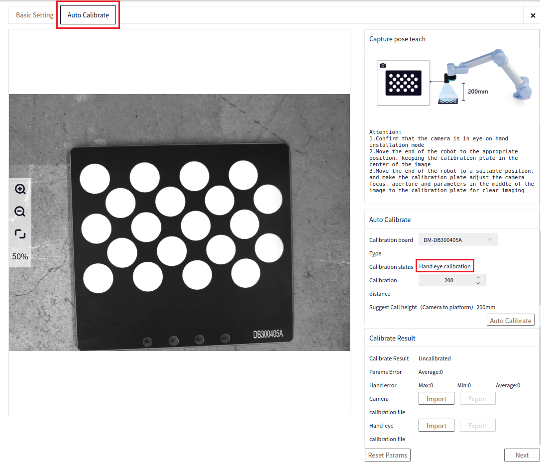
Calibration Status: Default is automatic.
Calibration Distance: Enter the height from the marker board to the camera (in mm).
Intrinsic Parameter File Export/Import: Supports exporting and importing the intrinsic parameter calibration files of the intelligent block.
Hand-Eye File Export/Import: Supports exporting and importing the hand-eye calibration files of the intelligent block.
Click auto calibration to start the process. First, intrinsic parameter calibration will be performed. If successful on the first attempt, hand-eye calibration will automatically proceed. If the first intrinsic parameter calibration fails, the algorithm will attempt a second intrinsic calibration. If both attempts fail, check whether the camera exposure parameters are overexposed, and ensure that the camera height is not below 200mm.
Calibration Results#
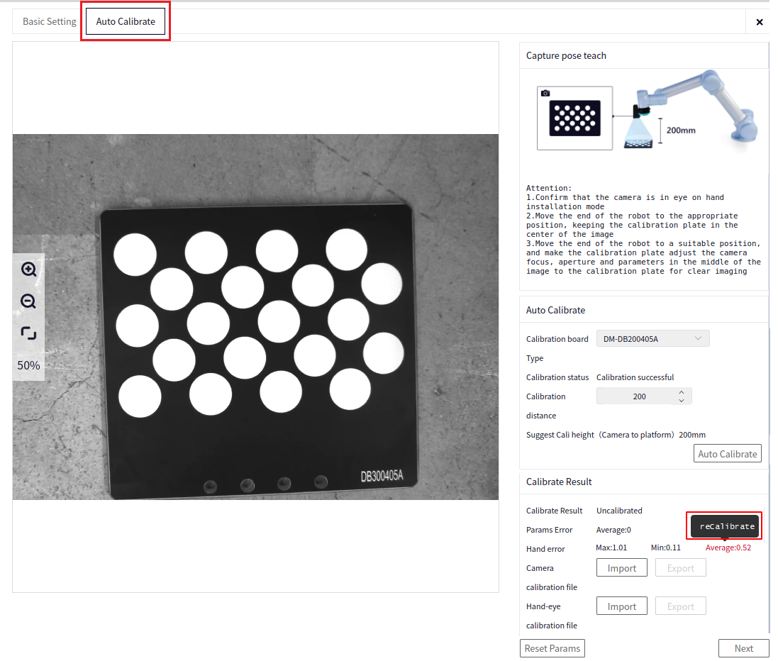
The projection error of the intrinsic calibration and the maximum, minimum, and average errors of the hand-eye calibration will be displayed on the interface. Click next to proceed to the reference setting interface.
Intrinsic Calibration Error: If the intrinsic error exceeds 0.7, it is recommended to readjust the camera exposure and the position of the calibration board in the camera’s center, and recalibrate the intrinsic and hand-eye parameters.
Hand-Eye Calibration Error: If the maximum error exceeds 0.9, or the average error exceeds 0.5, it is recommended to readjust the camera exposure, the position of the calibration board in the camera’s center, and verify the distance between the camera and the calibration board before recalibrating the intrinsic and hand-eye parameters.
Reference Settings#
Teaching the Reference Pose#
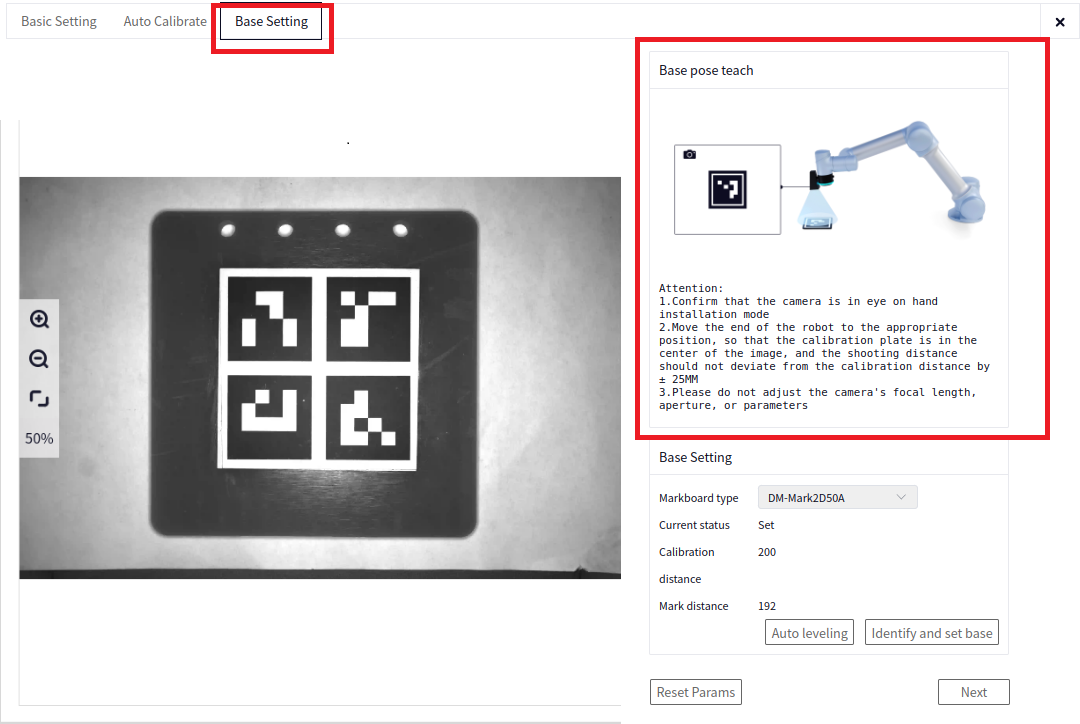
Before setting the reference pose, check the following points:
Tip
Confirm that the camera is installed in the eye-in-hand configuration.
Move the robot’s end to the appropriate position ( end leveling, i.e., Rx=180, Ry=0), ensuring the 2DMark marker board is centered in the image. It is recommended that the shooting distance does not deviate more than 25mm from the calibration distance.
Do not adjust the camera’s focal length, aperture, or parameters.
Reference Configuration#
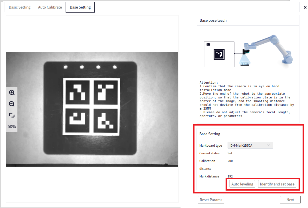
Marker Board Type: Select DM-Mark2D50A Marker Board or Custom DM-Mark2D. When selecting Custom DM-Mark2D, you need to input the DM-Mark2D dimensions in mm.
Current Status: The default is unset. When you click Identify and Set Base/Auto Leveling, the status will change to set.
Calibration Distance: This is the distance between the calibration board and the camera entered during auto calibration.
Marker Distance: After auto calibration, the distance between the marker board and the camera is calculated. If the marker distance exceeds the calibration distance by more than 25mm, the interface will display Too Far. If the accuracy is sufficient, you can ignore this; otherwise, adjust the calibration distance and recalibrate.
Auto Leveling: This function ensures that the camera plane remains parallel to the marker board plane. It is recommended not to use this button unless required ( if the end is level and parallel to the work plane, it is recommended not to click; if you must use it, do so within 100mm of the work plane). If clicked, you need to click Identify and Set Reference to record the reference pose.
Identify and Set Reference: Identify the marker board and record the pose of the marker board at this time for pose correction. After setting, click next to enter the pose correction interface.
Pose Correction#
Correction Configuration#
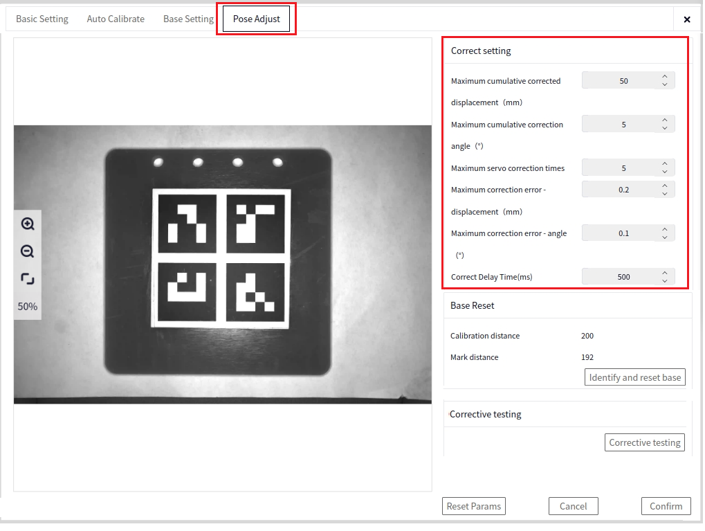
Maximum Cumulative Correction Displacement (mm): During correction, the cumulative distance moved by the robot. If the cumulative distance exceeds the maximum cumulative correction displacement, the correction process will terminate, and correction will end.
Maximum Cumulative Correction Angle (°): During correction, the cumulative angle moved by the robot. If the cumulative angle exceeds the maximum cumulative correction angle, the correction process will terminate, and correction will end.
Maximum Servo Correction Attempts: During correction, the cumulative number of movements by the robot. If the cumulative number of movements exceeds the maximum servo correction attempts, the correction process will terminate, and correction will end.
Termination Condition - Displacement Error (mm): During correction, if the displacement deviation between the identified marker board pose and the reference recorded pose is less than the termination condition, and the angle error termination condition is also met, the correction process will terminate, and correction will end.
Termination Condition - Angle Error (°): During correction, if the angle deviation between the identified marker board pose and the reference recorded pose is less than the termination condition, and the displacement error termination condition is also met, the correction process will terminate, and correction will end.
Pose Adjustment Delay (ms): To prevent the robot from not stabilizing, which could affect the adjustment accuracy, a default delay of 500ms is applied.
Reset Reference#
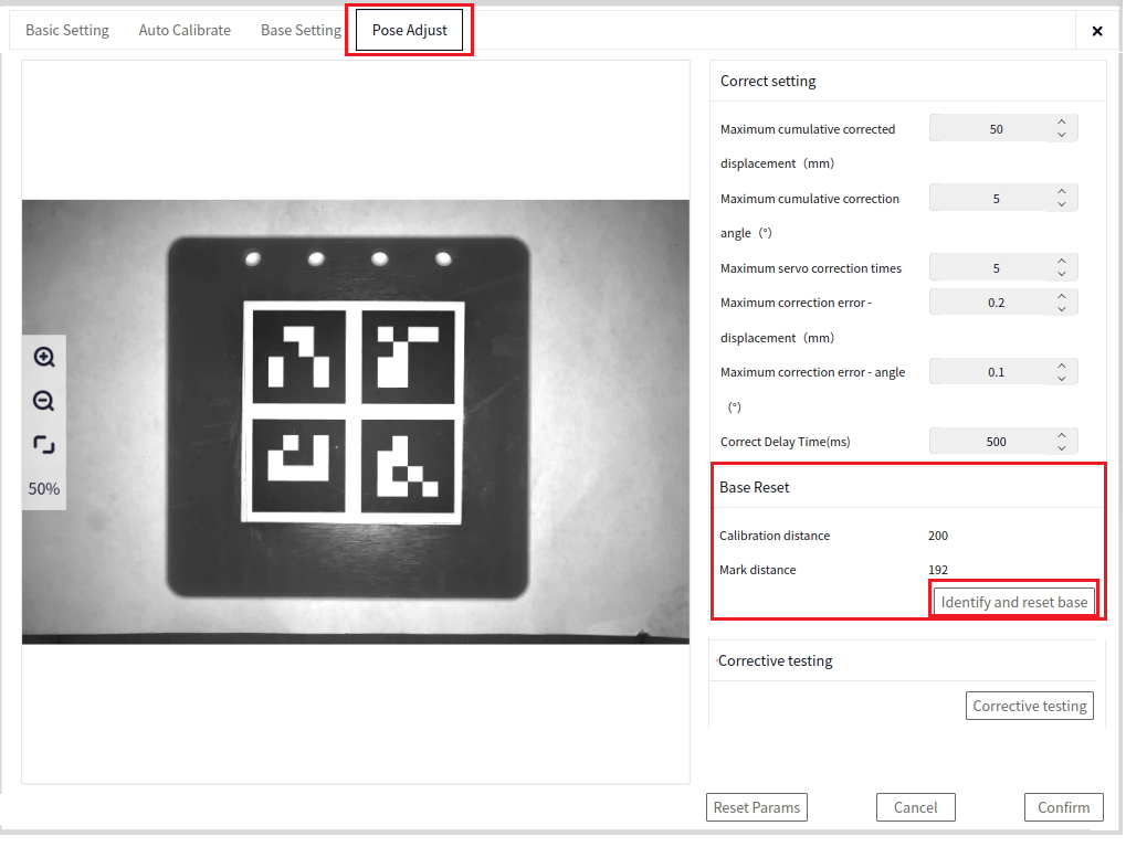
If the marker board has moved, or a new marker board is used, you need to reset the marker board reference. Otherwise, this step can be ignored if the marker board has not changed.
Calibration Distance: This is the distance between the calibration board and the camera entered during auto calibration.
Marker Distance: After auto calibration, the distance between the marker board and the camera is calculated.
Correction Test#
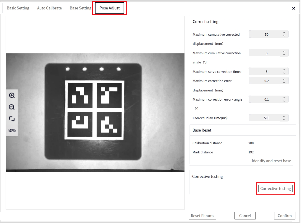
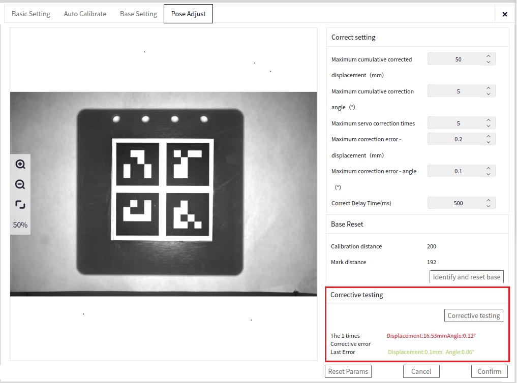
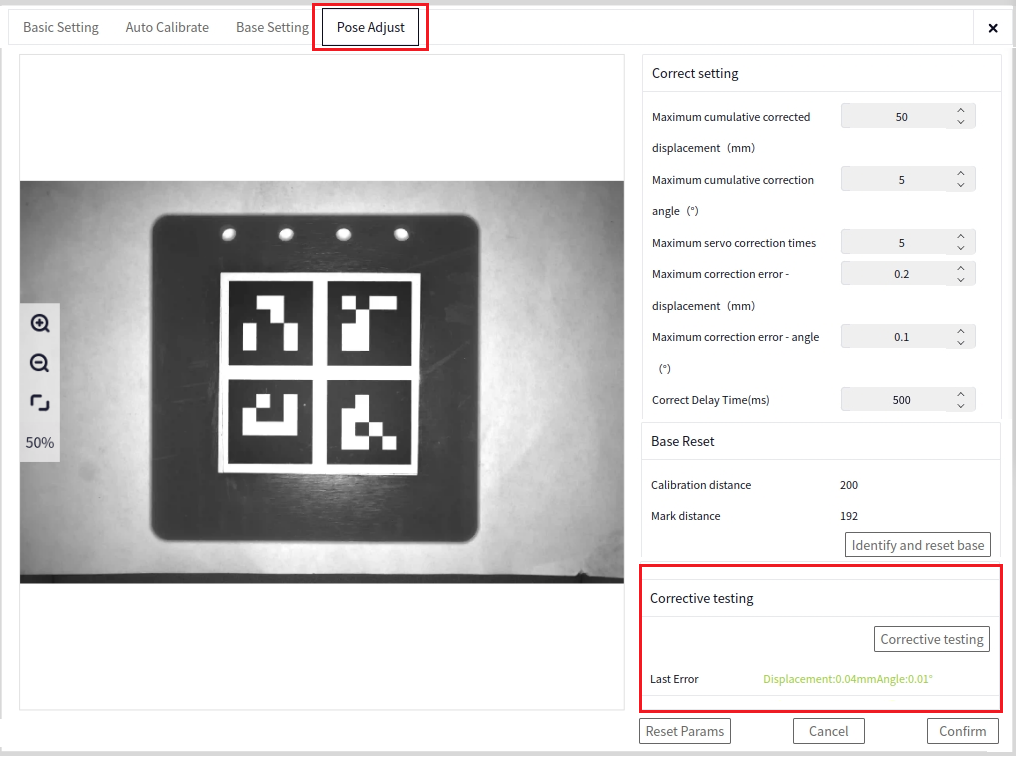
Correction Test: Click correction test to perform pose correction. The termination conditions for correction will be based on the correction configuration conditions set above (this can be used during the debugging phase).
Correction Error: Displays the displacement and angle corrected by the robot during each correction.
Reset All Parameters#
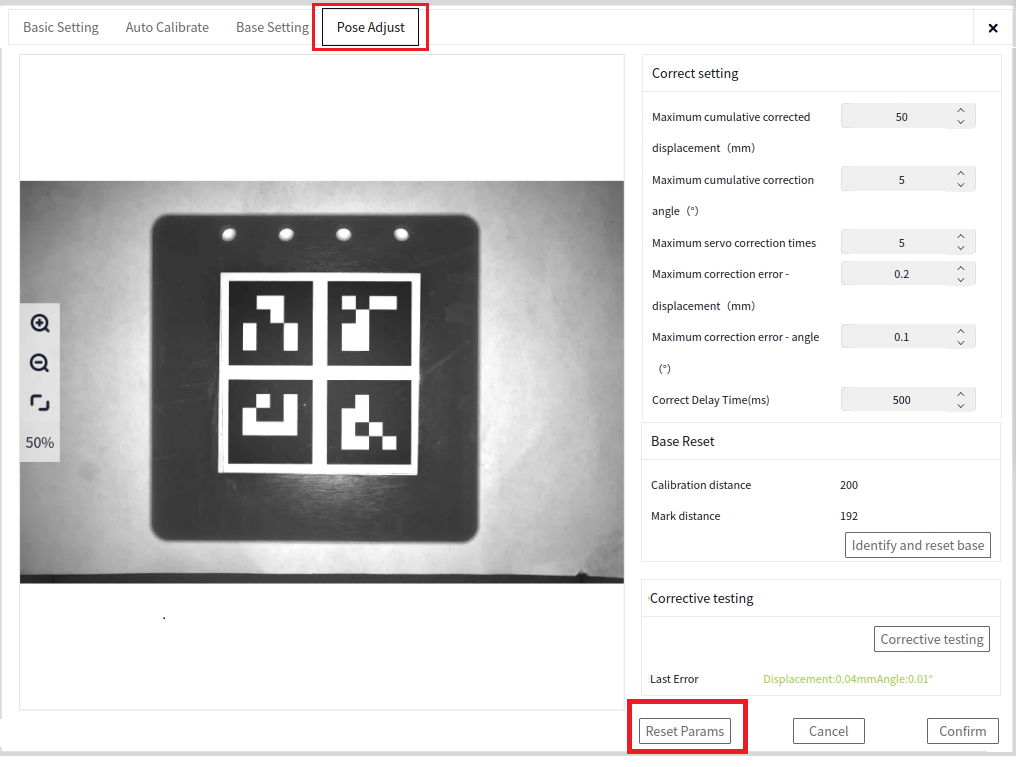
Resets all parameter configurations in the Basic Settings->Pose Correction interface, allowing you to reconfigure the intelligent block process.
Cancel#

Cancels all parameter settings in the Pose Correction interface. The correction configuration will revert to default values, and the reset reference will be canceled (if a reference reset was performed).
Confirm#
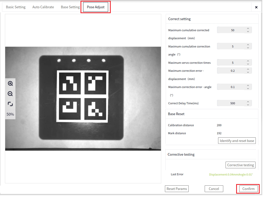
Saves all parameter configurations in the Basic Settings->Pose Correction interface for use in the robot-side configuration.
DUCO Core Side#
Vision Plugin#
Open the DUCO CORE interface, and click the area indicated by the arrow below to pop up the vision plugin interface. Enter the controller’s IP address and click connect.
Process#
In DUCOCORE, add the following process as shown below:
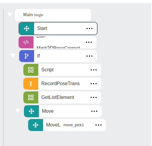
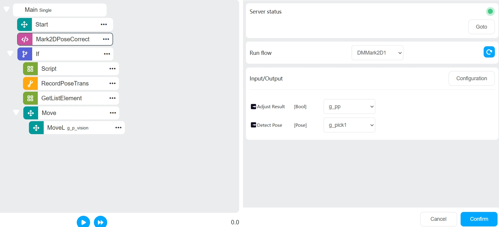
Create a local variable of pose type named mark_in_base (the pose of the marker board after correction recognition) and a Bool type variable named detect_success (whether the correction recognition was successful).
Configure the output in Mark2DPoseCorrect as shown below:
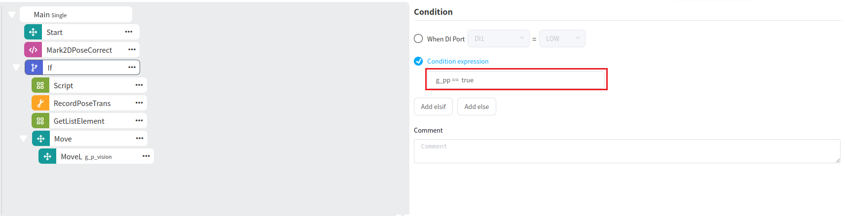
Add an If block. If the correction recognition is successful, proceed with the grabbing operation, as shown in the condition below:
Create a global variable of pose type named g_pose and a pose_list type variable named picklist.
In the Script block, enter the following script:
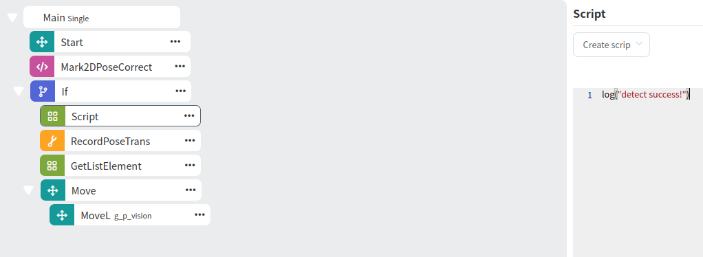
Tip
Since the newly created g_pose has no value, you need to run the program first to obtain the value before proceeding to the next step, where you will set g_pose as the reference.
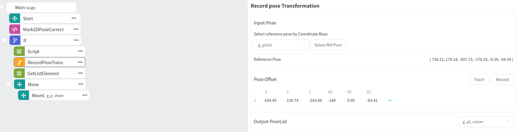
Double-click RecordPoseTrans, set g_pose as the reference, and set Output - Transformed Pose to picklist. Then click Teach Add to add the required number of teaching points. The following image shows the addition of one teaching point:
Tip
The number of teaching points added determines the number of GetListElement blocks. The value of GetListElement corresponds to the grabbing points.
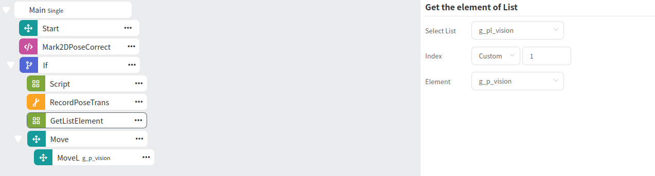
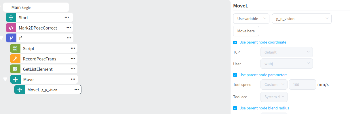
Create a local variable of pose type named move_pick1. In GetListElement, retrieve the first value from picklist and assign it to move_pick1. At this point, move_pick1 is the first grabbing point. Then, add a MoveL block, and move to move_pick1, as shown below:
Tip
The image above shows the program for adding one teaching point. If you need to add more teaching points, simply click Teach Add multiple times in RecordPoseTrans.
2D Target Positioning Application#
Create a New Project#
Open the DUCOMIND webpage. If the controller’s IP address is known, you can use another laptop or computer to open the DUCOMIND webpage, provided the network of the device is set to the same subnet as the controller. For example, if the controller’s IP is 192.168.3.10, visit 192.168.3.10:7300.
For more details, refer to: Software Operation Guide->Project Management->Create New Project
After opening the DUCOMIND webpage, if a project has already been created, you can directly click the project name, and the Open option will appear. Click Open to open the corresponding project. The following image shows the effect after clicking the first project.
If you want to create a new project, just click New Project, as shown below.
After clicking New Project, the following interface will pop up. Enter the relevant information.
Camera#
All 2D cameras in the camera list are supported for connection. When connecting different cameras, please refer to the manual of the respective camera brand. The following section provides a detailed introduction to the hardware installation and setup of the Cam2D camera.
For more details, refer to: Software Operation Guide->Camera Management->Create New Camera and Software Operation Guide->Camera Management->Camera Configuration->DM-Cam2D Camera
Hardware Introduction#
Tip
Connect the camera assembly to the flange connection plate using 3 flange plate screws, then attach it to the robot’s flange using 4 end screws.
Connect the two ports (communication port, power, and trigger port) on the camera assembly using cables (M12-RJ45 network cable, double-headed M8 aviation plug cable).
Connect the M12-RJ45 network cable to the industrial computer’s RJ45 network port.
Connect the double-headed M8 aviation plug cable to the power signal output port of the light source controller assembly.
Connect the power input port of the light source controller assembly to the robot’s 24V output port.
At photo heights of 200mm and 300mm, the camera’s field of view is as shown below:
Tip
The power is used to control the power supply for the light source and the camera.
The trigger type is set to [REMO] mode by default, allowing the light source to be triggered by the camera’s software trigger mode. [MANU] mode keeps the light source constant.
Use the channel switch to toggle between channel 1 and channel 2 of the light source. The light control can adjust the brightness value, with higher values making the light brighter. The brightness value is displayed on the LED.
Tip
The usage of the trigger should be combined with the camera configuration parameters shown above: Trigger/AlwaysOn light software operation.
Camera Network Cable Connection#
Simply plug the camera’s network cable into the controller’s network port (no configuration needed), but it is recommended to connect the camera’s network cable to the controller first to establish the connection.
Camera Power Cable Connection#
Caution
After connecting the camera’s power and network cables, the camera’s indicator light should turn blue, and the indicator light on the controller’s network port should flash normally, indicating a proper connection. Otherwise, check the cables for issues.
Create a New Camera#
Open the newly created project or an existing project, and create a DM-Cam2D. Please refer to the following.
As shown in the image below, click the area indicated to pop up the DM-Cam2D interface. Select DM-Cam2D as the camera model.
After selecting the camera model, click the scan button indicated by the arrow below to scan for the DM-Cam2D in the connected devices.
Tip
Before connecting the camera, you can use the Dahua Mv viewer to check the camera’s IP. After clicking scan, it may take a few seconds for the results to appear.
Once the DM-Cam2D is detected, click the + next to the detected camera information to create a new camera, as shown below:
After creating the new camera, the first camera’s default name will be Camera 1. Click Camera 1 to display the camera configuration interface, as shown below:
Connect the Camera#
After clicking the Connect button, the system will attempt to connect to the DM-Cam2D. It usually takes a few seconds to connect successfully. Once connected, the Connect button will change to Disconnect.
Tip
The DM-Cam2D is a POE camera. After connecting to the device, clicking connect will allow you to set the camera to auto-connect, so the camera will connect automatically every time the project is opened.
If the camera fails to connect, an error window will pop up. In this case, check whether the network cable and camera are intact, or if there is insufficient power supply.
Camera Adjustment#
When adjusting the focal length, you need to turn the bottom screw of the lens. To adjust the focal length correctly, refer to the correct focal length image in the table below.
Focal Length Adjustment Result Image |
Example: Image |
|---|---|
Incorrect Focal Length Image |
|
Correct Focal Length Image |
|
When adjusting the aperture, turn the top screw of the lens. To adjust the aperture correctly, refer to the correct aperture image in the table below.
Aperture Adjustment Result Image |
Example: Image |
|---|---|
Incorrect Aperture Image (Too Bright) |
|
Incorrect Aperture Image (Too Dark) |
|
Correct Aperture Image |
|
When adjusting the camera’s focal length and aperture, keep the following issues in mind:
Tip
Before adjusting the camera’s focal length and aperture, determine the camera’s working height. Once the working height is determined, adjust the camera’s focal length and aperture accordingly.
Before adjusting the camera parameters, adjust the camera’s focal length first, and then adjust the aperture. Generally, the focal length and aperture are pre-adjusted when shipped, but if the images are unclear, manual adjustments may be needed.
When adjusting the camera’s focal length and aperture, you can also refer to tools for adjusting the camera’s focal length and brightness for assistance.
These adjustments should be made in conjunction with the light source. Ensure the light source is on before making adjustments.
Parameter Configuration#
The image below shows the parameter configuration interface for the DM-Cam2D camera.
Tip
The most commonly configured parameters are exposure and gain.
Exposure: If the camera image is too bright or too dark, adjust this parameter (note: when the light source is on, exposure should not be set too high to avoid overexposure). You can use the built-in Dahua software to set auto exposure, record the exposure value, and input it into the connected camera’s configuration interface.
Gain: You can use the built-in Dahua software to set auto gain, record the gain value, and input it into the connected camera’s configuration interface.
After setting the parameters, click the confirm button to apply the changes.
Robot#
For more details, refer to: Software Operation Guide->Robot Management->Create New Robot
Create a New Robot#
Click the area indicated by the arrow below to pop up the new robot interface.
Tip
The robot model supports two types: ducocore_gcr10 and ducocore_gcr5.
Click the Create button to create a new robot.
Connect the Robot#
Click the newly created robot to pop up the robot configuration interface. Enter the robot’s IP and click the Connect button to connect the robot. Once connected, the Connect button will change to Disconnect, and the dot in front of the connection will turn from red to green, as shown below:
2D Target Positioning#
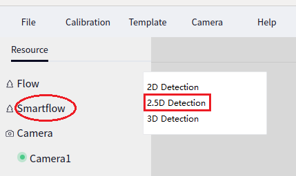
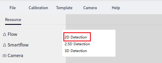
Select Resources->SmartFlow, and click the plus sign in the upper left corner of the SmartFlow to add the 2D Detection block.
Basic Settings#
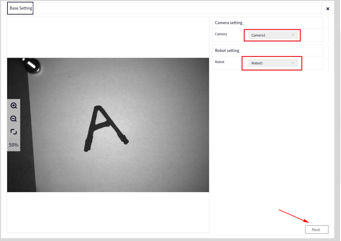
Camera Configuration: Click Camera and select the connected 2D camera. Only 2D cameras are supported here.
Robot Configuration: Select the robot and proceed to the next step.
Reference Registration#
Teaching the Photo Pose#
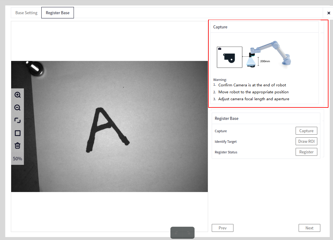
Before performing reference registration, check the following points:
Tip
Confirm that the camera is installed in the eye-in-hand configuration, so the camera can vertically capture the target object.
Move the robot to the end level position, i.e., Rx=180, Ry=0. This step ensures that the camera’s plane is level, which helps maintain correction accuracy.
Ensure the target object is centered in the image. The recommended distance for self-developed cameras is 200mm. If the working distance changes, you need to readjust the camera’s focal length and exposure parameters.
Adjust the camera’s focal length, aperture, and parameters to ensure a clear image of the target object.
Reference Registration#

Camera Capture: Before reference registration, take a photo to check the current adjusted image.
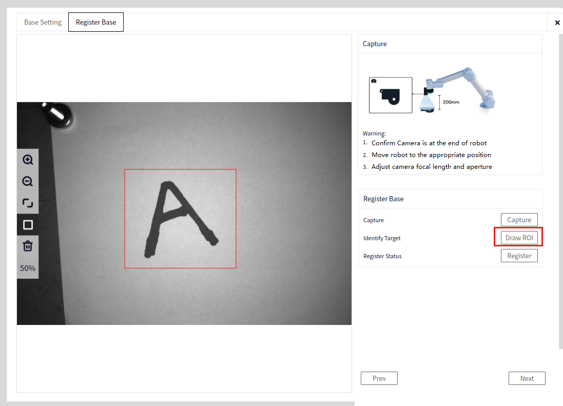
Target Recognition: Draw an area. After clicking, the ROI drawing tool will appear on the left. You can choose the ROI drawing method and frame the part to be detected using the ROI.
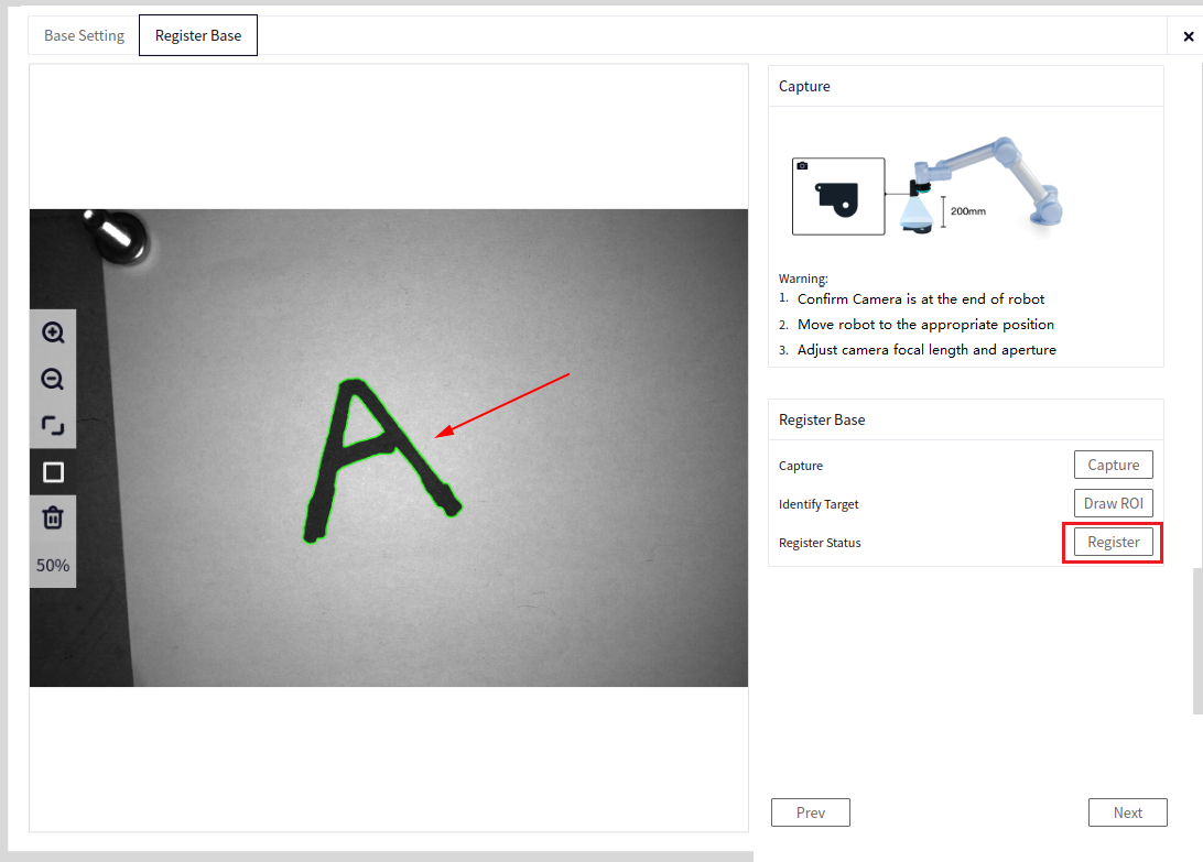
Registration Status: Click Register to record the information of the current reference position. If the registration status shows success, you can proceed with the next configuration. Otherwise, adjust the camera parameters until the image is clear.
After clicking Register, if registration is successful, the interface will display a successful registration status. The image will show the template feature points recognized within the ROI area. You can check the template feature points drawn on the image. If the feature points are evenly distributed on the target object, the features are considered good.
If registration is not successful, check whether the captured image is clear. If it is not clear, adjust the camera parameters to improve the clarity, redraw the ROI, and try registering again.
Auto Calibration#
Teaching the Photo Pose#
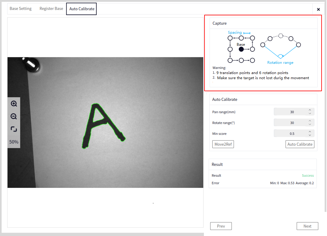
Before performing auto calibration, check the robot’s movement space to ensure there are no obstacles.
Tip
Set the translation distance and rotation range reasonably during auto calibration to ensure the camera can capture the entire target object within this range.
If the robot’s pose changes during auto calibration, return to the pose used during reference registration to ensure the robot’s pose matches the one used during initial calibration.
Auto Calibration#
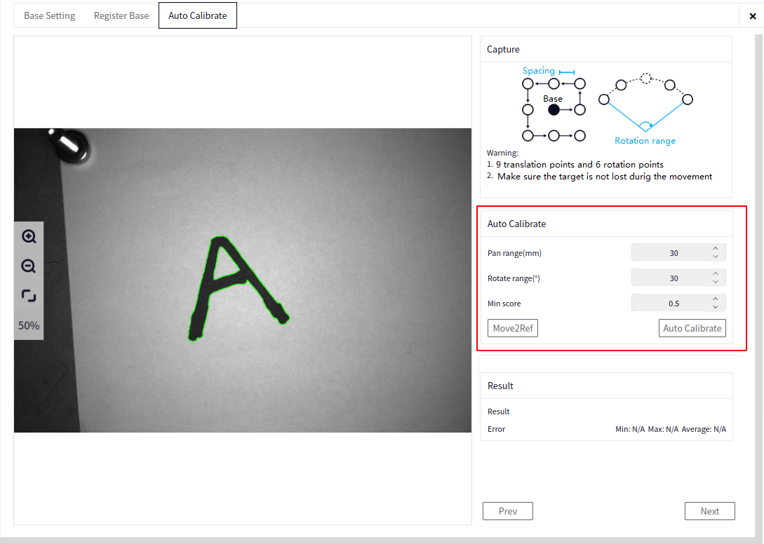
Translation Range (mm): During auto calibration, this is the translation distance between the previous calibration pose and the next calibration pose. You can decide this based on the camera’s field of view and the robot’s available movement distance.
Rotation Range (°): The range of rotation during calibration. Calibration will be performed within this rotation range.
Minimum Score: The minimum score for matching. If the score is too high, the system may not be able to recognize the target in the current pose.
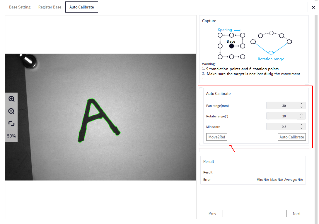
Hold to Return to Reference Position: If the robot’s initial calibration pose does not match the pose during reference registration, hold the button to return to the robot’s pose during reference registration.
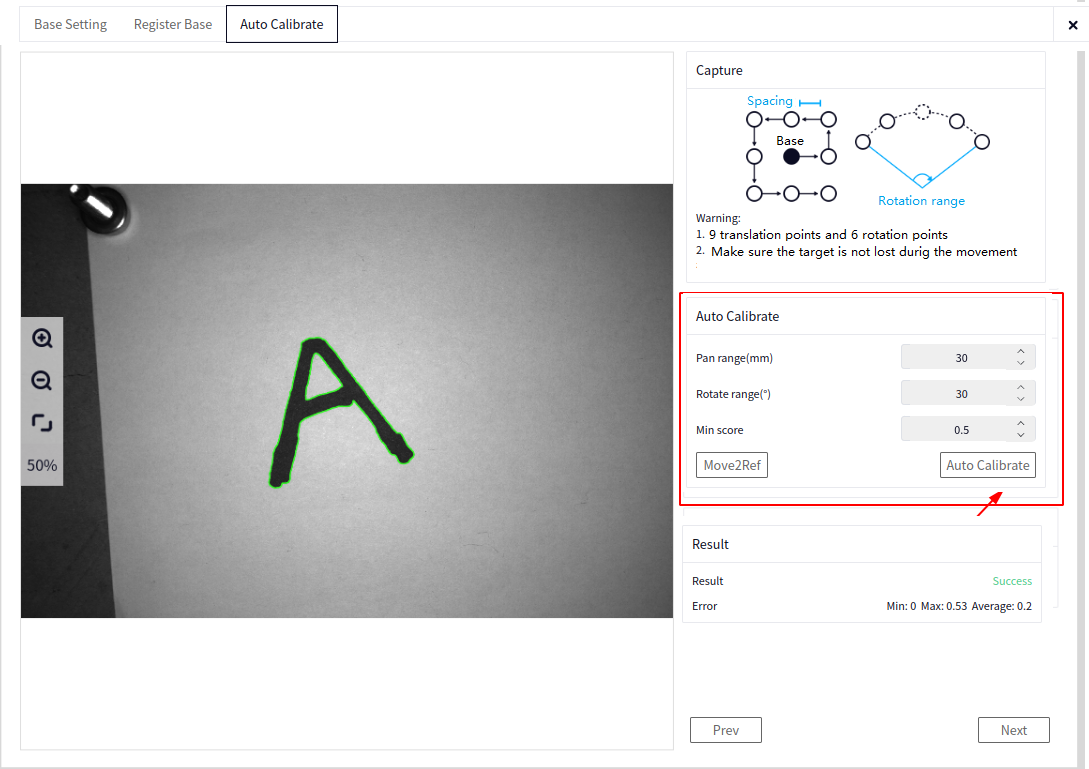
Auto Calibration: Automatically perform calibration. First, perform 9 translations, followed by 7 rotations to complete the calibration. If the target object cannot be recognized at any point, calibration will immediately stop, indicating a calibration failure.
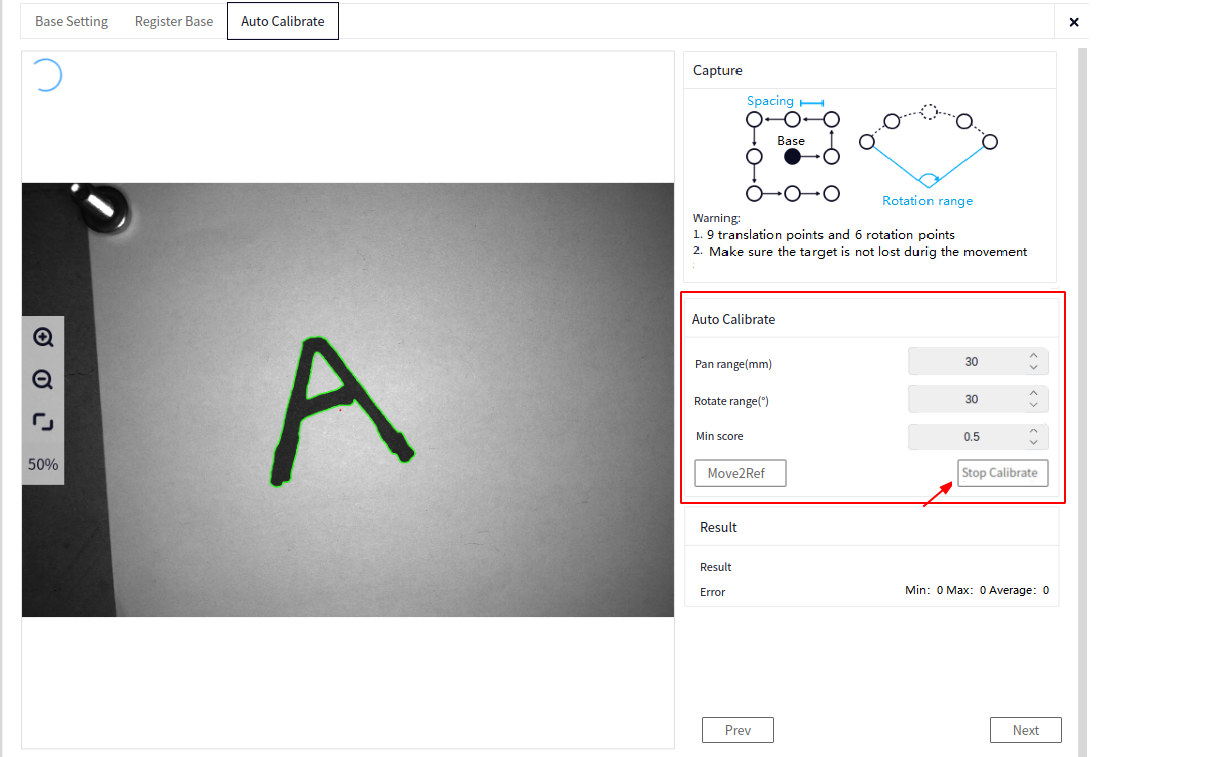
Stop Calibration: Click to stop auto calibration. To recalibrate, click auto calibration again.
Calibration Results#
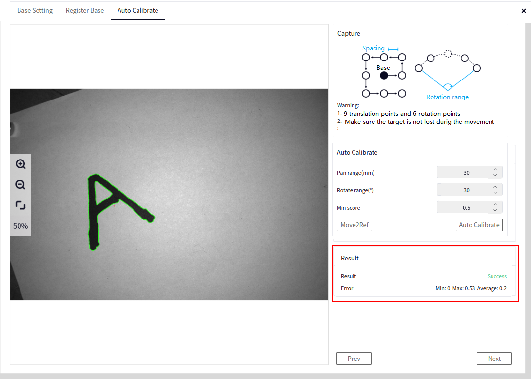
Calibration Results: If calibration is successful, the status will show calibration success. Otherwise, it will show calibration failure.
Calibration Error: If calibration is successful, the average calibration error, maximum calibration error, and minimum calibration error will be displayed.
Position Correction#
Recognition Configuration#
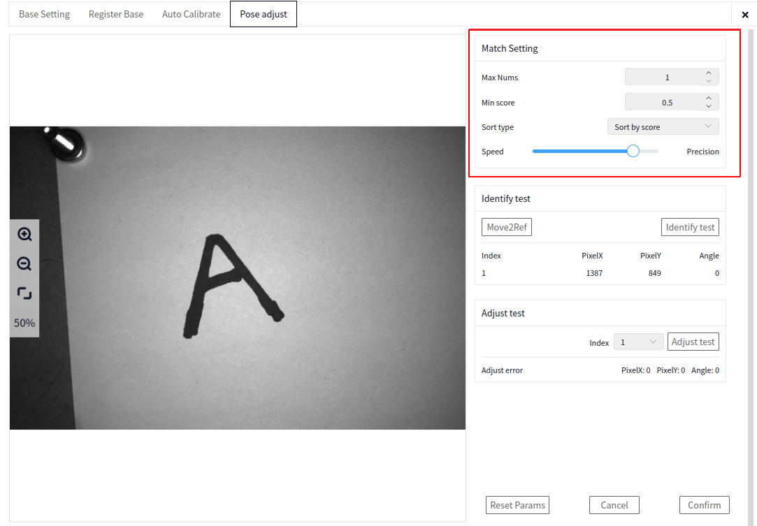
Maximum Number of Targets: Enter the maximum number of recognized targets. If there is only one target, the maximum number of targets is 1.
Minimum Score: The minimum score for recognition matching. Recognition results with a score higher than the set value will be output.
Sorting Method: The recognition results can be sorted and output in various ways, such as from highest to lowest score, left to right, right to left, top to bottom, or bottom to top. Choose a method that facilitates grabbing and sorting the recognized results.
Speed-Accuracy: Controls the recognition speed and accuracy. Moving the slider towards speed increases recognition speed but reduces accuracy. Moving the slider towards accuracy improves precision but slows down recognition.
Recognition Test#
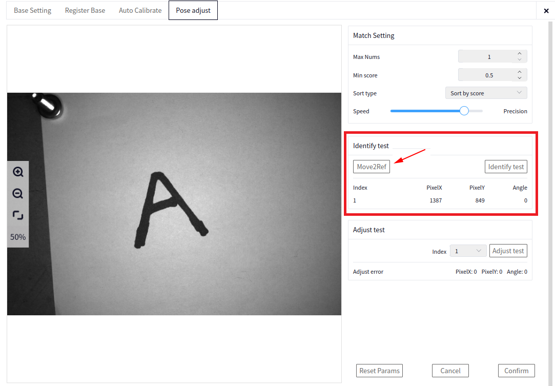
If the marker board has moved or a new marker board is used, you need to reset the marker board reference. If the marker board has not changed, this step can be ignored.
Hold to Return to Reference Position: Return the robot to the pose during reference registration.
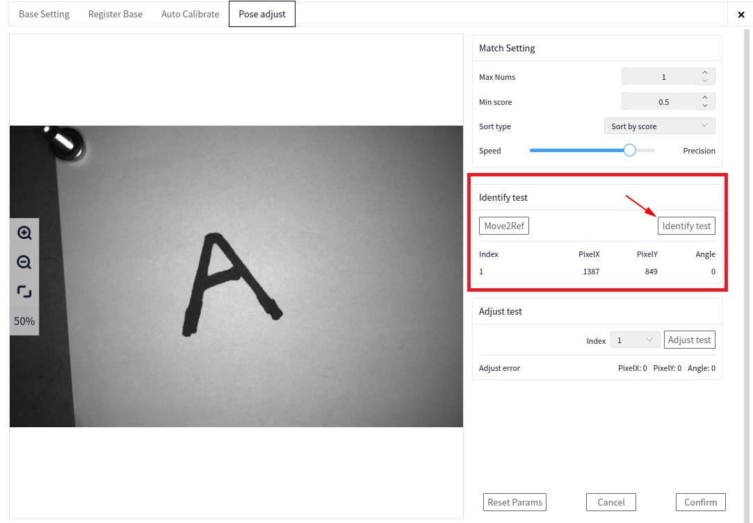
Recognition Test: After completing the recognition configuration, perform a recognition test. The recognized results will be displayed on the image on the left. If the results are unsatisfactory, adjust the recognition configuration parameters and perform the recognition test again.
Correction Test#
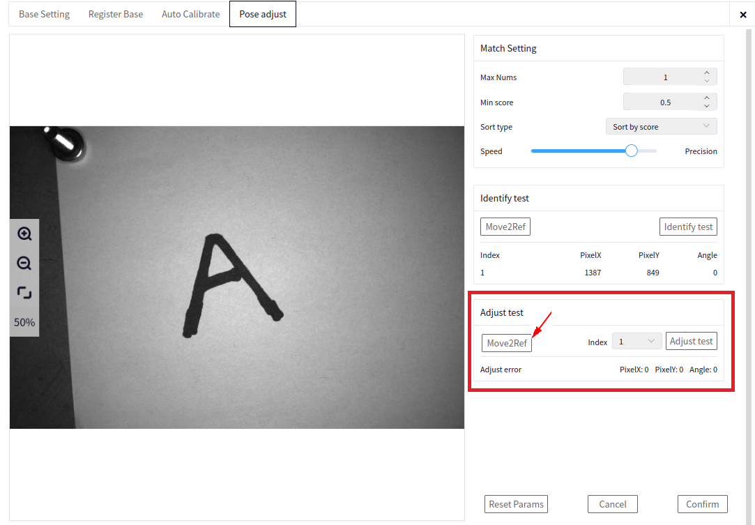
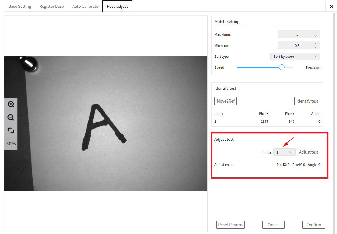
Hold to Return to Reference Position: Return the robot to the pose during reference registration.
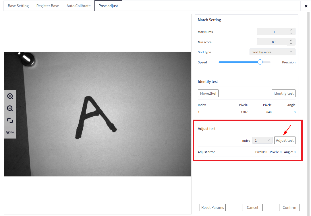
Index: Select the correction index. There will be one correction for each recognition result.
Correction Test: Select a correction index to perform correction. The robot will move to the relative position between the robot and the target object during reference registration.
Reset All Parameters#
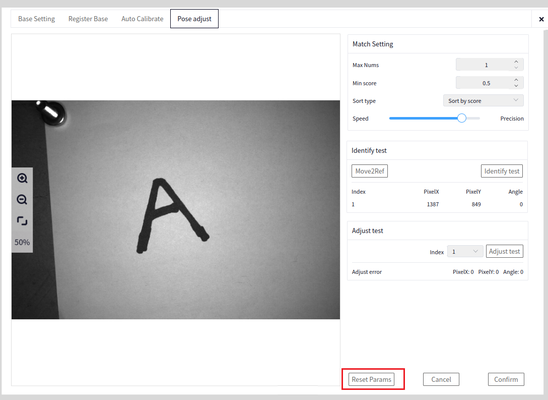
Reset all parameter configurations in the Basic Settings->Position Correction interface and reconfigure the intelligent block process.
Cancel#
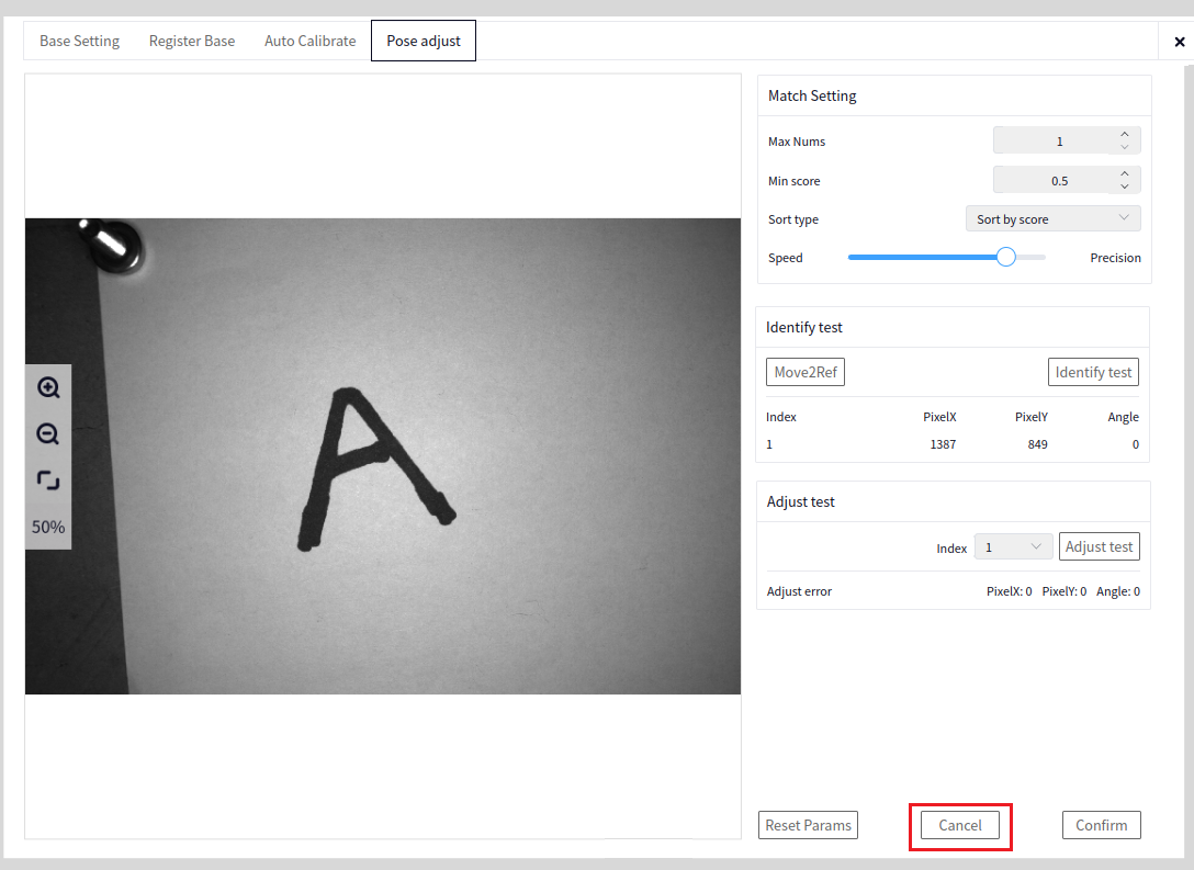
Cancel all parameter settings in the Position Correction interface. The position correction settings will revert to the default values saved in the project.
Confirm#
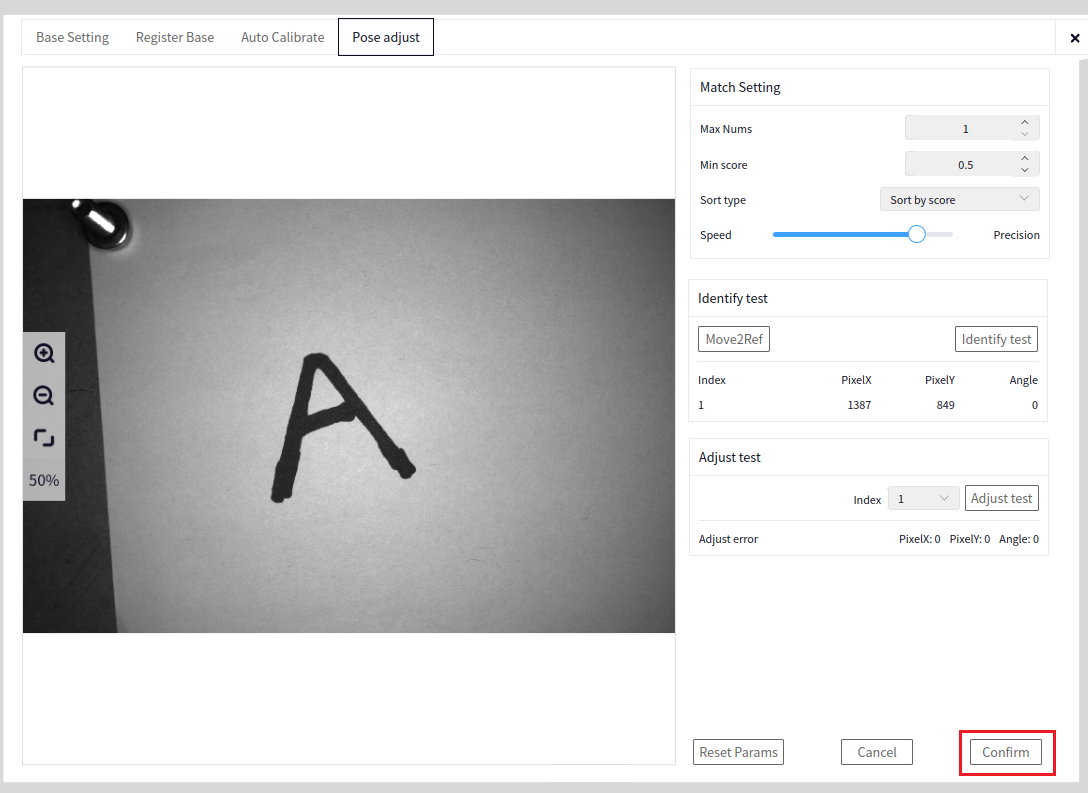
Save all parameter configurations in the Basic Settings->Position Correction interface for use in the robot-side configuration.
DUCO Core Side#
Vision Plugin#
Open the DUCO CORE interface, and click the area indicated by the arrow below to pop up the vision plugin interface. Enter the controller’s IP address and click connect.
Process#
In DUCOCORE, first connect to DUCOMind. Enter the IP of the connected MIND locally, as shown below.
Then drag out the Detection2D plugin.
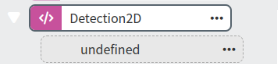
Configure the parameters in Detection2D.
Server Status#
If the server connection status is disconnected, you need to go into the DUCOMind plugin and reconnect to DUCOMind. After reconnecting, proceed with the following configurations. If the connection is successful, click the button below to go to the currently configured DUCOMind project.
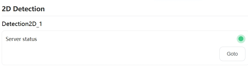
Process Configuration#
Select the 2D positioning intelligent block configured in the open project on the DUCOMind side. If no intelligent block is available, you can refresh the list.

Photo Point Configuration#
There are two options for photo points: Move to Reference Registration Point / Based on Current Position. The default option is to move to the reference registration point.
Move to Reference Registration Point: The reference registration point is a fixed robot pose, meaning the robot’s photo position is fixed.
Based on Current Position: The robot’s photo position is not fixed, and it moves to a user-defined robot pose.
Mode#
There are two correction modes: Correction and Correction with Operation. The default is Correction only.
Correction: Only performs correction on the recognized object. Other operations can be defined and added in undefined blocks.
Correction Test: Based on the current photo position, click recognize. If recognition is successful, a success message will be displayed; otherwise, it will show recognition failure. If recognition is successful, you can perform correction by holding the button (after clicking, it enters the robot movement interface, and holding the button moves the robot). The robot will move to complete the correction (in multi-target scenarios, only one correction is performed).
Teach Operation Point: Click to enter the robot movement interface (set the taught point as the grabbing point for the object). Teach the robot to move to the grabbing point.
Record Current Point: Record the operation point for grabbing the object.
Move to This Point: Move to the recorded grabbing operation point.
Offset Height of Transition Point (mm): Set the point above the grabbing operation point for the object. The default is 50mm.
Variable IO#
Recognition Success: Returns a global boolean variable, indicating whether the target object was successfully detected.
Total Number of Targets: Returns the total number of detected targets, i.e., the number of shape-matched targets.
Confirm#
Click Confirm to complete the block name record, finish the process configuration, photo point configuration, and operation point configuration, and save the configuration. This will generate the process block program.
Cancel#
Click Cancel to reset the process configuration, photo point configuration, and operation point configuration to the default state.
3D Target Positioning Application#
Create a New Project#
Open the DUCOMIND webpage. If the controller’s IP address is known, you can open the DUCOMIND webpage on another laptop or computer, provided that the device’s network is set to the same subnet as the controller’s IP. For example, if the controller’s IP is 192.168.3.10, you can access 192.168.3.10:7300.
For details, refer to Software Operation Guide->Project Management->Create New Project
After opening the DUCOMIND webpage, if a project has already been created, you can directly click the project name, and then the Open option will appear. Click Open to open the corresponding project. The image below shows the result after clicking the first project.
If you want to create a new project, just click Create New Project, as shown below:
After clicking Create New Project, the following interface will pop up, and you can enter the corresponding information.
Camera#
For details, refer to Software Operation Guide->Camera Management->Create New Camera and Software Operation Guide->Camera Management->Camera Configuration->Zhiwei Camera
Hardware Introduction#
Vision Tooling Introduction#
Vision Optional Package List#
Calibration Board Installation Diagram (Calibration board in hand)#
3D Camera Installation Diagram (Camera in hand)#
Camera Network Cable Connection#
Insert the camera network cable into the controller’s network port. Ensure that the inserted network port is set to local link only. The method to set a controller’s network port to local link only is as follows:
Method 1
Open a terminal. If using the teach pendant display, press Ctrl+Alt+F2/F3/F4 to open a terminal;
The current controller has 3 network ports, named enp1s0, enp2s0, and enp3s0;
3. For example, to set the enp1s0 network port to local link only, the command is:
sudo ifconfig interface_name 169.254.7.12 broadcast 169.254.255.255 netmask 255.255.0.0
Tip
The middle network port is generally enp3s0, the one near the HDMI interface is enp2s0, and the other port is enp1s0. The factory IPs are pre-configured, so just connect the camera network cable to the enp1s0 port.
Method 2
Open the management software (DucoManager) interface, and click Network Configuration;
After clicking network configuration, you will see 3 network statuses: LAN1, LAN2, and LAN3. These three network ports correspond to the LAN1, LAN2, and LAN3 ports on the controller;
Select LAN2 or LAN3, click settings, and set the network port to local link only.
Insert the camera network cable into the network port configured as local link only.
Camera Power Cable Connection#
The camera power supply must meet the specifications of 24V voltage and 2A current. The image below shows the standard camera power adapter information.
Caution
After the camera power is connected for the first time, the camera lens will light up and display the logo. The logo will disappear after about 10-20 seconds. If the camera lens does not light up and display the logo, or if the logo remains displayed without disappearing after being powered on, check the power connection.
Create a New Camera#
Open the newly created project or an existing project, and create a new Zhiwei Camera.
As shown in the image below, click the arrow to bring up the Create New Camera interface, and select Zhiwei Camera as the camera model.
After selecting the camera model, click the scan button indicated by the arrow below to scan for the connected Zhiwei Camera.
Tip
The result in the image above shows that a Zhiwei Camera is already connected to the local device. After clicking scan, wait a few seconds for the result.
After scanning the Zhiwei Camera, click the + sign next to the scanned camera information to create a new camera, as shown below:
After creating the camera, the name of the first camera will default to Camera 1. Click Camera 1 to bring up the camera configuration interface, as shown below:
Connect the Camera#
After clicking the Connect button, the system will attempt to connect to the Zhiwei Camera. Usually, it takes a few seconds to connect successfully. Once connected, the Connect button will change to Disconnect.
Tip
The Zhiwei Camera is a POE interface camera. After connecting to the device, you need to set the connected network port to local link only to connect successfully (if the camera IP is known in advance, setting the network to the same subnet as the camera also works).
If the camera fails to connect, an error window will pop up. In this case, check the network port configuration, and ensure the network cable and camera are in good condition. Insufficient power supply may also be the cause.
Parameter Configuration#
The image below shows the parameter configuration interface for the Zhiwei Camera.
The camera exposure parameters need to be adjusted based on the site conditions. Generally, the exposure parameter is set between 2000-3000, as shown below:
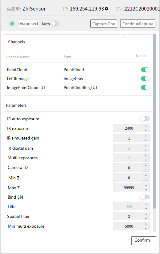
Tip
The parameters we often configure are IR Exposure and Multiple Exposures.
IR Exposure: If the camera image is too bright or too dark, adjust this parameter.
Multiple Exposures: The number of times the camera flashes (default is once, but can be set to 3).
After configuring, click the confirm button for the changes to take effect.
Robot#
For details, refer to Software Operation Guide->Robot Management->Create New Robot
Create a New Robot#
Click the arrow below to bring up the new robot interface.
Tip
The robot models supported are ducocore_gcr10 and ducocore_gcr5.
Click the Create button to create a new robot.
Connect the Robot#
Click the newly created robot name to bring up the robot configuration interface. Enter the robot’s IP and click the Connect button to connect to the robot. Once connected successfully, the Connect button will change to Disconnect, and the dot in front of the connection will turn from red to green, as shown below:
3D Target Positioning#
Select Resources->Smart Process, click the plus sign in the upper left corner of the smart process, and add the 3D target positioning smart block.
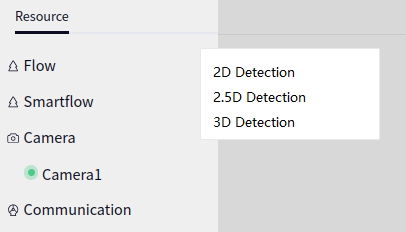
Basic Settings#
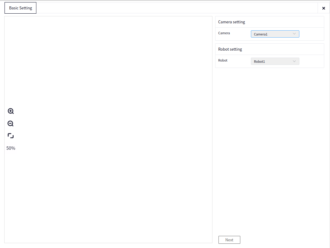
Camera Configuration: Click Camera, and select the connected 3D camera. Only 3D cameras are supported here.
Robot Configuration: Select Connected Robot, then proceed to the next step.
Automatic Calibration#
Pose Teaching for Photo Taking#
Before automatic calibration, check the following points:
Tip
Ensure the camera is installed in the eye-in-hand configuration, with the camera vertically capturing the recognition object.
Adjust the robotic arm so that the object to be recognized is in the center of the image.
Automatic Calibration#
Calibration Board Type: Select the correct calibration board for calibration. The default is DM-DB300405A.
Calibration Distance: Click measure to calculate the distance between the calibration board and the camera, then proceed with the calibration.
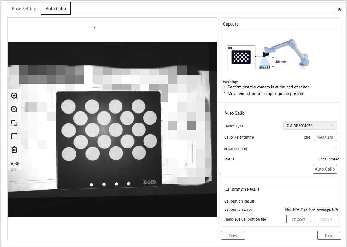
Advanced Parameters: When selected, you can modify the space height, top edge length, and bottom edge length. If not selected, the parameters will use default values.
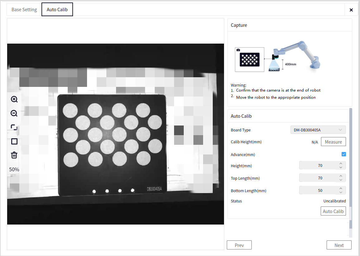
3D Hand-Eye Calibration File Import: If automatic calibration cannot be performed with the current tooling, manual calibration can be done using calibration tools, and the calibration file can be imported. After importing the calibration file, the calibration status will be marked as calibrated.
3D Hand-Eye Calibration File Export: The calibration result from the current smart process can be exported. The export file name is user-defined, and the export file path is under the resource directory of the current project.
Automatic Calibration: Click to perform automatic calibration. The window will automatically update the recognition result image.
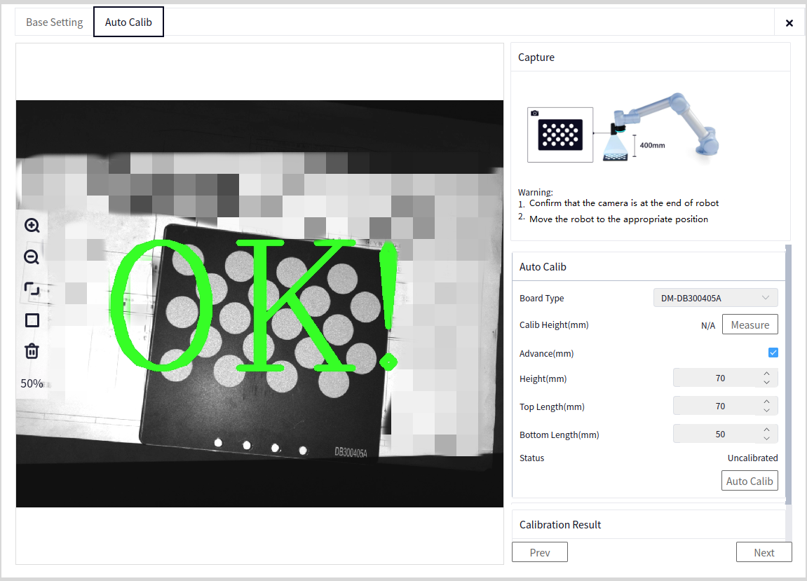
Stop Calibration: If you need to urgently pause calibration during automatic calibration, click stop calibration. To recalibrate, return to the initial calibration position and restart the automatic calibration.
Calibration Status: Indicates whether automatic calibration is successful. If successful, the status will show calibrated, otherwise, it will show calibration failed.
Calibration Results#
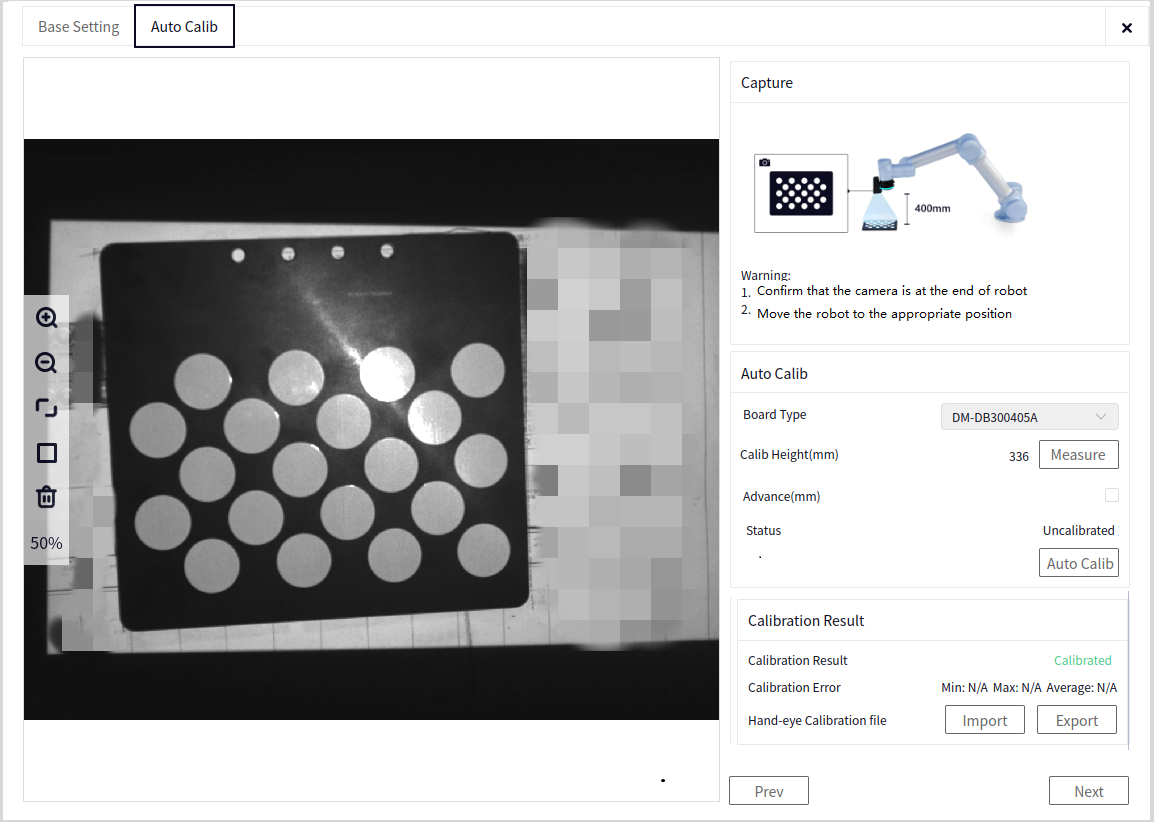
Calibration Results: If calibration is successful, the status will show calibration success, otherwise, it will show calibration failure.
Calibration Error: If calibration is successful, the average calibration error, maximum calibration error, and minimum calibration error will be displayed.
Template Segmentation#
Pose Teaching for Photo Taking#
Before pose teaching for photo taking, check the following points:
Tip
Ensure the camera is in the eye-in-hand configuration.
Move the robot end to a suitable position, making sure the marker block is in the center of the image. It is recommended that the shooting distance does not deviate more than 25mm above or below the calibration distance.
Template Data Segmentation#
Camera Photo: The camera takes a picture to get the current image.
Segmentation Method: Used to segment the marker block point cloud. Both automatic and manual segmentation are supported.
Automatic Segmentation Score: Used for automatic segmentation. If the score is too high, automatic segmentation may yield no result. The segmentation result and score will be displayed on the image.
Automatic Segmentation Precision: The higher the segmentation precision, the better the completeness of the segmented calibration block.
Automatic Segmentation: Click segmente Auto, and the segmentation result will be displayed on the left image.
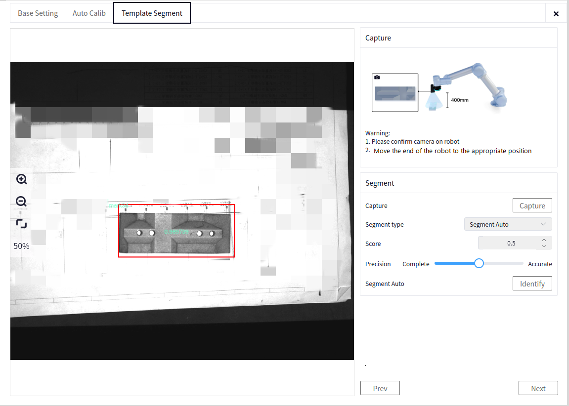
Manual Segmentation: After clicking draw region, you can draw a rotation box on the left image to enclose the marker block. Click confirm to complete the segmentation.
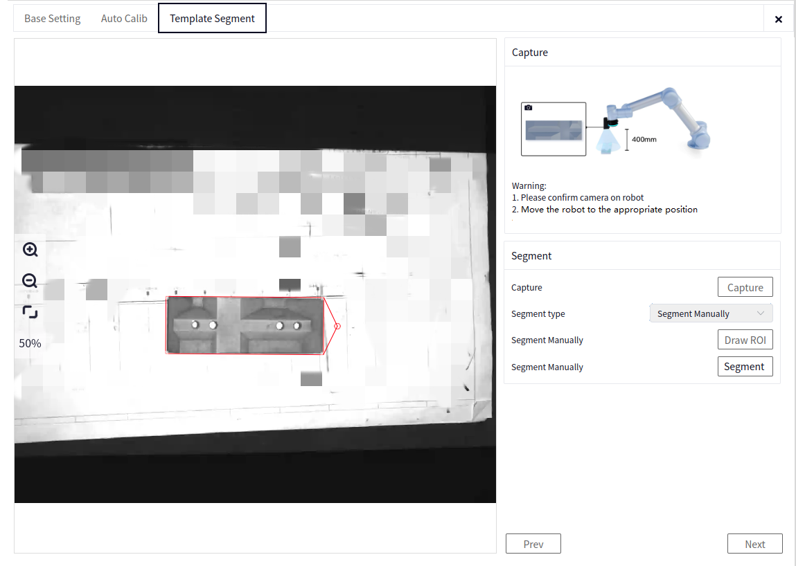
Model Refinement#
Refinement Tools#
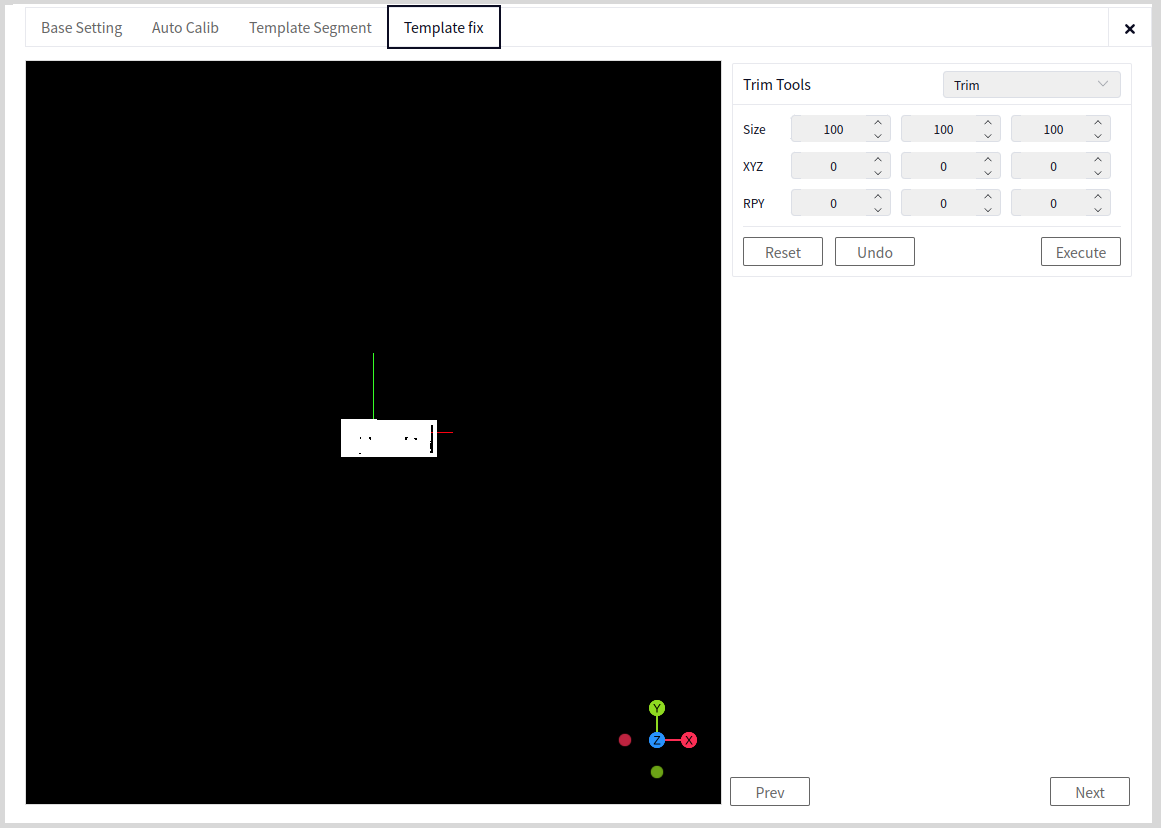
Refinement Tools: Various tools are provided here to refine the template point cloud. Select and modify as needed.
Reset: Resets all refinement operations, restoring the point cloud to the segmented point cloud.
Undo: Undoes the current refinement operation on the point cloud.
Execute and View: Executes and views the current refinement operation on the point cloud.
Tip
The refinement tools are synchronized with the template creation tools. Refer to the template creation tools for usage.
The recommended refinement sequence is: Auto Center Reset -> Erase Point Cloud -> Filtering.
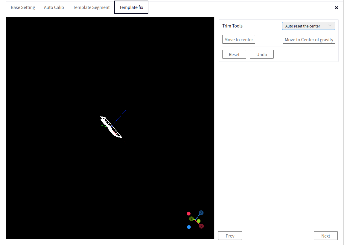
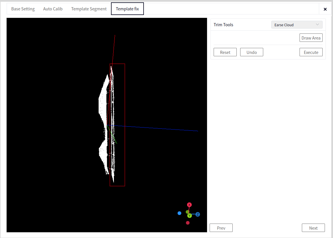
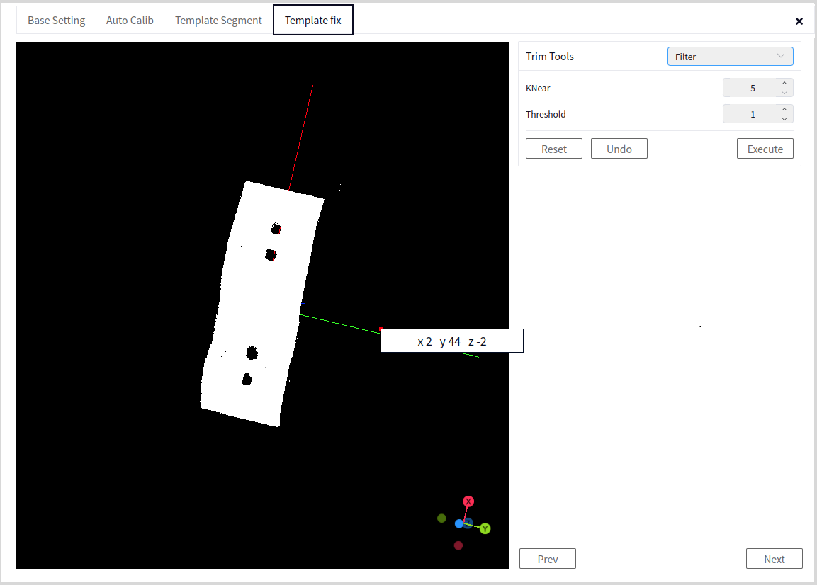
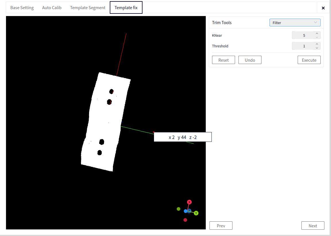
Template Generation#
Viewpoint Redirection#
XYZ: Defines the viewpoint direction of the normal vector. Generally, set the Z value to -100.
Feature Calculation#
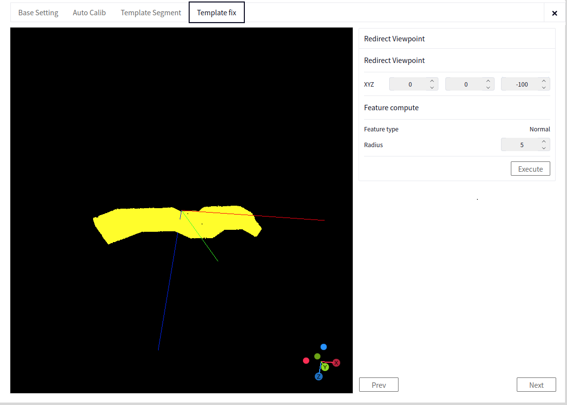
Feature Type: Normal. The default is normal and cannot be modified.
Radius: Feature calculation radius, default is 5mm.
Execute and View: Obtain the normal point cloud.
Recognition Configuration#
Recognition Configuration#
Automatic Segmentation Score: Used for automatic segmentation. If the score is too high, automatic segmentation may yield no result. The segmentation result and score will be displayed on the image.
Automatic Segmentation Precision: The higher the segmentation precision, the better the completeness of the segmented calibration block.
Minimum Overlap Rate: The minimum overlap rate between the point cloud matching result and the template. If the overlap rate is too high, there may be no pose output.
Advanced Parameters: Coarse matching point cloud sampling value, generally set to the default value. Coarse matching pose usage rate, generally set to the default value.
Recognition Test: Perform the photo-taking, segmentation, and matching operations in sequence to obtain the matching result.
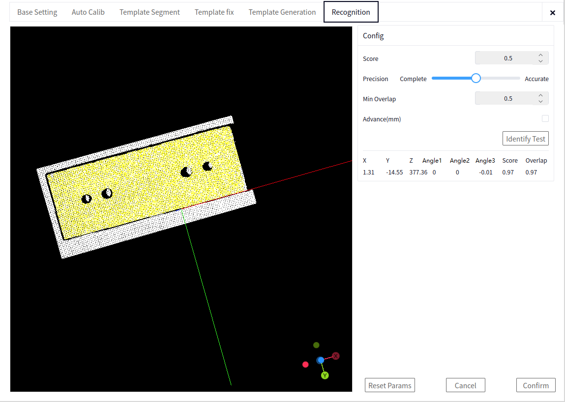
Reset All Parameters#
Resets all parameter configurations in the Basic Settings->Recognition Configuration interface, allowing you to reconfigure the smart block process.
Cancel#
Cancels all parameter settings in the Recognition Configuration interface, and restores the positioning correction to the default values saved in the project.
Confirm#
Saves all parameter configurations in the Basic Settings->Recognition Configuration interface for use in robot configuration.
DUCO Core Side#
Vision Plugin#
Open the DUCO CORE interface, click the area indicated by the arrow in the image below to bring up the vision plugin interface. Enter the controller’s IP address and click connect.
Process#
In DUCO CORE, add the process as shown in the image below.
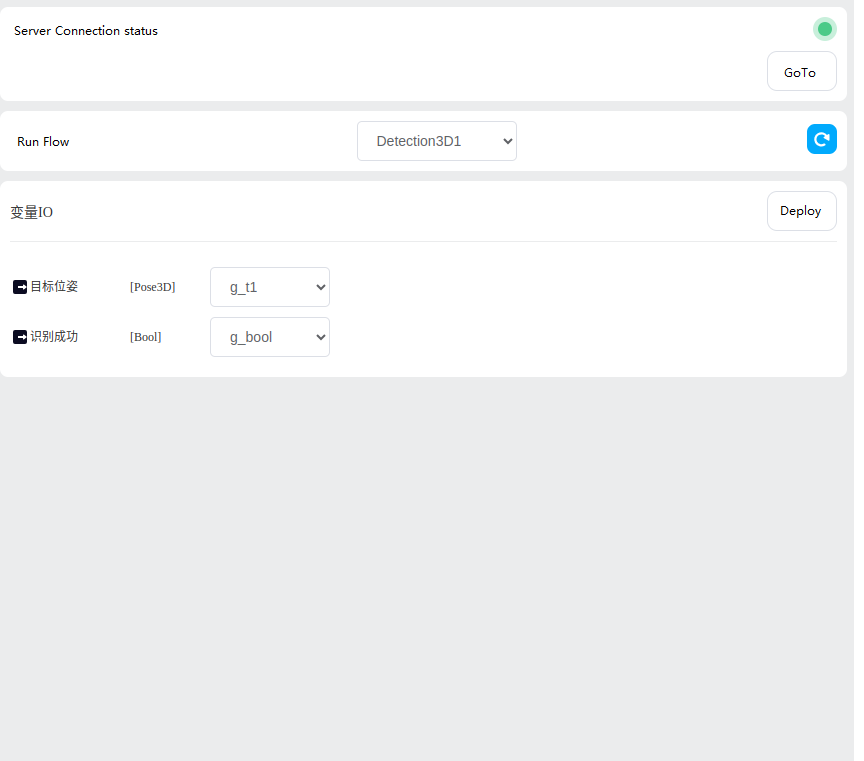
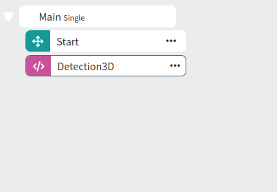
Create a pose-type variable g_pose and a bool-type variable g_check. In the Detection3D process, select the process created in the previous step, and choose g_pose and g_check as the variables.
Here, g_pose represents the pose of the marker block in the robot’s base coordinate system, and g_check indicates whether the marker block was recognized in the current photo. If the marker block is recognized, proceed with the grasping operation.
For the grasping operation, please refer to the 3D Marker Board Positioning Application DUCO Core section.