Inicialized Basic Configuration#
Language Configuration#
When initializing the configuration, click on “English” in the upper right corner to change the language mode, as in
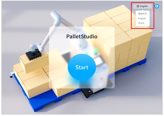
Figure 5.22 Language Switching Configuration
Workstation Configuration#
Start Point Configuration#
1 First of all, you should set the Start Point of the robot, click “Teach” to enter the teaching pop-up window, as in Figure 5 .23
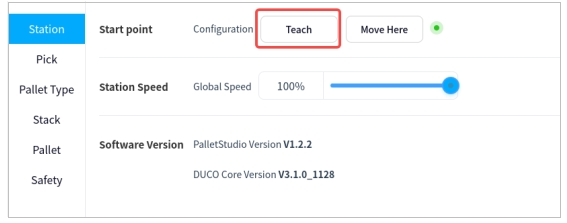
Figure 5.23 Start Point Configuration
In the pop-up window, perform manual teaching, of which the first column is the joint point movement, the second column is the end six degrees of freedom point movement, and the third column is the elevation axis point movement. Click “Record” after the teaching is finished, as in 2
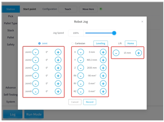
Figure 5.24 Start Point Teaching Pop-Up Window
Tips:
By clicking “Leveling”, the attitude parameters RX and RY of the robot end can be adjusted to the level of the end;
Press and hold on “Home” to lower the elevator shaft position until it returns to zero, release to stop immediately;
Click “Record” to make this position adjustment effective;
The subsequent demonstration process can be referred to here, and will not be explained later.
3 Click “Move Here” to move the end of the robot to the initial position just taught, as in Figure 5 .25
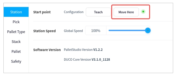
Figure 5.25 Initial Position Configuration
Tips:
Pressing and holding “Move Here” will cause the robot to continue moving, releasing it will abort it, and pressing and holding will not work once it reaches the preset point, so please be aware of the risk of collision and interference during the movement process, which will not be repeated hereafter.
Station Speed Configuration#
The global running speed of the station is adjusted by means of a slider, as shown in
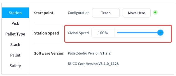
Figure 5.26 Schematic Diagram Of Workstation Speed
Software Version#
The current PalletStudio software version and DUCO Core version requirements are displayed here, as shown in Figure 5 .27
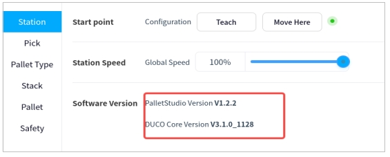
Figure 5.27 Schematic Diagram Of Software Versions
Pickup Configuration#
The pickup position demonstration involves a pick wait point, a pick lift point, a pick point, and a pick lift height, with the point relationships shown in Figure 5 .28. Among them, the pick lift point is used to set a transition point above the pick point that can avoid the interference of the baffle plate on the box.
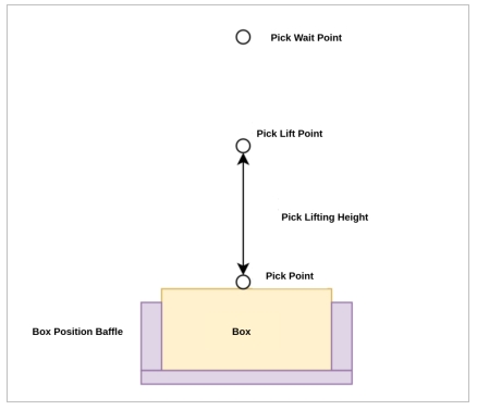
Figure 5.28 Plot of Pick Wait Point, Pick Lift Point Vs. Pick Point
Pick Wait Point Configuration#
The pick wait point is generally located above the pick lift point, this point is used to wait for the box in place signal to be triggered.
Select “Pick Wait Point” → “Teach” to enter the teaching pop-up window for adjusting the waiting point for picking up materials at the end of the robot. Teach in the pop-up window (refer to the previous section for the teaching process).As shown in Figure 5 .29
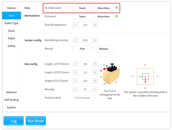
Figure 5.29 Configuration Interface of Pick Wait Points
Pick Point Configuration#
The pick point is the point at which the end of the robot sucks up the box.
Select “Pick Point” → “Teach” to enter the teaching pop-up window for adjusting the pickup point at the end of the robot. Teach in the pop-up window, as shown in Figure 5 .30

Figure 5.30 Configuration Interface of The Pick Point
Tips:
When teaching the pick point, please note that the position of the suction cups should be placed so that the distance from the suction cups to the upper and lower (left and right) edges of the box are approximately the same, such as Figure 5 .31

Figure 5.31 Schematic Diagram of Suction Cup Position
Pick lift Height Configuration#
The purpose of setting the pick lift height is to avoid the interference of the baffle plate during the pickup process at the end of the robot by adjusting the pick lift height.
Click directly on the number to activate the keypad for input, or select “+” and “-” to adjust the lifting height (in millimeters) of the robot end to pick up the material. As shown in Figure 5 .32:
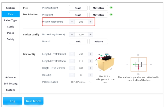
Figure 5.32 Configuration of the Pick Lift Height
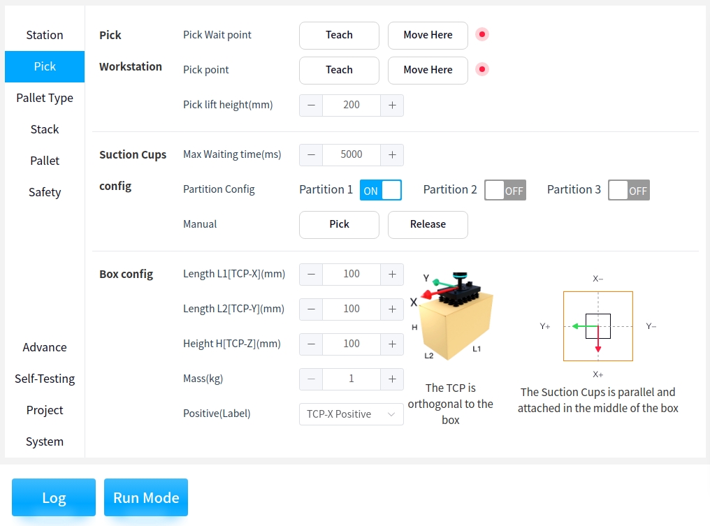
Suction cup Parameter Configuration#
The Maximum Vacuum Wait Time (ms) is the maximum amount of time that the robot end needs the suction cups to generate enough vacuum while sucking up the box. If sufficient vacuum is not generated within the specified time, a fault is reported.
The max waiting time can be determined according to the actual situation, and the suction cups can be operated manually by clicking on “Pick” or “Release”.As shown in Figure 5 .33
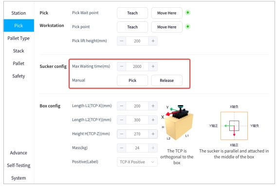
Figure 5.33 Suction Cup Configuration
If you have selected a multi-partition suction cup, you can select the partition that is enabled. If you choose to enable partition 1 and partition 2, partition 1 and partition 2 of the suction cup will be opened during reclaim.
Box Parameter Configuration#
The box parameters (in millimeters) and the box mass (in kilograms) are adjusted according to the actual situation, where the length L1, length L2, and height H of the box are along the X-, Y-, and Z-axes of the TCP coordinates, respectively.
The box front face (labeling direction) is related to the later stack configuration. If accurate control of the box orientation (pattern side or label side) is required, correctly select the box front orientation (based on the positive and negative directions of the X and Y axes of the end TCP coordinate system) and ensure consistent orthogonality of the box orientation.
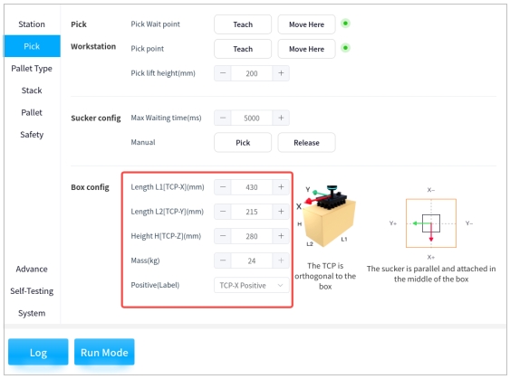
Figure 5.34 Box Configuration
Tips:
The suction cup tool coordinate system is orthogonal to the box, as shown in Figure 5 .35
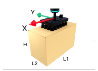
Figure 5.35 Coordinate System of Suction Cup Assembly
As shown in Figure 5 .36, please select the front orientation of the box correctly according to the following TCP coordinate system
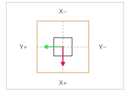
Figure 5.36 Selection of the TCP Coordinate System for the Box Front Orientation
Pallet Type#
Click on “Pallet Type” → “Open” to access the configuration pop-up window for stacks and layers, as shown in the following figure.
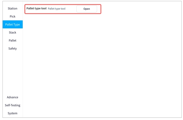
Figure 5.37 Pallet Type Tool
Pallet Type Base Configuration#
As shown in the figure below, it is possible to manually switch the configuration scheme of Pallet types and layers directly
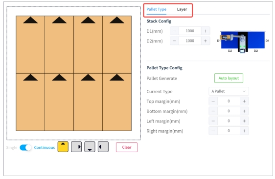
Figure 5.38 Schematic Diagram of Pallet Type and Layer Configuration Scheme
The parameters of the pallet can be adjusted according to the actual situation (in millimeters), where D1 and D2 are the side lengths of the pallet, as shown in the following figure.
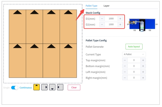
Figure 5.39 Configuration of Stack
Note: The diagram below shows the side lengths of the stack
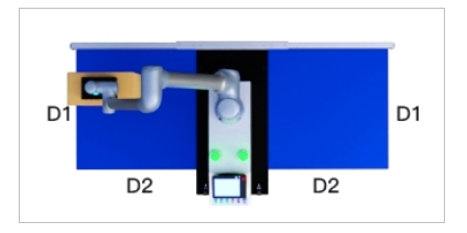
Figure 5.40 Schematic Diagram of the Side Lengths of the Pallet
Pallet Generate can choose “Auto layout”, which is explained in
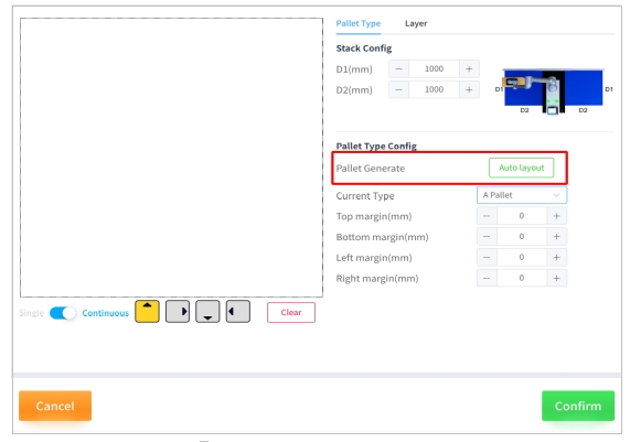
Figure 5.41 Auto Layout Configuration
The stack configuration allows you to select between stack A and stack B by using the drop-down boxes and to plan the stacks according to the icons at the bottom left, as shown in the following figure
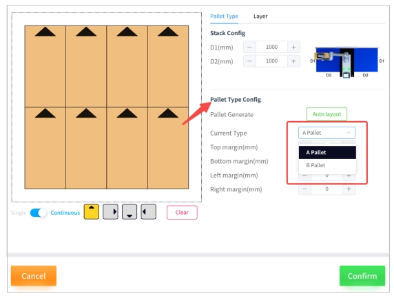
Figure 5.42 Pallet Type Configuration
Among the icons at the bottom of the left side, “Single/Continuous” determines whether or not the boxes are placed continuously on the layer, the four gray icons with arrows represent the four different box types with different frontal orientations, and “Clear” empty all the boxes placed on the layer. As shown in the figure below
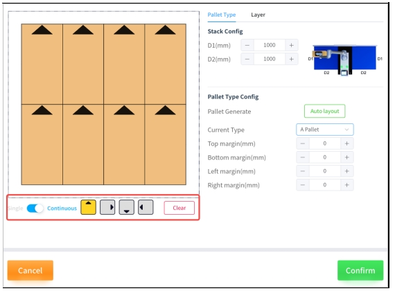
Figure 5.43 Bottom Icon
The upper, lower, left and right margins in the stack configuration are the reference boundary distances (in millimeters) between the box and the outer edge of the stack plate, with positive values being boundary inward expansion and negative values being boundary outward expansion. In the lower Figure 5 .44 the palletized plate configuration is shown as a solid line and the margin reference line is shown as a dashed line
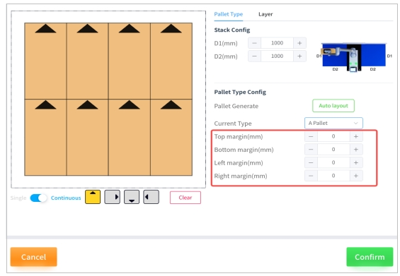
Figure 5.44 Configuration of the Stack Margins
In the layer configuration, it is possible to adjust the tolerance between layers, the number of layers, and the type of stack selected for each layer, as shown in Figure 5 .45. When the configuration is complete, click “Confirm”.
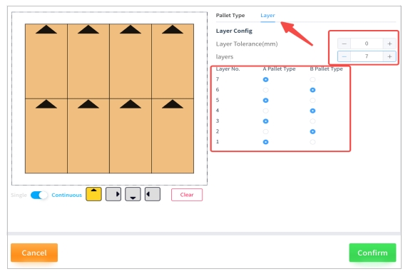
Figure 5.45 Layer Configuration
Tips:
The “Layer Tolerance” is a certain height reserved for the box when the robot end is placed on the box, a positive value is the clearance, a negative value will be pressed, please fine-tune according to the actual situation. Below is the diagram for a positive layer tolerance.
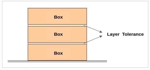
Figure 5.46 Layer Tolerance
Automatic Layout Configuration#
After clicking on “Auto layout”, you can select the type of stack, the alignment mode, the orientation of the front side and the maximum stack height according to the actual situation, as shown in Figure 5 .47
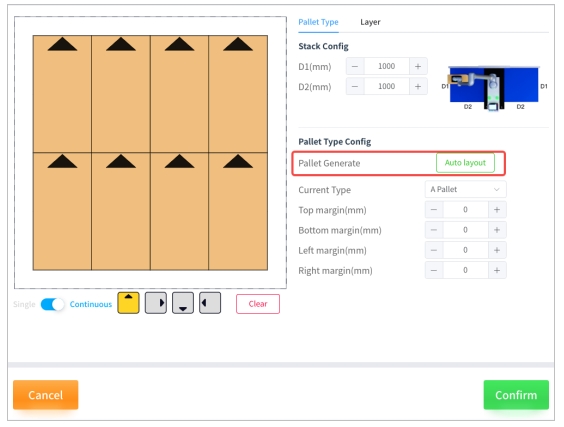
Figure 5.47 Auto Generate Layout
Among the types of stacks,
Cheessboard: The boxes are all placed horizontally or vertically;
Rotary-pattern: Place the box in a swingback fashion in circles;
Crosswise-pattern: Arrange the boxes in columns, vertically and horizontally.
In alignment mode,
Center: the boxes are gathered together and centered;
Stretch: The boxes are spread out with a certain distance between them.
In the frontal direction.
Uniform: the front orientation of the box labels are placed consistently, by column;
Outward: In circles, the front direction of the box label is placed outward.
In the maximum stack height setting,
Automatic: the accessibility check is carried out from the highest height, knowing that all boxes are accessible;
Customize: Start from the given height downwards to find the maximum height that meets the conditions.
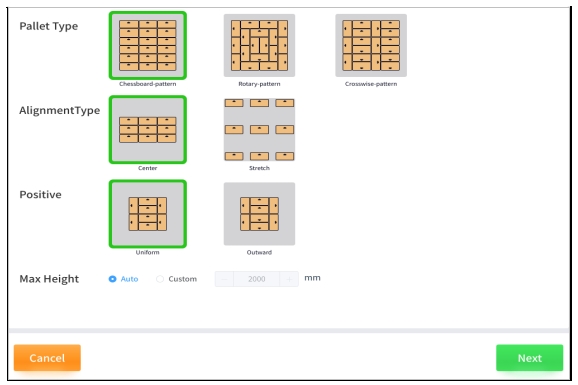
Figure 5.48 Auto Layout Configuration Diagram
Tips:
Automatic Layout uses the stack type selected for the base configuration as the configuration template, and stack B is a 90-degree clockwise alignment of stack A;
The outer contours of stacks A and B are aligned.
Clicking on “Next” displays the result of the automatic Layout and shows below the number of layers to be selected, the maximum possible stack height and the number of boxes per stack.
In the generated result, the
Number of layers: the number of reachable layers calculated automatically based on automatic or customized heights;
Pallet height: the corresponding stack height is automatically updated when the number of layers is modified;
Boxes per pallet: automatically update the corresponding number of boxes when modifying the number of layers.
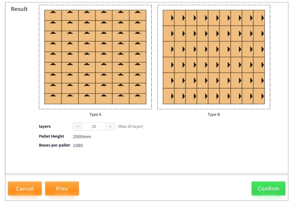
Figure 5.49 Generated Results of Automatic Layout
Stack configuration#
Click on “Stack” and select “ON/OFF” to determine if the pallet configuration is enabled or disabled. If it is not enabled, the pallet will not place any boxes when palletizing. As shown in Figure 5 .50
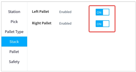
Figure 5.50 Stack Configuration
Palletizing Configuration#
In palletizing, the transition point is the point of attitude position that needs to avoid obstacles and thus be set artificially during the process from the pickup waiting point to the subsequent placing point after the end of the robot picks up the box, i.e., the trajectory flow is as follows:
Pick-up wait point → Pick-Lifting point → Waypoint 1 (optional) → Waypoint 2 (optional) → Waypoint 3 (optional) → Placet points (automatically generated)
Note: Be sure to teach the transition point in the zeroed state of the elevator.
Waypoint Teach#
1 Select “Left/Right Pallet” → “Waypoint 1/2/3” → “Teach” to enter the transition point teaching pop-up window, as shown below
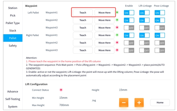
Figure 5.51 Illustrative Diagram of Waypoint
2 Select “ON/OF” to determine the Waypoint’s enable, lift linkage, and attitude linkage. Among them, “Enable” represents whether the Waypoint is activated or not, if not, it will not pass through this point; “Lift Linkage” represents whether the robot end will be lifted automatically with the elevator when it passes through this point; “Pose Linkage” represents whether the robot end will follow the placed box when it passes through this point or not. “Posture linkage” represents whether the robot end will automatically adjust its posture after passing the point based on the placed box. As shown in the following figure
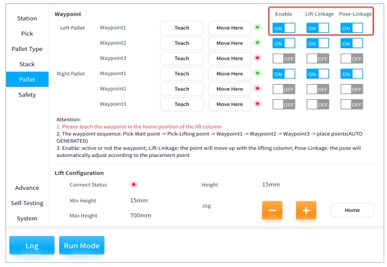
Figure 5.52 Illustrative Diagram of Waypoint
Tips:
Figure 5 .53 is a schematic diagram of the “lift linkage”. The left subfigure shows the machine at the transition point. If the lift linkage is not turned on, the end of the robot does not rise when the elevator rises (i.e., as shown in the middle subfigure), but if it is turned on, the end of the robot rises when the elevator rises (i.e., as shown in the right subfigure).
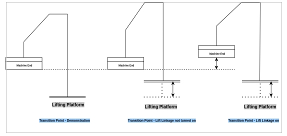
Figure 5 .54 shows the schematic diagram of “pose linkage”. The left subfigure shows the teaching state of the machine at the transition point. If the linkage is not turned on, the robot end will not automatically adjust its posture after the placement point when passing through the transition point (i.e., as shown in the middle subfigure), and if the attitude linkage is turned on, the robot end will automatically adjust its posture after the placement point when passing through the transition point (i.e., as shown in the right subfigure).
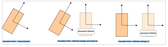
Figure 5.54 Pose Linkage
Lift Configuration#
The current connection status of the elevator, the minimum/maximum height it can reach and the current height are displayed here, and the configuration of the elevator can be changed by manual adjustment. In this case, “Home” is used to return the elevator to the zero position. As shown in Figure 5 .55
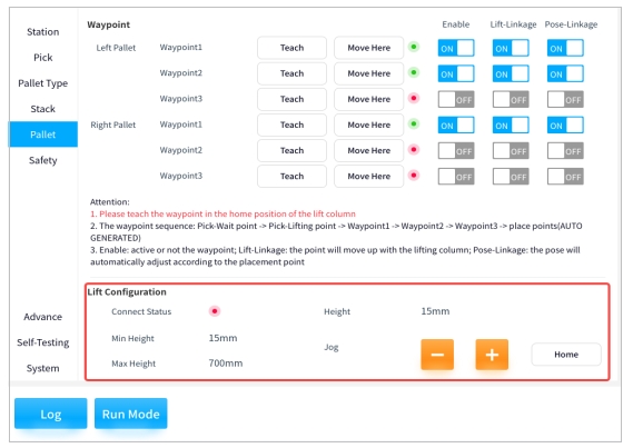
Figure 5.55 Lift Table Configuration Diagram
Safety Configuration#
Currently undeveloped features
Figure 5.56 Safety Configuration