


Transportation, installation and use#
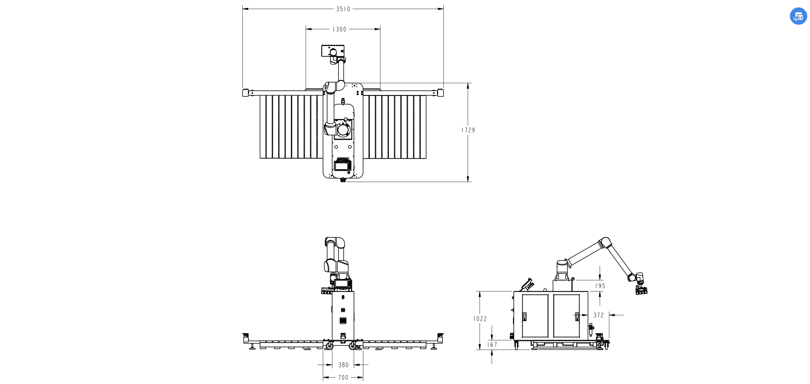
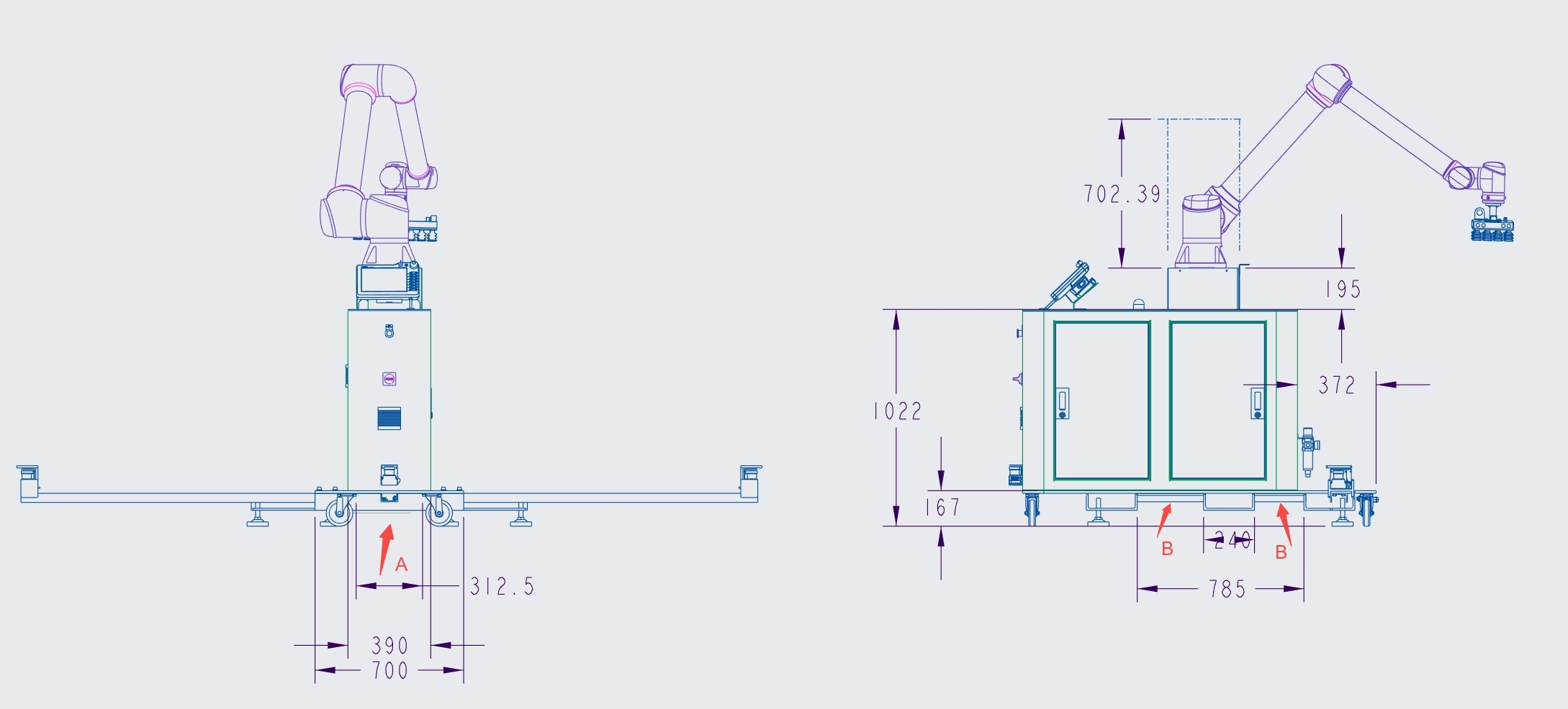
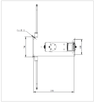
Size of the Whole Station#
Transportation of Palletizing Workstations#
The palletizing workstation is transported using a forklift truck and the base of the palletizing workstation allows it to be lifted from the left, right and rear directions. The following diagram shows the alignment of the slots and the base and the corresponding dimensions.
Tips:
If the robot is still mounted on a column or lifting post during handling, it needs to be adjusted for attitude, and after the end is turned sideways, the robot arm must be tied up with sturdy packing materials to protect it from potential damage.
Pallet Applicable Size:
Refer to the standard “GB/T 2934-2007 Intermodal Transportation Flat Pallet Main Dimensions and Tolerances”.
Deployment Requirements#
1 Extension rod assembly (take care that the foot cups are not screwed down too low in advance): the extension rod is used to prevent tipping and to assist in limiting the pallet.
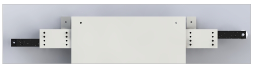
When the palletizing workstation arrives, the reach rod will be secured to the inner end. It will be necessary to remove the 8 x M8 screws and then pull out the extension rods and align the holes in the lower end separately to secure them. The final molding is shown.

2 When placing the workstation, use a flat surface as much as possible. When encountering a non-flat surface, use a wrench to adjust the leveling seat to avoid wobbling.
1 Turn the upper hexagonal nut clockwise to loosen the leveling feet.
2 Turn lower hex nut clockwise to lower leveling foot cups
3 Turn the lower hexagonal nut counterclockwise to raise the leveling feet.
4 Turn the upper hexagonal nut counterclockwise to lock the leveling foot cups.
If the palletizing workstation is not frequently relocated, it can be fixed to the floor by means of foot positioning points (adjust the foot cups upwards so that the whole base plate lands on the floor). The diagram below provides a reference for the dimensions of the fixing points:
At least 2 people should perform the robot installation at the installation site at the same time, otherwise there is a risk of damage to the machine or personal injury, never by a single person.
The robot and the control cabinet are fixed on the base plate as a finished product and should not be disassembled in principle. If necessary, please contact the technical support to operate under guidance, the robot body is heavy and requires at least 4 people to assist in carrying.
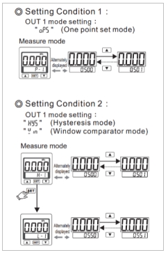
3 Air pipe connection: the front reserved air pipe is connected with the air source, diameter φ10; The on-site gas source pressure needs to be stabilized at 0.5-0.6Mpa. The threshold value of the digital pressure switch is set as follows:
4 External 220V power connection: The power cord here needs to be connected to an external 220V power source, please refer to the electrical schematic diagram for details. The switch of the control cabinet will be turned on by default, if there is a need to turn off, remove the left side panel to operate the switch.
Maintenance#
After the completion of equipment commissioning, the maintenance work shall be carried out according to the specified maintenance period.
Maintenance Term Regulations Form
Maintenance activities |
Period Maintenance |
Every 1 month |
Every 6month |
Every 12 month |
Every 36 month |
|---|---|---|---|---|---|
Clean-up operation |
|||||
Clean the control box (Replace the filters) |
X |
X |
|||
Clean the lifting column, add lubricating oil |
X |
X |
|||
Clean the robot |
X |
X |
|||
Inspection activity |
|||||
Check the robot base mounting bolts |
X |
X |
|||
Check the mounting bolts of the robot end wash plate |
X |
X |
|||
Check the robot joint mounting bolts |
X |
X |
|||
Check light strip seals |
X |
X |
|||
Check joint seams for grease spills |
X |
||||
Check the information label and nameplate |
X |
X |
|||
Check the cable harness |
X |
X |
|||
Check robot joint back cover and bolts |
X |
X |
|||
Check the emergency stop |
X |
X |
|||
Check teach pendant 3-position enable switch |
X |
X |
|||
Check control cabinet safety inputs and outputs |
X |
X |
|||
Check teach pendant cables and conectors |
X |
X |
|||
Check control cabnet fan filter |
X |
X |
|||
Check control cabnet IO terminal block |
X |
X |
|||
Check control cabnet power connector |
X |
X |
|||
Period maintenance:
It is referring to the regular implementation of the relevant maintenance. The actual interval depends on the robot’s operating period, work environment and sports mode. In general, the shorter the operating period; the more serious the work environment pollution; the more rigorous exercise mode, the shorter the interval of regular maintenance should be.
When performing a job on the maintenance list, a visual inspection must be carried out based on the following points:
Check the safety device, plug connection and printed circuit board is securely installed;
Check the label, nameplate is clear and unspoiled;
Check if the cable is damaged;
Check the connection of the ground potential equalization lead;
Check all equipment components for wear or damage.