Configure robot connection#
The configuration files generated through the “Moveit_setup_assistant Environment Configuration” step are intended for robot simulation testing only. To establish communication with a real robotic arm, the following steps can be implemented.
The current development package duco_ros2_driver includes URDF files for all arm types in the duco_support folder and provides corresponding moveit_config configuration files. The available models include:
--duco_gcr3_618_moveit_config --duco_gcr5_910_moveit_config --duco_gcr7_910_moveit_config --duco_gcr10_1300_moveit_config --duco_gcr10_2000_moveit_config --duco_gcr12_1300_moveit_config --duco_gcr14_1400_moveit_config --duco_gcr16_960_moveit_config --duco_gcr16_2000_moveit_config --duco_gcr20_1100_moveit_config --duco_gcr20_1400_moveit_config --duco_gcr25_1800_moveit_config --duco_gcr30_1100_moveit_config --double_arm_moveit_config
The development package also includes data interface and communication interface files:
--robot_control --duco_ros_driver --duco_msg
Using the GCR3-618 model robotic arm as a physical connection example:
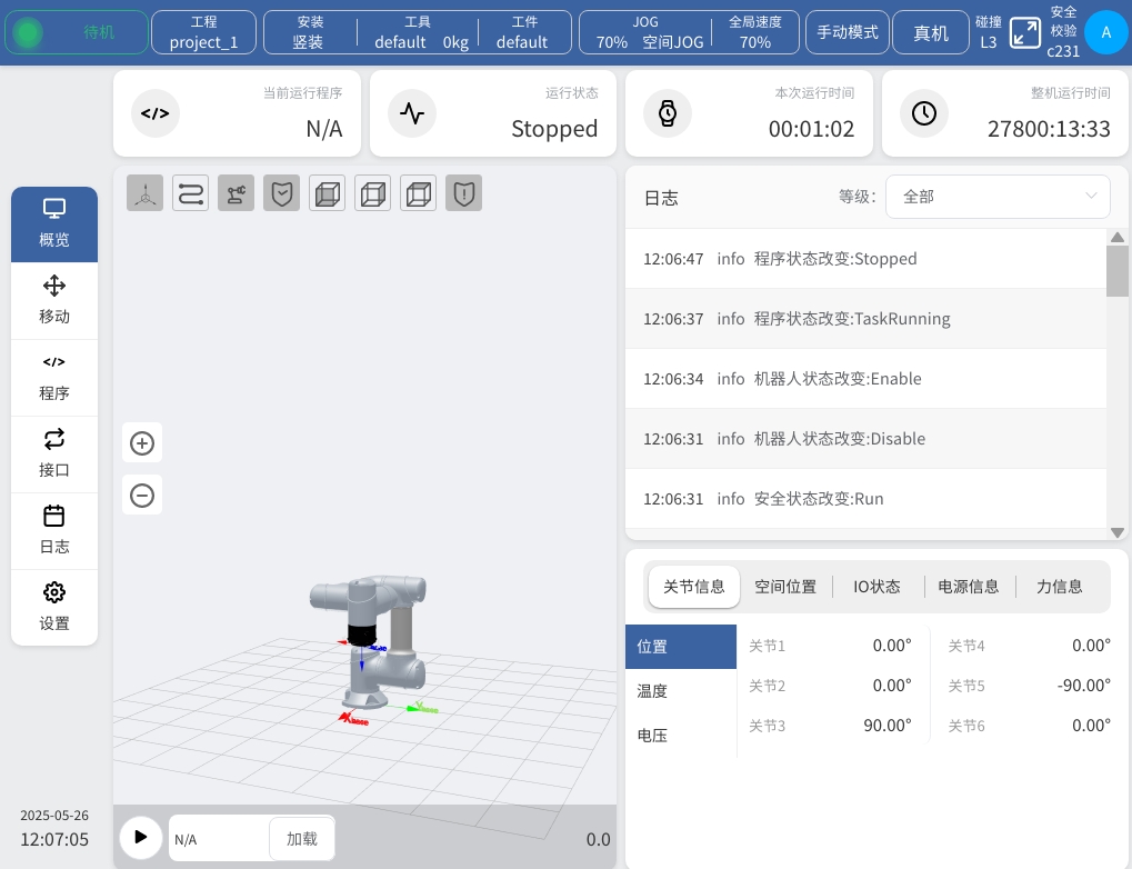
Confirm the DucoCore controller is running, and check the controller’s IP address in the “Network Settings” interface.
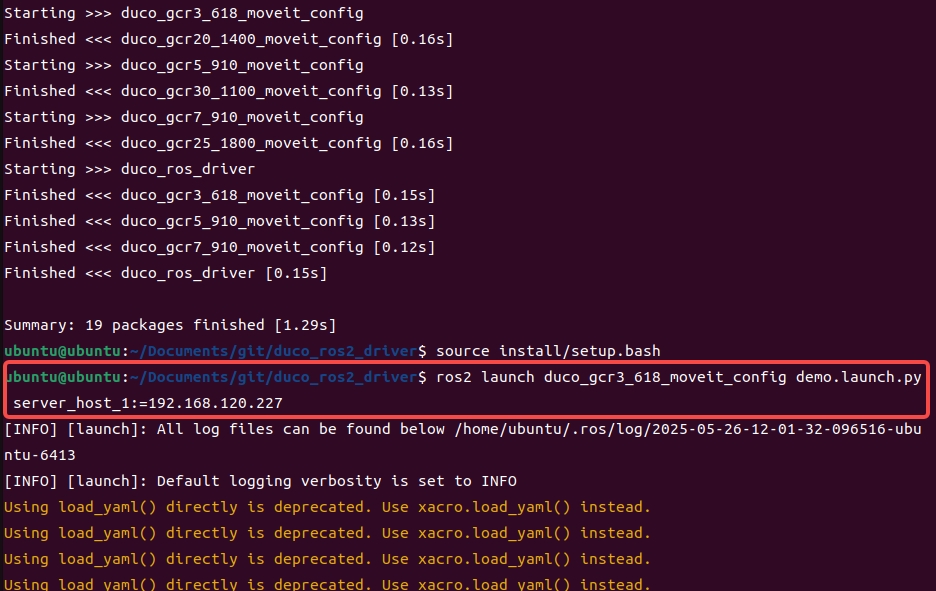
After a full compilation of packages in duco_ros2_driver, source the environment, then run the model’s demo.launch.py file with the controller IP:
1colcon build
2source install/setup.bash
3ros2 launch duco_gcr3_618_moveit_config demo.launch.py server_host_1:=<controller_ip>
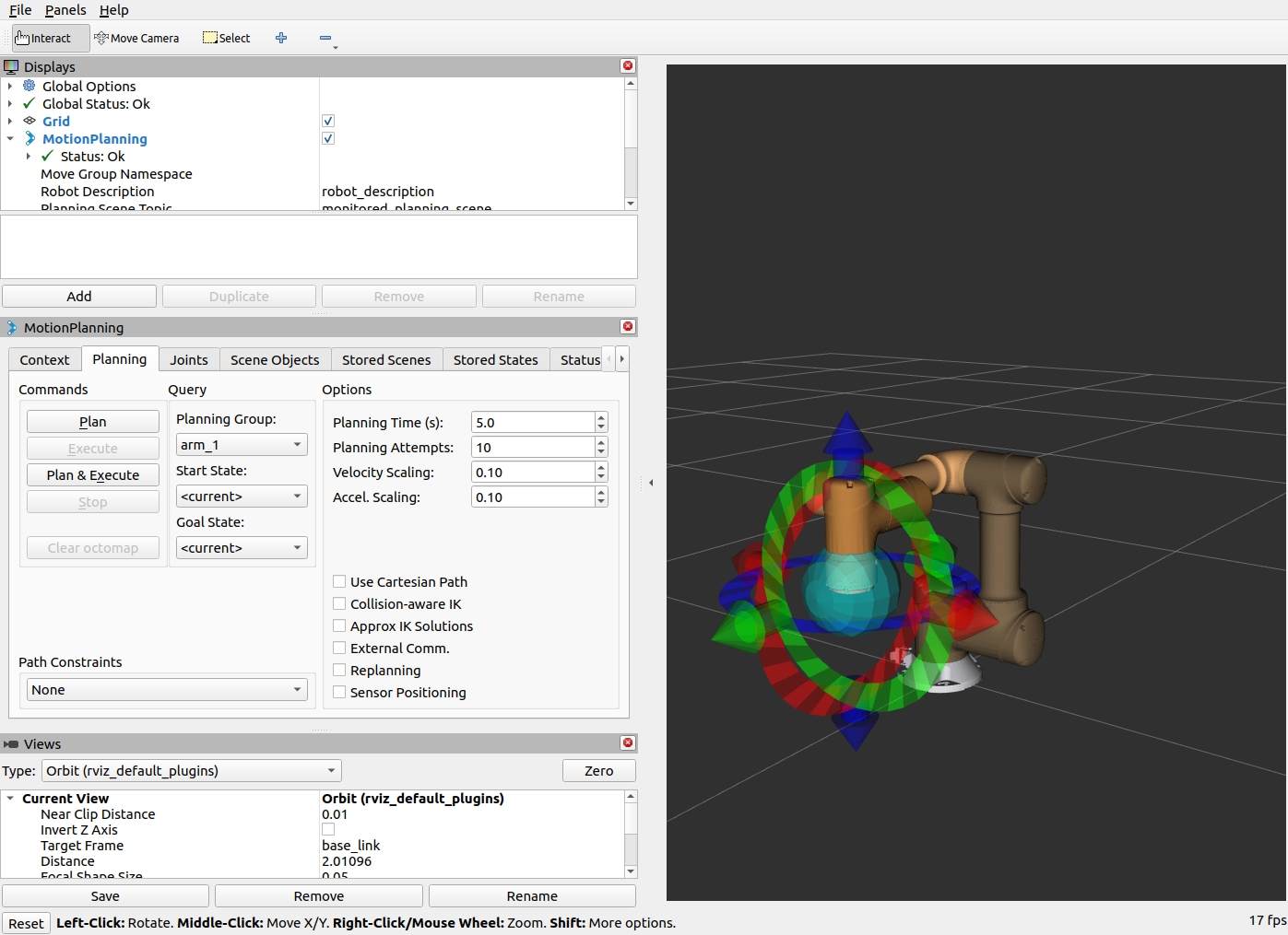
Verify the robotic arm state displayed in the opened RViz simulation interface matches the actual physical state.