Project Configuration#
Communication Settings#
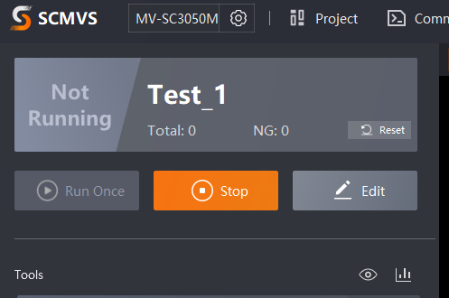
Click on Communication Settings, as shown below.

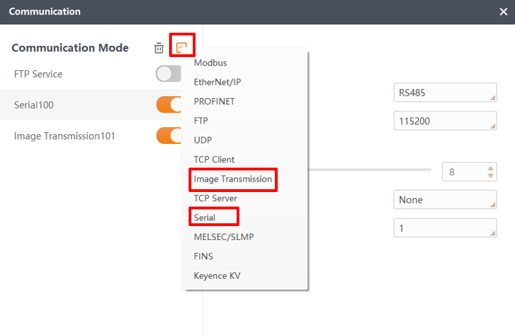
Click the plus sign in the communication list to add serial communication and image transfer.
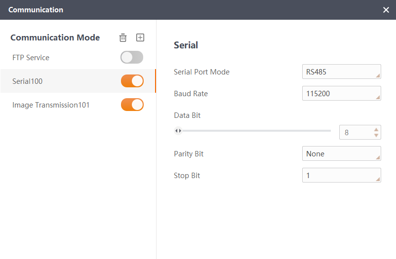
Configure the serial port communication. The following figure shows the configuration: select RS-485 as the serial port mode, set the baud rate to 115200, and the data bits to 8.
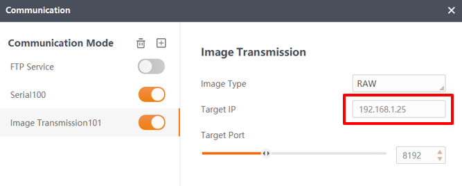
Configure the image transmission as follows: set the destination IP to the Internet Protocol version 4 IP address configured by the PC client, the image format to RAW, and the destination port to 8192.
Attention
Here, only the target IP of image transmission is variable and needs to be changed to the IP set by the PC terminal. All others just need to be configured according to the picture. If the image transmission and serial communication are not configured correctly, it will lead to the failure of automatic calibration.
Project Configuration#
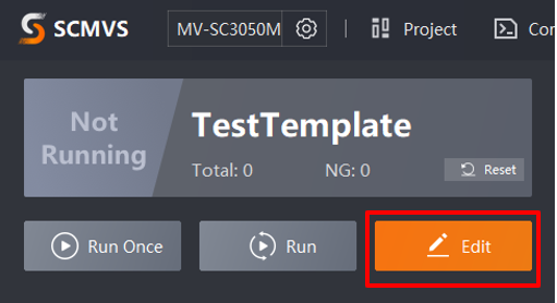
By default, there should be a default program. Click Edit to enter the program configuration screen, as shown in the figure below.
Camera Parameter Configuration#
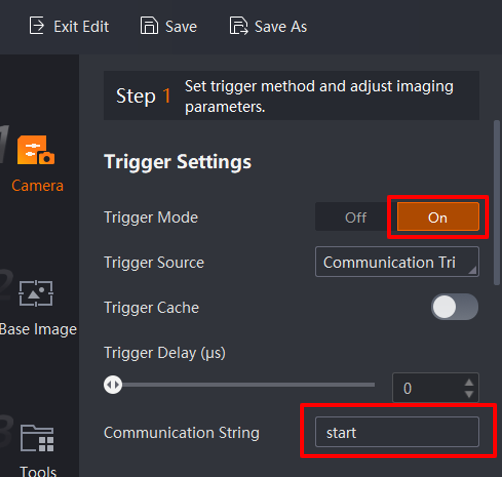
Change the trigger mode to external trigger, the trigger source to communication trigger, the trigger cache to off (default), the trigger delay to 0, and the communication string to start.
Note
The communication string can be defined by yourself, but it must be consistent with the character communication string input from the robot plug-in side; otherwise, it can’t be changed. As shown in the figure.
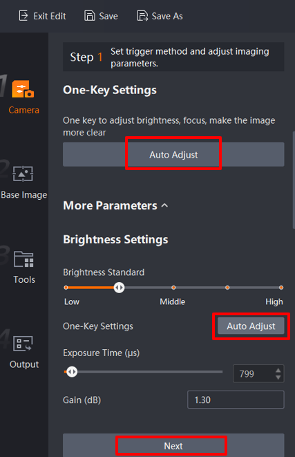
Auto Adjust:The camera focus, aperture, and other parameters can be adjusted by clicking Auto Adjustment, as illustrated in the following figure. Should further settings be required, the user manual for the software can be consulted.
Attention
The flash must be fully open; the default setting is fully open, high-frequency flash mode.
Base Image Configuration#
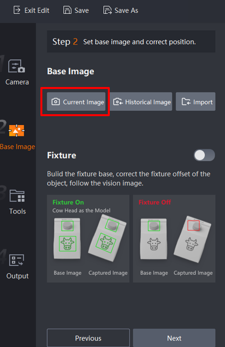
Click the Next button to enter the Base Image configuration. Select Current image and click the OK button to set the current image as the base image. Click the Next button again.

Tool Configuration#
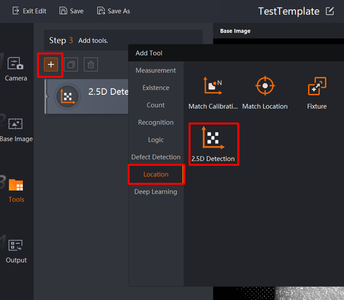
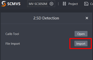
Click the plus sign, select Location, and select 2.5D Detection to load the 2.5D Configuration screen, as shown in the figure below. The user can then proceed to configure the 2.5D Detection.
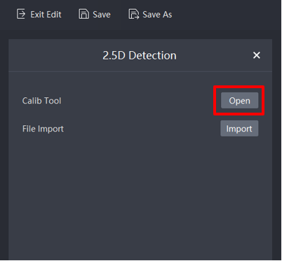
Click 2.5D Detection to access the screen below. Open the 2.5D Calibration Tool by clicking on Open. After calibrating and registering is successful, import the saved conifguration file for use in run mode
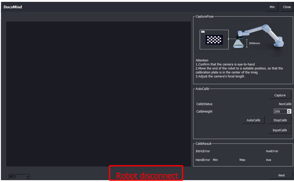
Open the calibration tool interface as shown below.
Calibrate Configuration
4.1. Firstly, establish a connection with the robot. If not, please check whether the plugin on the robot side has been installed successfully. If it has been installed, check whether the plugin mode switch is correct (the mode should be switched to configure mode). If the plugin on the robot side is confirmed to have been installed successfully and the mode has been changed to configure mode, wait for 5 seconds, and then the connection with the robot can be established.
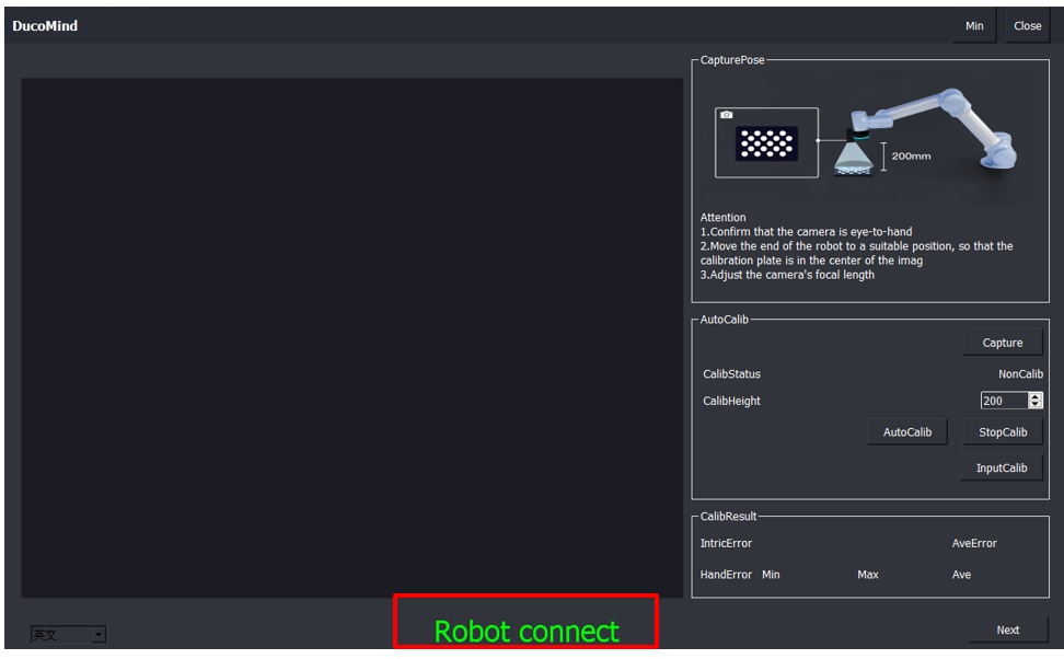
4.2. Click on Capture to adjust the position of the calibration plate under the current camera image, ensuring the plate is in the center of the image.
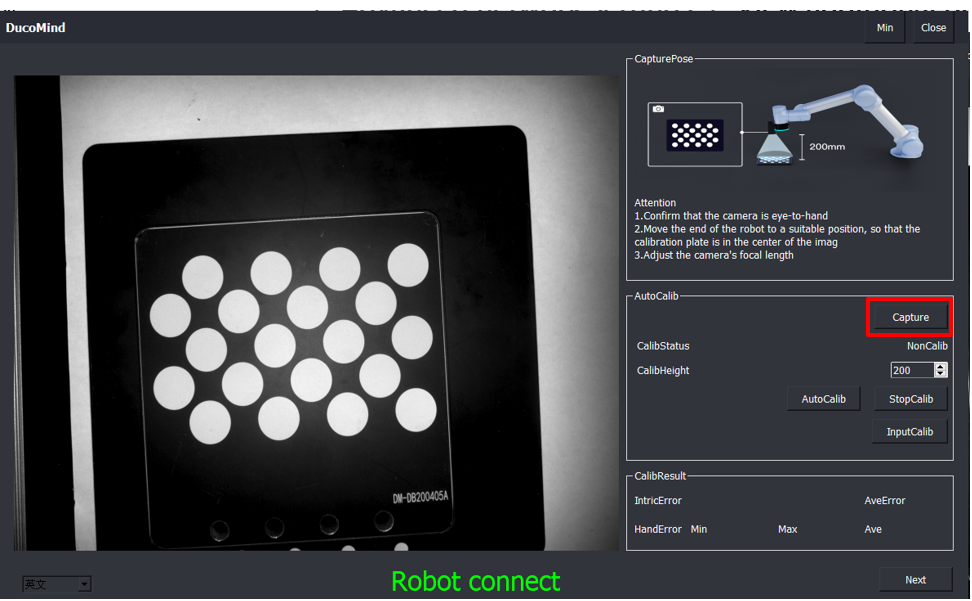
4.3. Confirm that the camera is mounted on the end of the robot arm, determine the height of the photo, and provide an approximate distance of the calibration plate from the camera.
4.4. Click AutoCalib to calibrate.

Attention
The robot moves in three levels of height, the bottom level has the smallest radius of movement (roughly radius range of 30-50mm), while the middle level has an increased radius of movement of 30%, and the top level has an increased radius of movement of 30% on top of the middle level, and during this process, attention is paid to the robot’s trajectory to prevent collisions.
4.5. Calibration Status:Which includes:Internal calibration in progress,Hand-eye calibration in progress,Calibration stopped,Calibration failed,Calibration file imported successfully.
4.6. If the robot collides during the calibration process, you can click Stop Calibration or press the Emergency Stop button. If the emergency stop button is pressed, the camera will power down, causing the SCMVS software to logout and the configuration will need to be done again.
4.7. After the calibration is finished, the calibration error can be seen at CalibResult. When using, you can mainly observe the average value of the hand-eye error. If the average value is greater than 0.5, the calibration can be re-calibrated under the requirement of high-precision positioning (e.g., 0.5mm).

4.8. Importing Calibration File: If the camera parameters are not adjusted, the same calibration file can be used. Only the registration point needs to be reset, and the configuration needs to be saved after resetting the registration point.
Register Configuration
5.1. Click Next to enter the registration screen.
5.2. Minimize: Minimizes the interface window.
5.3. Close: Closes the calibration window.
5.4. Registration status: Indicates the status of the Marker code (unrecognized, recognized successfully).
5.5. Baseline Registration:Baseline registration: Before clicking on registration, the Marker code needs to be placed in the center of the camera’s field of view.
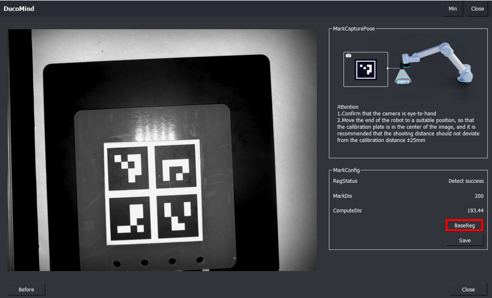
5.6. Calculated distance: The calculated distance is the actual distance between the marker and the camera. If it is too far or too close, it is only a comparison with the entered calibration plate and camera distance, giving an intuitive display of the distance.
5.7. Save configuration: Save calibration file and registration points.

5.8. Complete: Calibration completed and file saved.
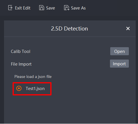
5.9. Importing Saved Configuration: Import the saved configuration file into the program and click Next.
Output configuration#
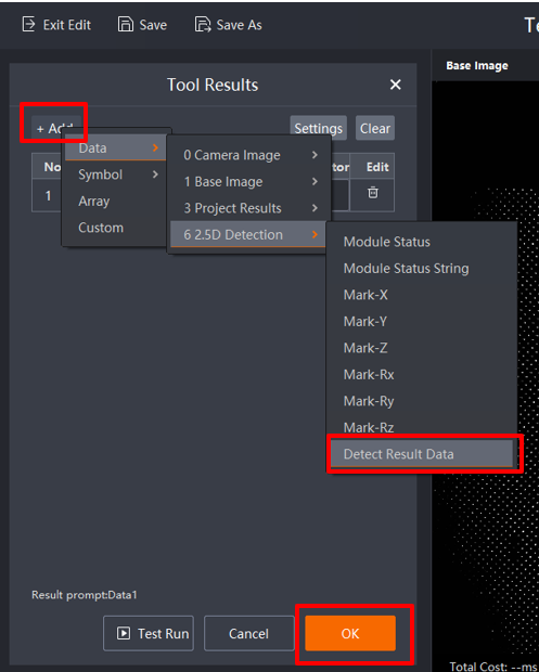
Configure the output result. Select the configuration of the completed 2.5D Detection result output, click OK, save the configuration project, and define the name of the configuration project.
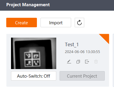
Project Switching Configuration#
When the program configuration is complete, the project name needs to be changed. Do not set the same name for different projects to prevent the machine from switching projects during the running state. When the smart block switches projects, a switch error occurs.

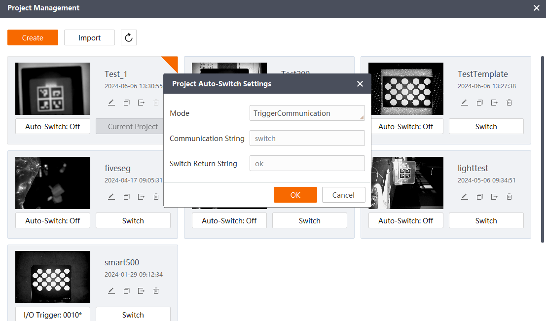
In the project management interface of the SCMVS interface, configure the newly created project. Select the project configuration switch, select the communication switch, and click OK.
Set the project to run mode: