


Application Scenarios#
Multiple Scenarios#
If a camera needs to be used in multiple scenes, and the distance between the camera points in different scenes is more than 25mm different, it is necessary to establish multiple solutions to solve the problem of the same camera being used in multiple scenes. That is, when a camera works in different scenes, it is necessary to configure different projects for the camera in different scenes, and each project needs to set the camera parameters according to the actual scene height, and the configuration mode is still automatically adjusted, and then reconfigure the 2.5D Detection operator, set the registration point, and set the project as an external communication trigger. The robot side is equipped with 2.5DDetectionSmart process blocks, which can correspond to different vision projects.
Single Scenario#
If a camera needs to be used in different stations, and there is a height difference of 25mm from the identification code of the photo point under different stations, the same set of camera parameters can be used to operate, that is, you need to add 2.5D Detection operators under different branches, and import the calibration file (.json) of the first 2.5D Detection operator to save the configuration, and then only need to set the datum again, save the configuration, and import the current configuration of the 2.5D Detection operator.
Note
The difference between multiple scenarios and single scenario is that the height between the camera and the marker code changes greatly, and the camera cannot work stably at different heights with large changes, so the camera parameters need to be set at different heights to make the camera image clear, and setting different parameters requires reconfiguration (i.e., calibration and registration) of the 2.5D operator.
Keep in mind that a branch control is configured under different stations, and different branch controls use different communication call characters, as shown in the following figure.
Single Scenario Example#
In add Tools, select the Logic tool, and then select Branch Control.

Click the + sign next to the branch control operator to add the 2.5D Detection operator.
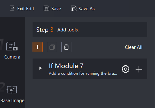

Different branch control represents different stations, and each needs to add a 2.5D Detection operator.

Next, the branch control operator will be configured, and different branch control operators will input different trigger characters.
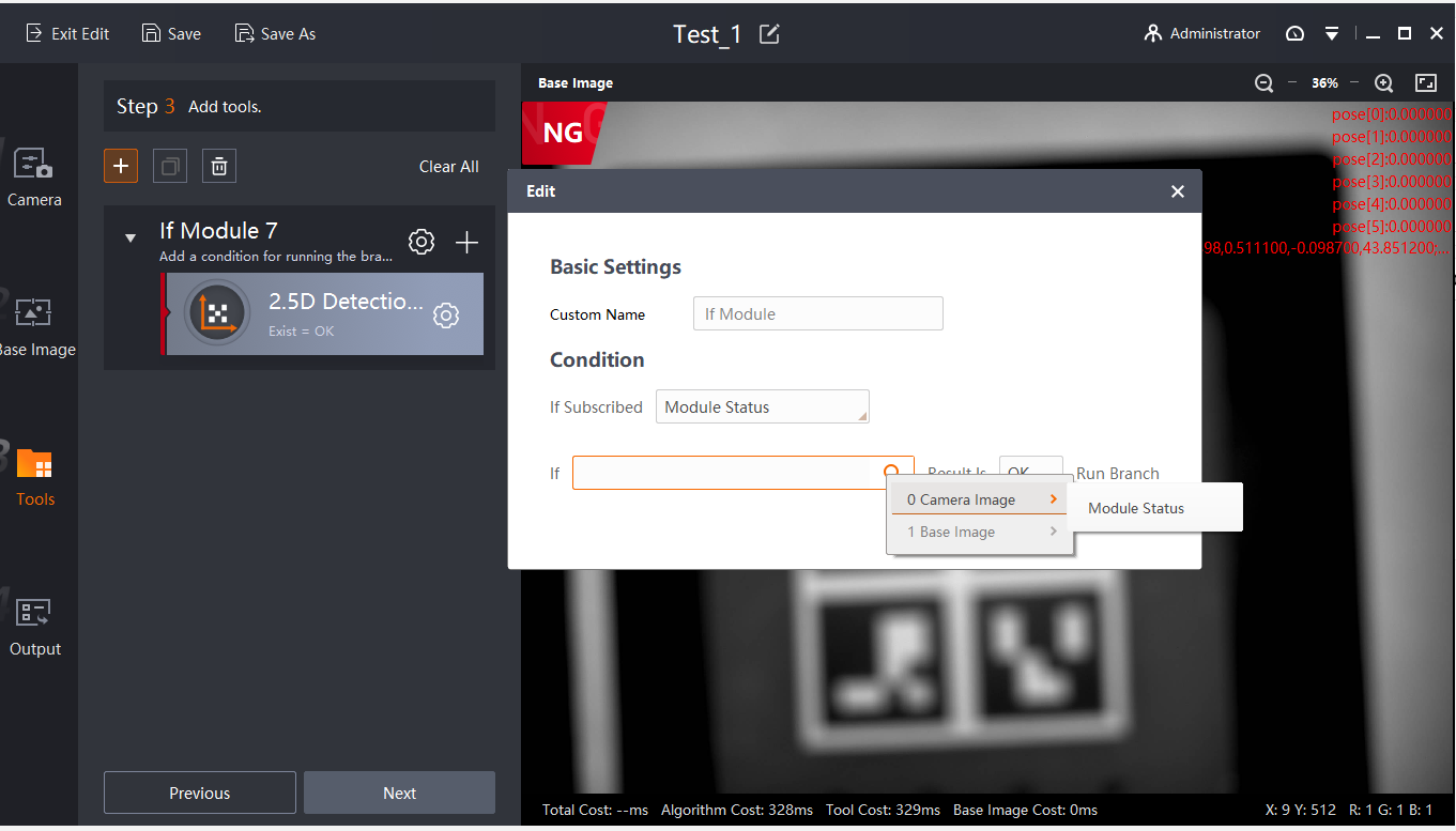
Communication string configuration, select camera image -> communication input string -> input the string that controls the operation of the branch, here this string should be distinguished, because the configured string needs to be entered on the robot side.
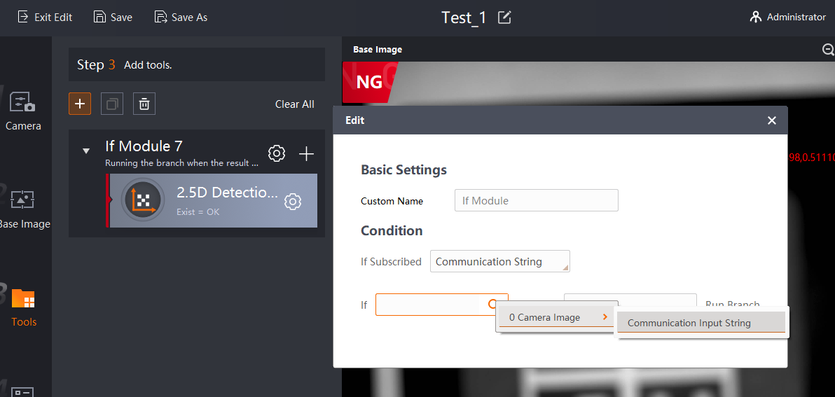
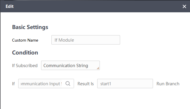
Different branches choose different strings to control, as shown below.


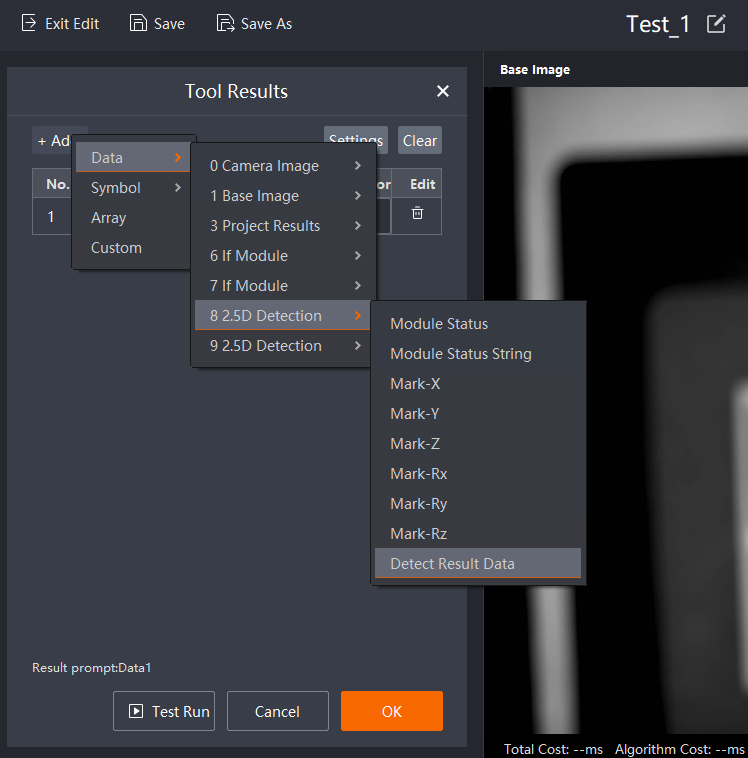
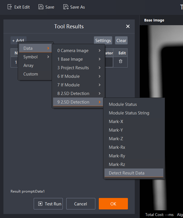
To configure the output, you need to output the results of all 2.5D Detection operators under branch control. When the robot executes that branch, the 2.5D Detection operator result under the control of the branch will be output, and the 2.5D Detection operator result under the control of the other branch is also empty.
As for how to use branch control on the robot side, as shown in the figure below, you only need to start (control the running string of the project) + space + start1 (the running string of the control branch 7) to control the operation of the 2.5D Detection operator under the branch control 7 of the project.

Summary#
Summary of using multiple stations for the same camera (if multiple cameras can be reused with one camera)
If the difference between the photo height (i.e., the height of the camera and the marker code) is less than 20mm under multiple stations, then a scheme can be configured by configuring multiple branch controls (representing different stations), and the communication string of each branch control can be configured at the same time. Configure the 2.5D Detection under the control of different branches (only the datum registration can be configured), import the saved configurations of the 2.5D Detection under different branches, and configure the output of all 2.5D Detection, and the camera solution configuration is completed here. In the 2.5D Detection plugin on the robot side, write “trigger communication string (start)” + “space” + “branch trigger communication string (custom)” in the scheme configuration to trigger 2.5D Detection under the control of a branch under the scheme.
If there is a large difference between the photo heights (such as greater than 20mm) under multiple stations, it is not possible to use one solution to cover all stations, and a new scheme can only be established under each station, that is, according to the scheme configuration process (camera configuration - datum map - application tool - output configuration, etc.), and the 2.5D Detection plugin on the robot side can trigger the corresponding scheme to work only by writing “trigger communication string (start)” at the scheme configuration.