Quick Start#
First Boot#
When starting up for the first time, the configuration information of robot in the control cabinet is needed to import. The specific steps are as follows:
The system displays ‘Welcome to use DUCO Collaborative Robot’ by default when you start up showing in the ‘Start’ page.
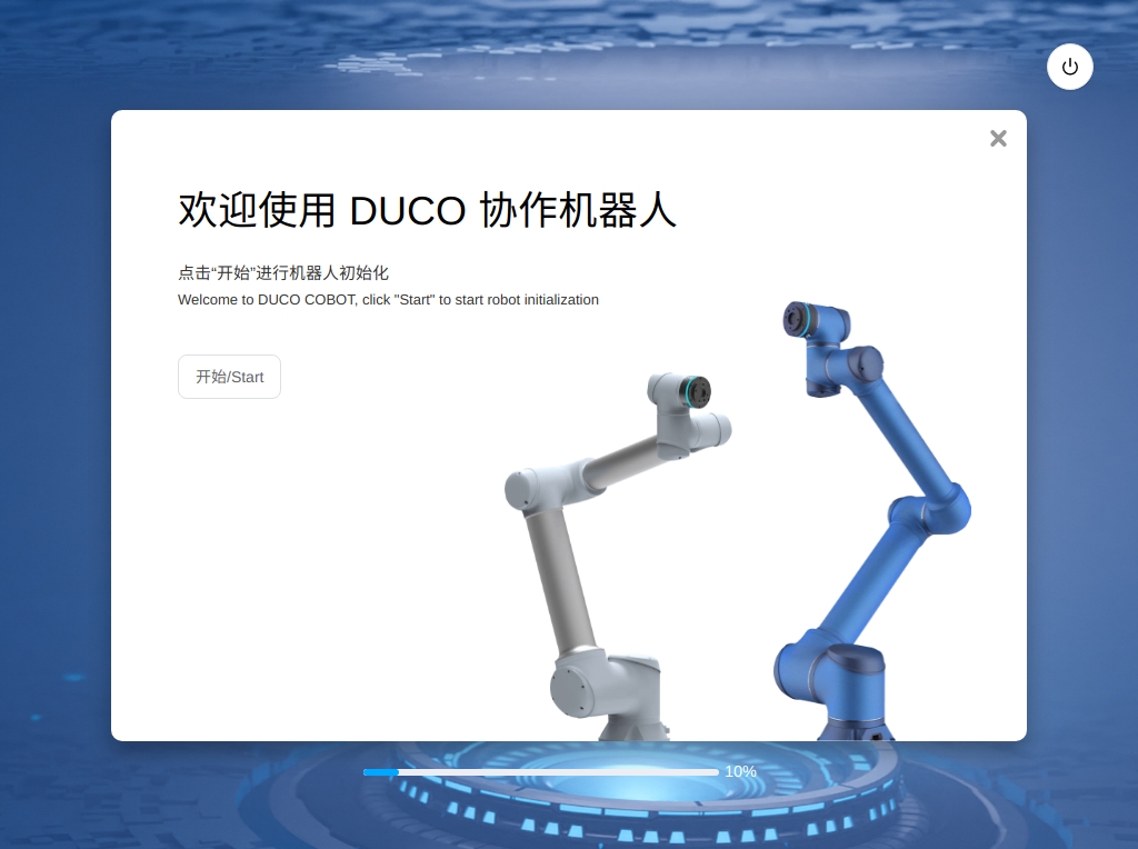
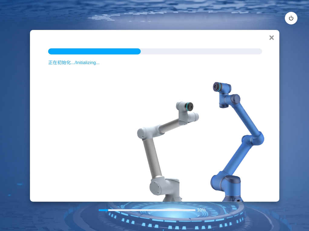
Click the ‘Start’ button to initialize the robot. ‘Initializing…’ is displayed in progress bar. When initialization is complete, the system displays ‘Initialization Completed’.
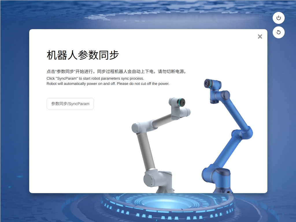
After the initialization is complete, enter the robot parameter synchronization page and click ‘Parameter Synchronization’ button. The robot process as follow steps: powers on, synchronizes parameters, and powers off.
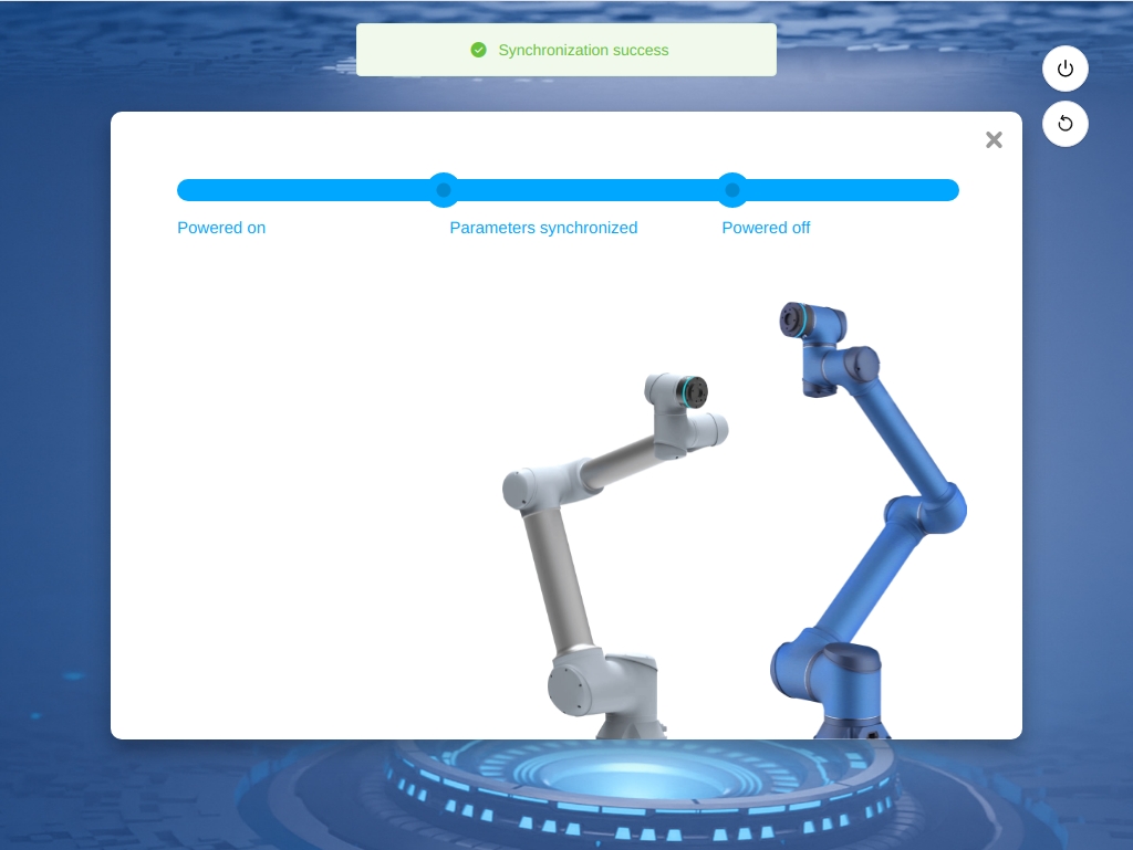
After the synchronization is successful, the page for setting safety parameters is displayed.
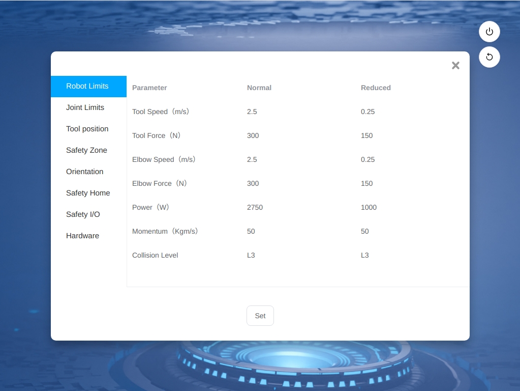
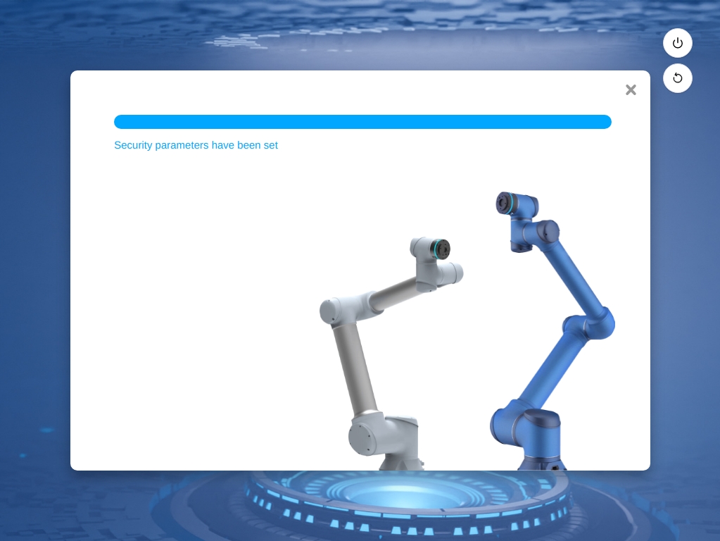
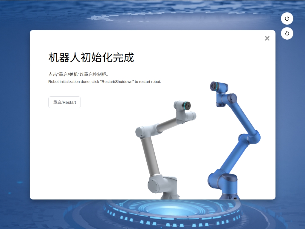
After confirming that the safety parameters are normal, click ‘Set Safety Parameters’. After the safety parameters are set, the robot is initialized and the control cabinet is restarted according to the prompts.
Booting and Login#
Users can connect to the control cabinet using an teach pendant or their own mobile device. The robot can be accessed from a web browser (Chrome is recommended) when using a mobile device. Connection methods contain as below:
Teach pendant connection: Directly insert teach pendant, the system will automatically start the interface program.
Wired connection: After connecting the PC to the control cabinet using a network cable, enter the IP address and port number 7000 in the address box of the browser, (e.g. 192.168.1.10:7000 (you can change the IP address in ‘System Settings’ function)) with the default IP address is DHCP Dynamic Allocation。
Wireless connection: After starting the power supply of the control cabinet, use the mobile device or PC to search for the wireless network ‘DucoCobot_xxxxx’ (the last five digits of the SN of the control cabinet), enter the default password ‘1234567890’, and connect to the network (the wireless network name and password can be modified in ‘System Settings’ function). Type http:duco-cobot.com:7000 in the browser address bar.
After entering the address to confirm, wait a few seconds to enter the login interface, as shown in the figure.
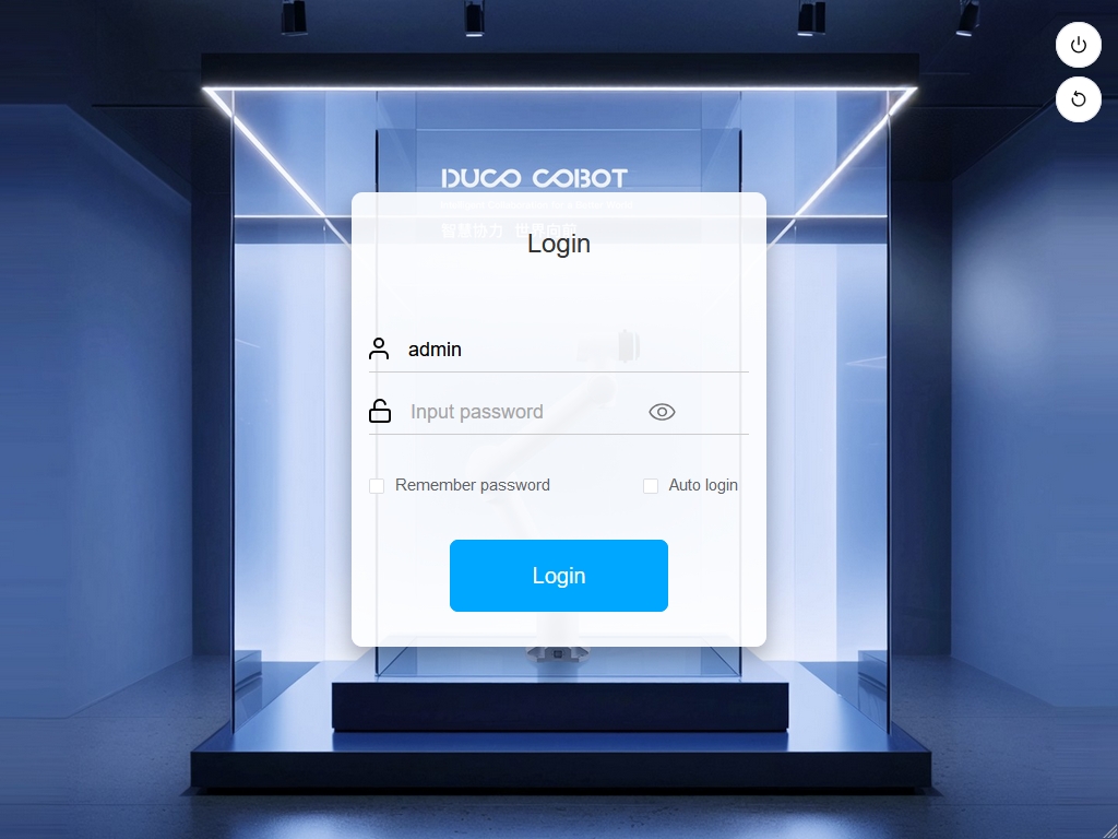
In the upper right corner of the login interface are the ‘Shutdown’ button and the ‘Restart’ button (for DC00 / DC15S/DC30D control cabinet), and in the middle is the area where the user enters the user name and password. The ‘Login’ button is above the ‘Remember Password’ and ‘Automatic Login’ options, users can choose to remember the password or automatic login. If the ‘Remember Password’ option is selected, the user does not need to enter the password to log in after logout, it is able to click the ‘Login’ button to log in directly; If the ‘Automatic Login’ option is selected, the ‘Remember Password’ option will be automatically selected by default. When the user enters the login page after shutdown or restart, it will automatically enter the system overview page without needs to click the ‘Login’ button. After the user logs out or restores the factory settings, the ‘Automatic Login’ option will be cancelled on the login page, and the user needs to manually click the ‘Login’ button to log in to the system.
Note
“Remembering password” and “automatic login” rely on the browser’s own functions. Changing the source of operations or changing the browser cannot retain the original settings.
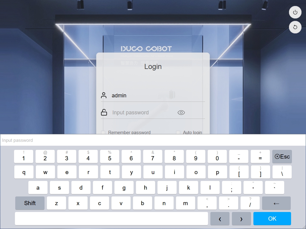
The default account username is default, the administrator account username is admin, and the password of both is 123. Click the user name or password input box, and the input keyboard will pop up at the bottom of the interface, as shown in the figure. After entering the user name and password (which can be normally entered through an external physical keyboard), click the ‘Login’ button to log in successfully. .
Robot Startup#
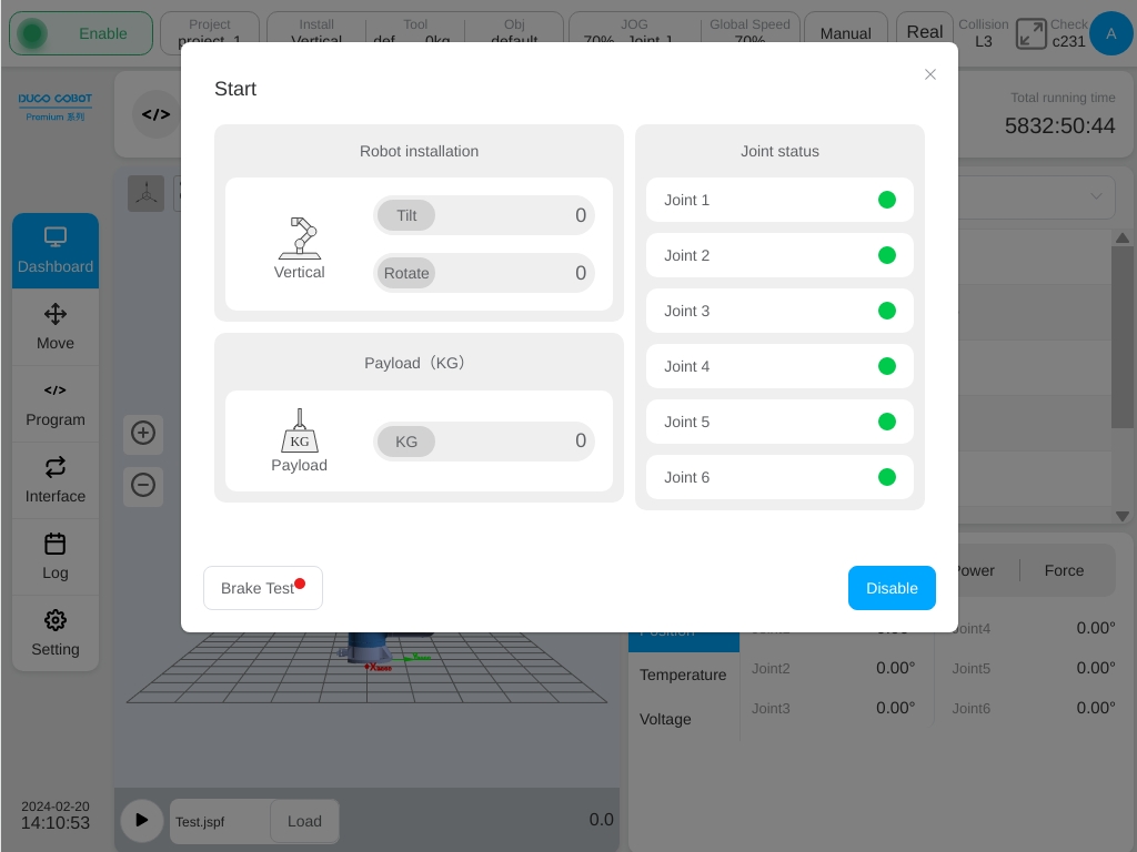
After successful login, the user enters the overview interface by default. When the robot is not powered on, the robot startup interface will automatically pop up, as shown in the figure.
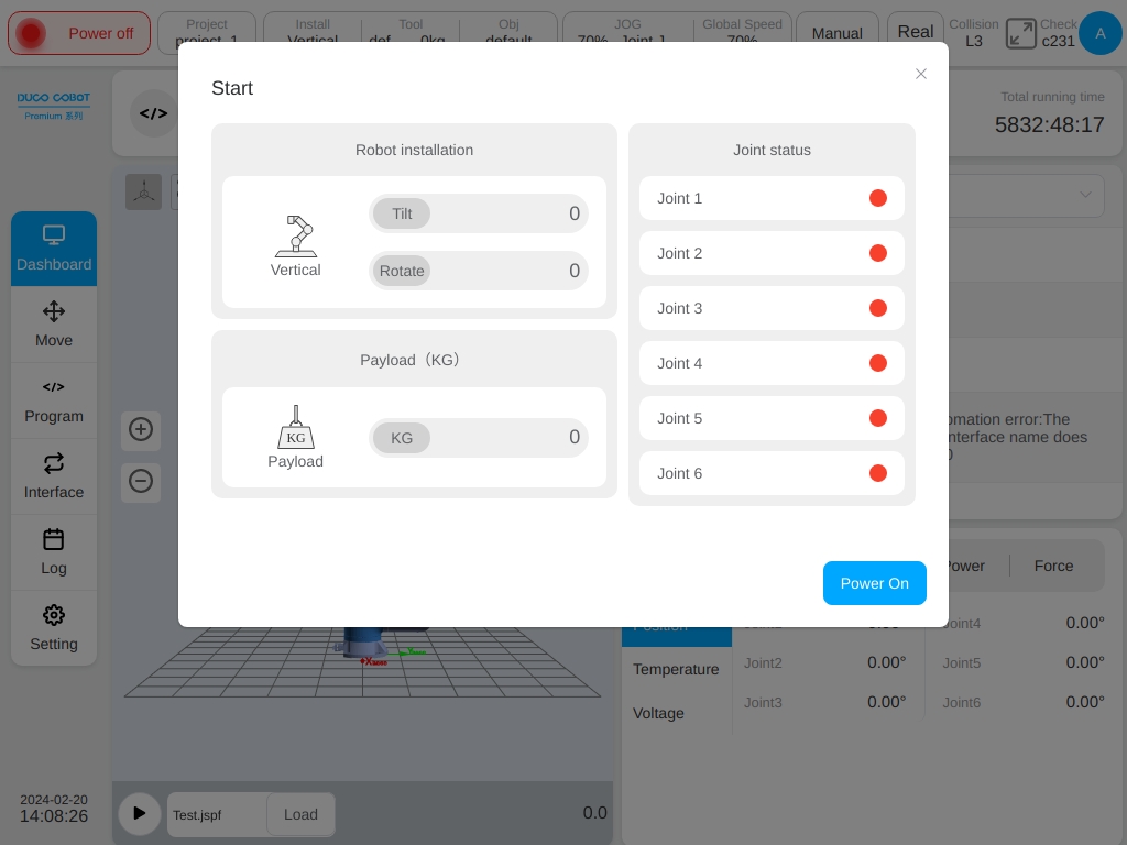
The left side of the startup interface displays the robot installation direction and end load information with the right side displays the robot joint status. When the robot is not powered on initially, the color of each joint status indicator is red. Click the ‘Power On’ button at the lower right corner of the startup interface the robot starts the power-on process.
When the robot is powered on, the joint indicator turns orange, indicating that the joint is powered on and the robot is powered on but not enabled. ‘Power Off’ and ‘Enable’ buttons will appear in the lower right corner of the interface, as shown in the figure:
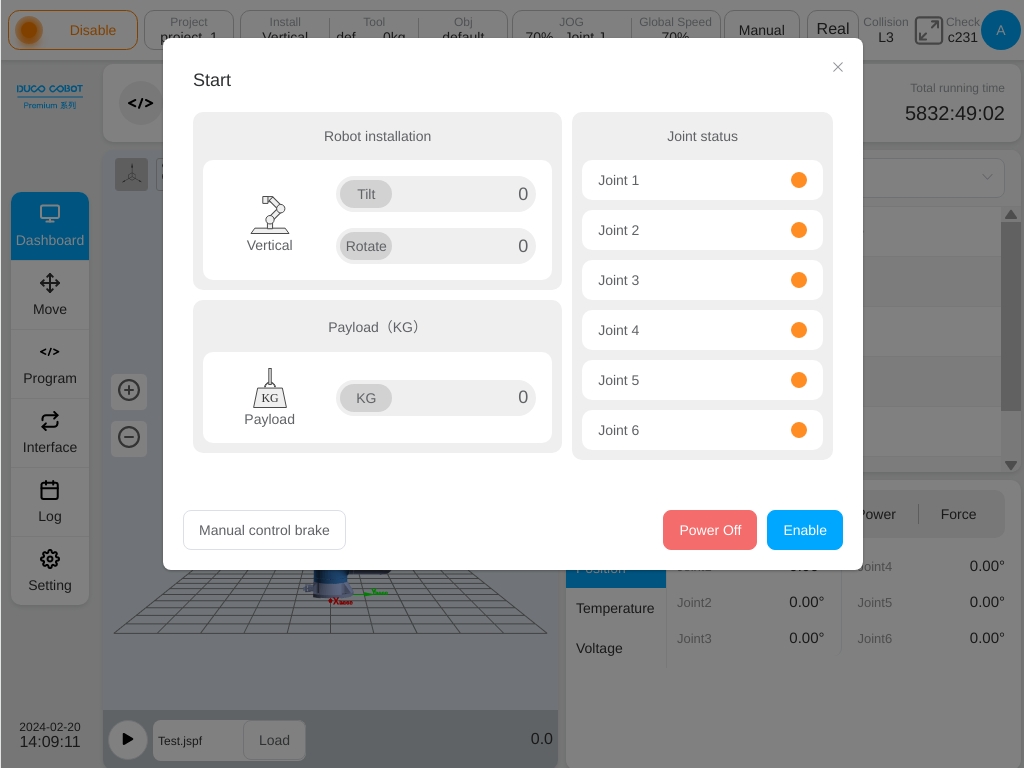
Click the ‘Power Off’ button, and the robot state will return to the initial state without power. Click the ‘Enable’ button to enter the enable state, as shown in the figure.
After each joint is enabled, the color of the joint status indicator is green. At this time, the robot enters the enabled state and completes the power-on process of the robot, as shown in the figure.
After the robot is enabled, the startup interface will automatically disappear.
Create a Program#
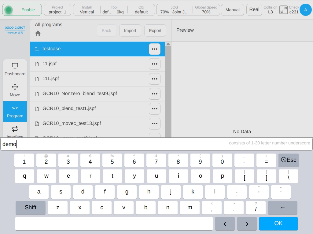
Click “Program” button in the left navigation bar to switch to the program page, click ‘New Program’ button at the bottom, and enter the program name: demo. Click ‘Enter’ button, that is, create a new program demo.jspf, and enter the programming page.
The demo program contains a ‘Start’ function block by default to set the starting waypoint of the robot. Doubleclick ‘Start’ button or singleclick “Parameters” button on the right to view and set the starting point.

Now we implement such a function: the robot moves to the ready point, moves down to an operating point, waits for 2s, sets the digital output port 1 to high level electronics, waits for 1s, restores the digital output port 1 to low level electronics, the process loops 3 times.
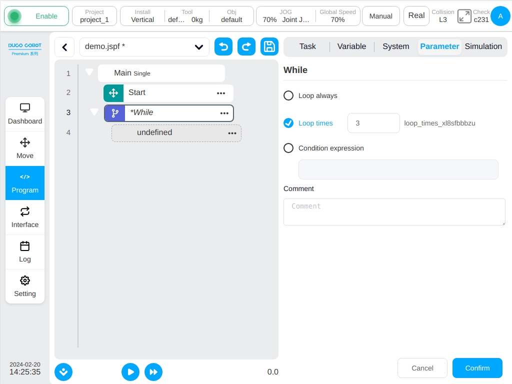
In the “Add” tab page – “Process Control”, find the ‘While’ function block, which can realize the cyclic process. Hold down and drag it to the left program tree, and then release it to add the ‘While’ function block to the program tree. Doubleclick the ‘While’ function block to configure its parameters, select “Number of Cycles”, and enter 3. Indicates that all program segments under the ‘While’ function block will be looped 3 times.
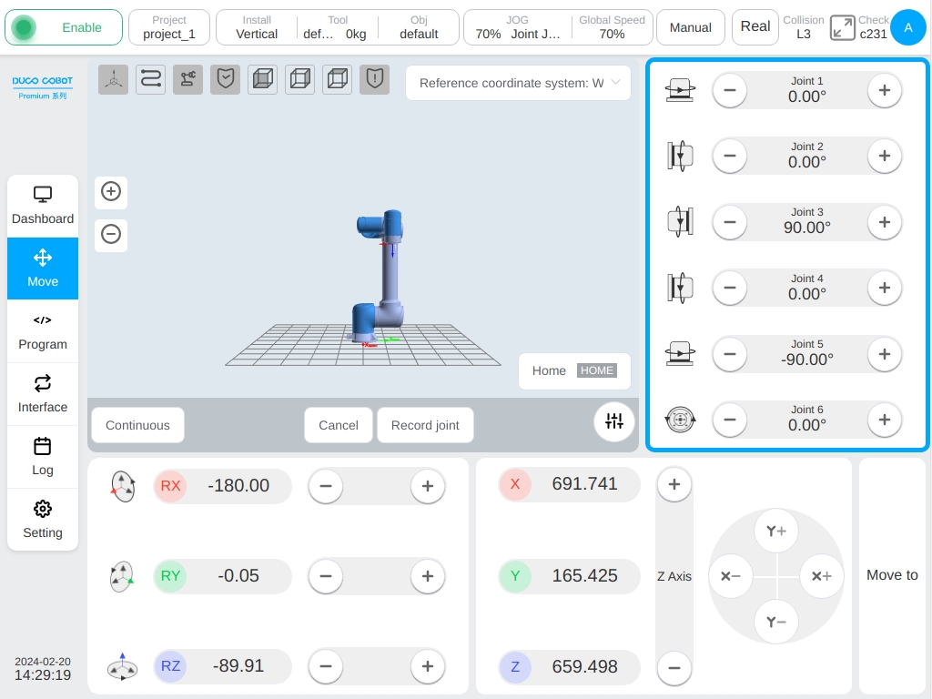
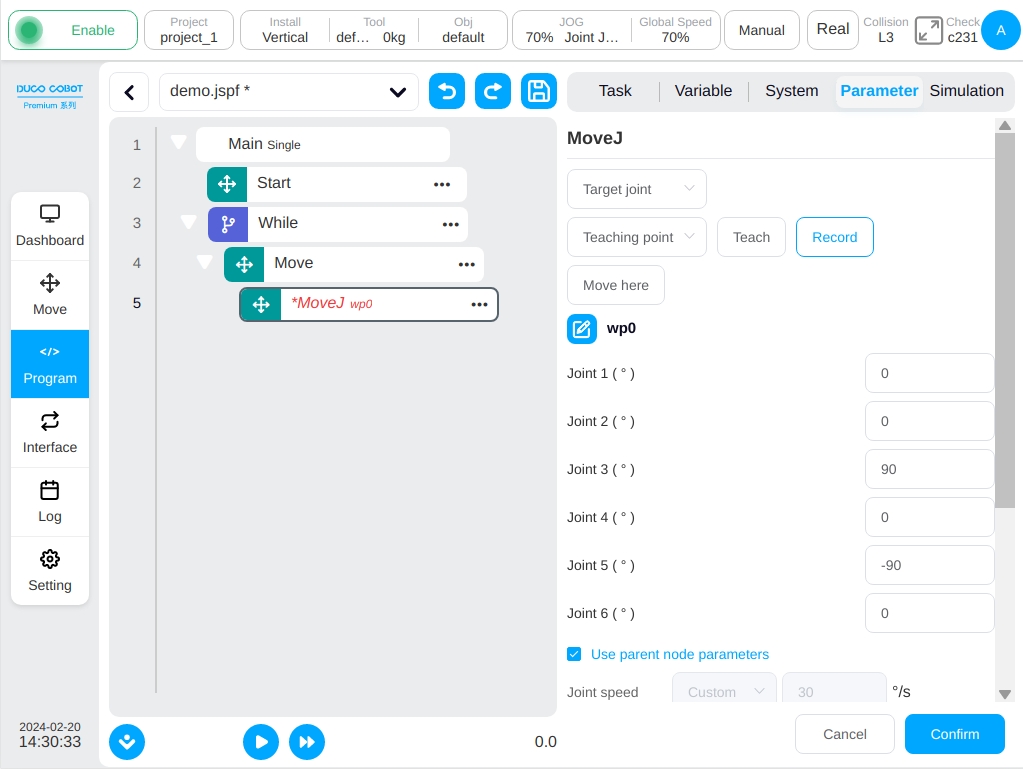
Find the ‘MoveJ’ function block in the “Add” tab page – “Move” and drag it to the subfunction block of ‘While’ in the program tree, as shown in the figure. Doubleclick the ‘MoveJ’ function block and configure its parameters. Click the “Select Point” button to switch to the point position of the mobile interface to teach the robot.
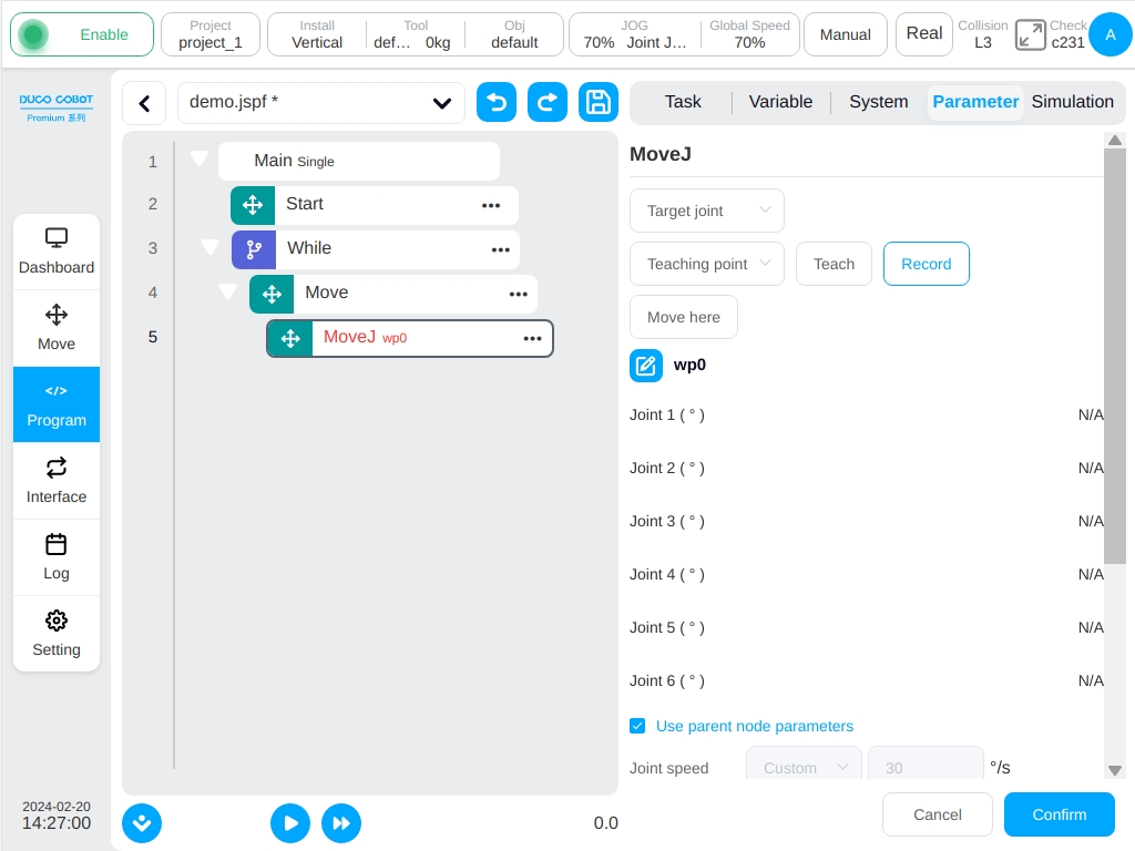
After the point position is set, click “Record Current Joint” button to record the current robot posture.
The set point information is displayed in the parameter configuration area of the ‘MoveJ’ function block. The joint angular velocity and joint angular acceleration can be further set. Click the “OK” button below to save the parameters of this function block.
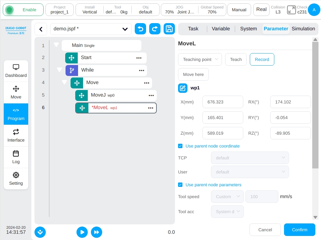
In the same way, add the ‘MoveL’ function block to the bottom of the ‘MoveJ’ function block and set the point.
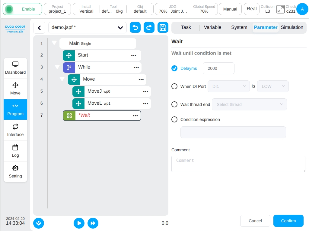
In the “Add” tab page - “Foundation” area, find the ‘Wait’ function block, drag it to the position as shown in the figure, select “Delay” function in its parameter configuration area, and enter the parameter 2000, which means that the program execution will delay 2s to execute the subsequent function block.
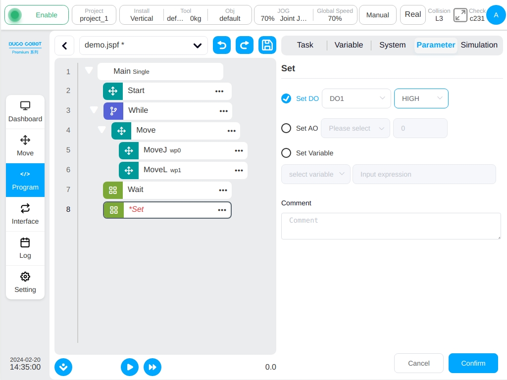
In the “Add” tab page - “Base” area, select the ‘Set’ function block and drag it under ‘Wait’ function block. In the parameter configuration area, select ‘Set Digital Output’ funciton and select DO1 and HIGH. Indicates that when the program executes to this function block, the digital output port 1 is set to high level electronics.
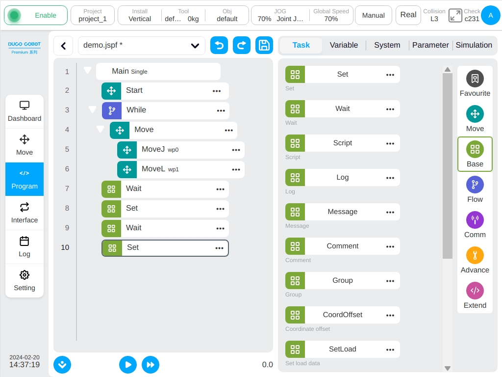
Similarly, add a ‘Wait’ block to Set the delay for 1s, and add a ‘SET’ block to set DO1 to LOW. The above is to complete the program of the function, click the “Save Program” button above to save the program.
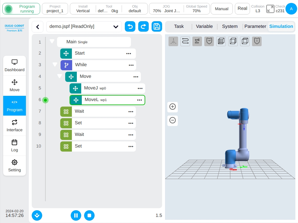
Run the Program#
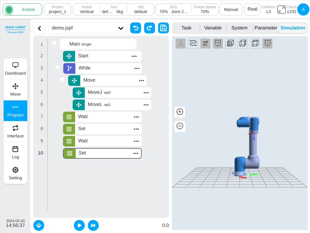
Switch to the ‘Run’ tab page and click the ‘Run’ button below. If the current position of the robot is different from the starting point of the program, the ‘Press and Move’ button will be displayed the starting position of the robot will then be displayed in 3D image. Long pressing the ‘Hold Move’ button to move the robot to the starting position. Click the ‘Run’ button again to run the program.
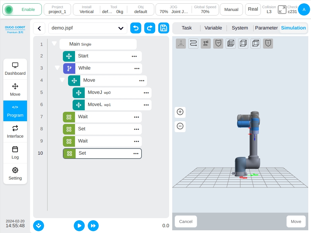
When the program is executed, as shown in the figure below, the green dot in front of the program tree is used to indicate the currently executing function block following with the currently executing function block displays a green highlighted border, and the real-time posture of the robot can be displayed in the 3D model. During the program is processing it is able to pause or stop.