


Status Bar#
The status bar of the interface header is shown in the figure.
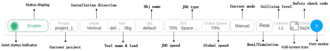
Joint Status Indicator:
For the initial not powered state of the robot, the indicator light is red; for the powered-up unenabled state of the robot, the indicator light is orange; and for the enabled state of the robot, the indicator light is green. The color of this indicator is consistent with the color of the joint status indicator in the startup interface.
Status Display Area:
This area will display three types of information: safety status, program status and robot status.
The safety status displays: Reduce mode, Recovery mode, Safety parameter configuration, Safety board firmware upgrade, Stop0, Stop1, Stop2, Safety board error and Robot firmware upgrade.
Program status display templates are: program stop, program execution, program suspension, program suspension, task execution;
Robot status display templates are: not powered on, not enabled, standby, firmware update.
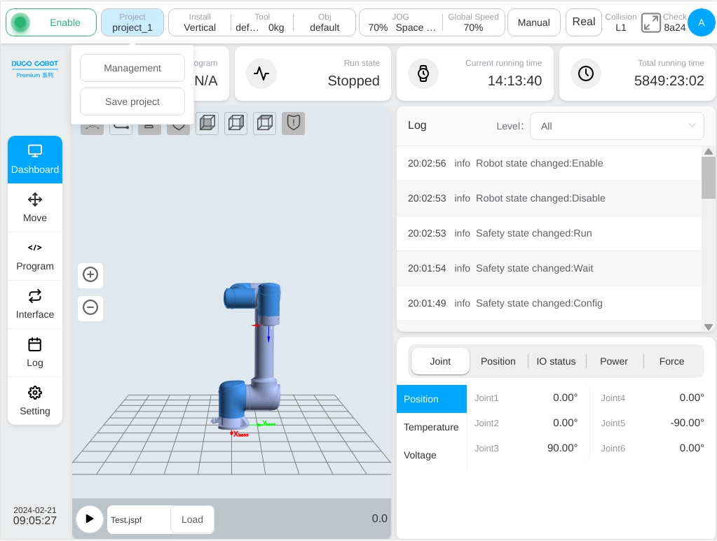
Project:
The current project name is displayed. Click the ‘Project’ button, a pop-up box containing ‘Project Management’ and ‘Save Project’ buttons will be displayed, as shown in the figure. In the project management section, the user can create, import, export, restore, save projects to the local computer, back up projects to the cloud, delete projects and modify project names.
Installation:
Displays the robot’s current installation direction and installation position description. Click the ‘Install’ display box to display the robot installation direction and installation pose, as shown in the figure.
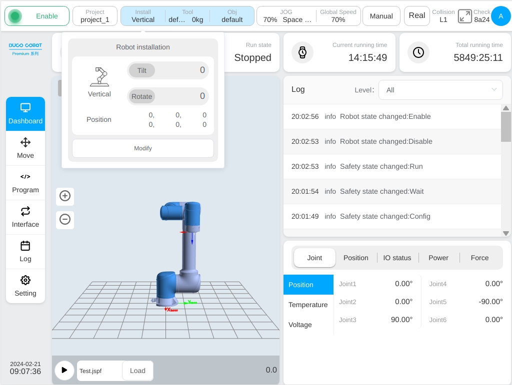
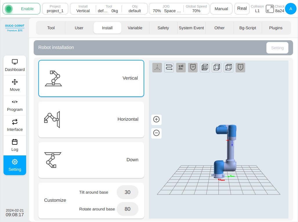
Click the ‘Modify’ button to get to the installation setting sub-page in the settings interface, as shown in the figure. The user can set the robot installation interface on this page.
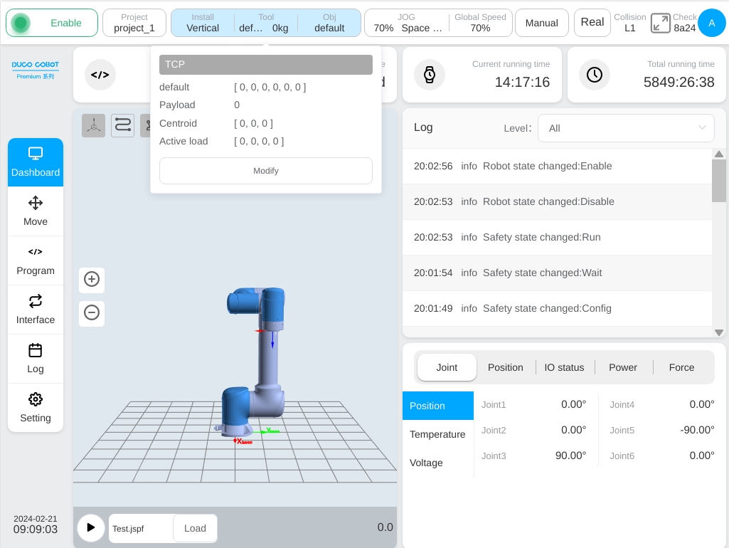
Tools:
Displays the robot’s current tool coordinate system name and load mass. Click the ‘Tools’ display box, and a pop-up box showing the relevant information of the robot tool coordinate system is displayed, as shown in the figure. Click the ‘Modify’ button to enter the tool settings sub-page in the settings interface, similar to the above to get to the installation settings interface.
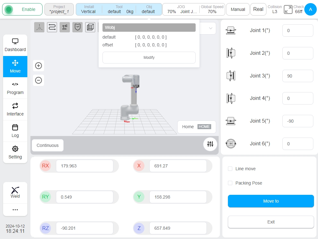
Workpiece:
Displays the name of the robot’s current workpiece coordinate system. Click the ‘Workpiece’ display box to display the robot workpiece coordinate system information, as shown in the figure. Click the ‘Modify’ button to enter the workpiece setting sub-page in the setting interface, similar to the above to get to the installation setting interface.
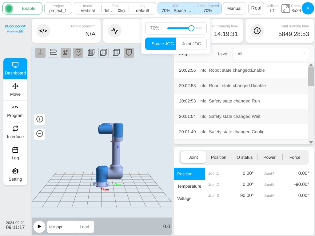
JOG Speed/Type:
Displays the percentage of the robot’s current JOG speed. Click the JOG display box to display the JOG speed adjustment slider and JOG type selection button to adjust JOG speed or manual input and to switch between spatial JOG or joint JOG. Note: It only affects the JOG speed of the robot at this startup, and the next startup fails. If you need to change the JOG speed at each startup, please set the default JOG speed in ‘Settings’ – ‘Other Settings’ – ‘Startup Settings’.
Global Speed:
Displays the percentage of the robot’s current global speed. Click the Speed display box to display the speed adjustment slider. You can adjust the global speed or enter it manually. Note: Only the global speed of the robot at this startup is affected, and it will fail at the next startup. If you need to change the global speed at each startup, please set the default global speed in ‘Settings’ – ‘Other Settings’ – ‘Startup Settings’.
Operation Mode:
Display robot operation mode, manual mode and automatic mode. Click the display box, and a pop-up box containing the ‘Manual Mode’ and ‘Automatic Mode’ buttons is displayed. Click the corresponding buttons to switch the operation mode. When the user switches between manual mode and automatic mode, the user needs to enter the current login password. After entering the correct password, the mode can be switched. When the physical hardware mode switching signal is enabled, the mode switching button in the interface is invalid.
True Machine:
Switch between real and simulation modes. The simulation mode can only be set when the robot is in enabled standby and the program is stopped.
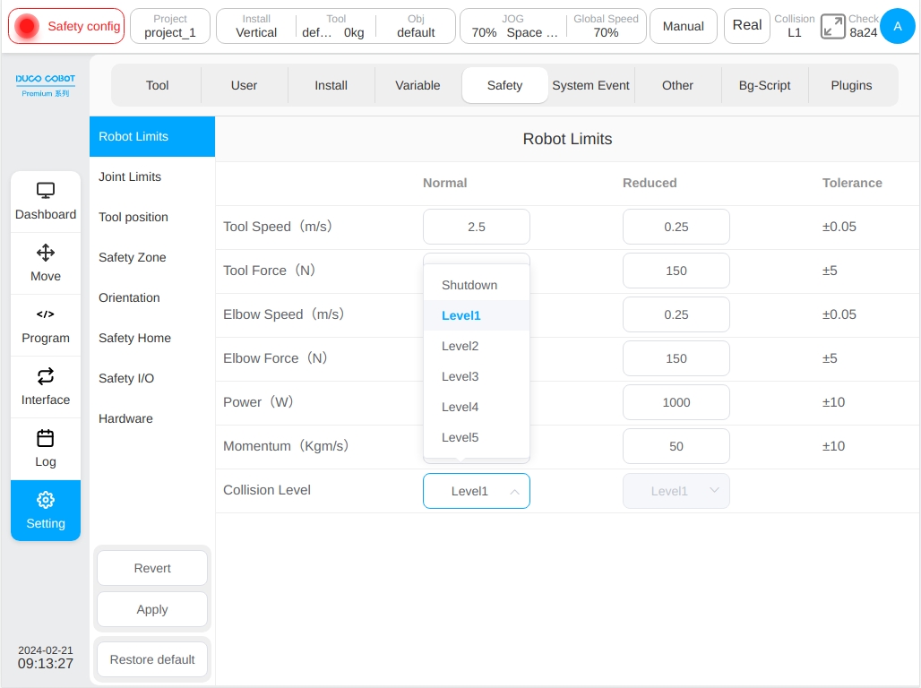
Collision Detection:
Collision detection displays the current status of the collision detection settings, as well as the safety level. See Section 6.3.2 for details on safety level settings.
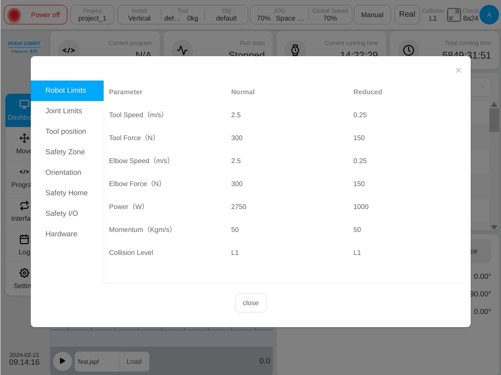
Safety Check Code:
The safety verification code is displayed. Click the safety verification area with the safety verification page is displayed, as shown in the figure. This interface displays the safety configuration parameters set under the Safety Settings subpage of the settings interface. To close the page, click Close at the bottom of the safety verification page or the cross mark in the upper right corner of the page.
User Profile Picture:
Displays the uppercase letter of the login user name. Click the user profile picture to display the pop-up box as shown in the figure. These buttons include Change Password (displayed for users other than admin), System Settings, Account Management (displayed only for users with admin rights), About, Help, Logout, Shutdown, and Restart.
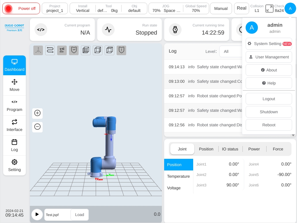
Click the ‘Help’ button, and a ‘Help Document’ window will appear, which can be used to query the error code.