Program Page#
Click the navigation bar “Program” to enter the program page. Program page can manage program list, edit program, run program.
Program List Page#
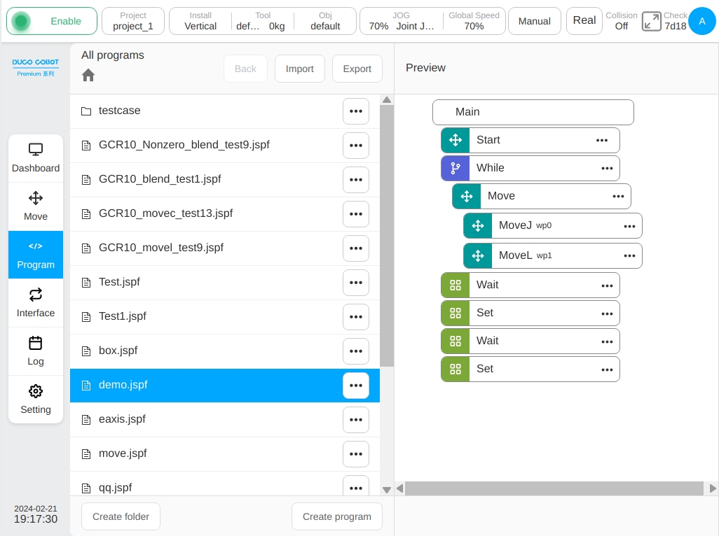
The list page is used to manage all programs in the currently active project. The figure is the program list page, showing all programs and folders under the program root directory.
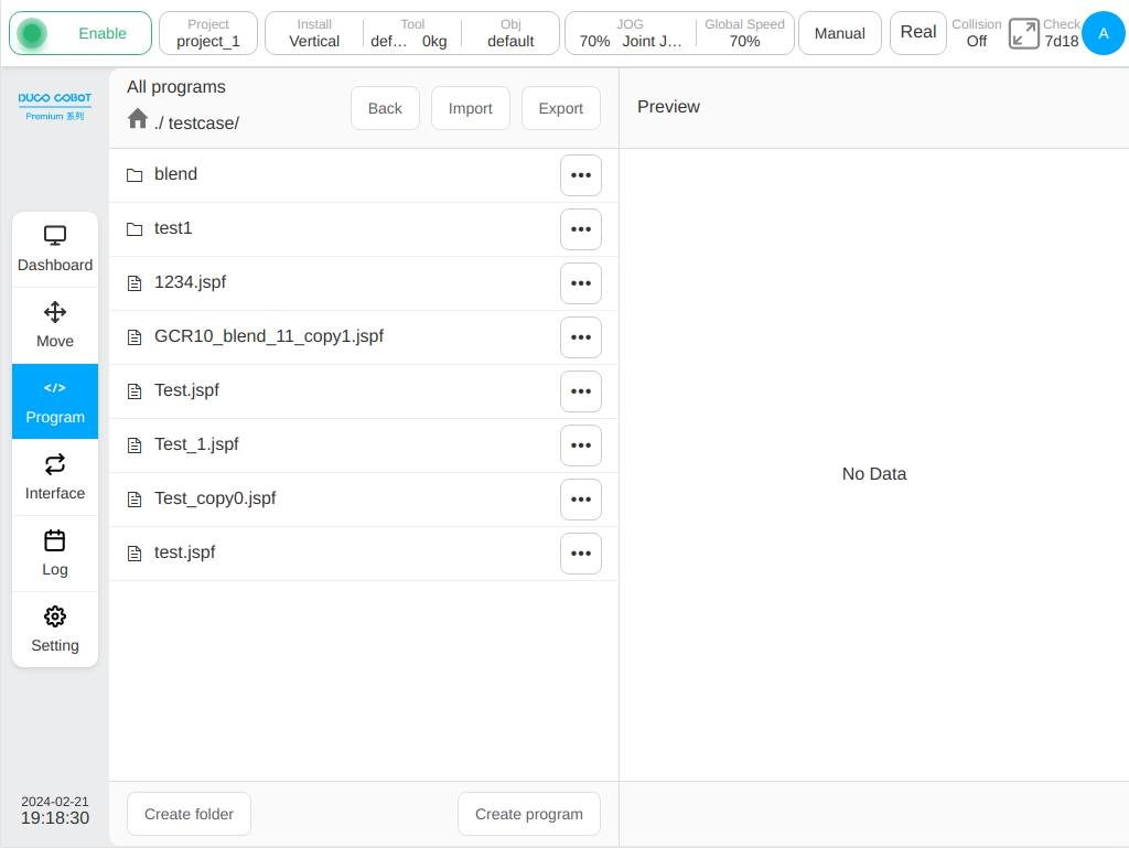
Select the folder and click the button on the right  Button, click “Enter program”, you can switch to the file directory, view all programs and folders under the folder.
Select the program, the right “program preview” area can display the program content, click “Enter the program” to open the program.
The current directory is displayed in the upper left corner, as shown in the figure. Click the “Return to the upper level” button to return to the upper level directory, click the path to switch directories, and click  to switch to the root directory.
New Program#
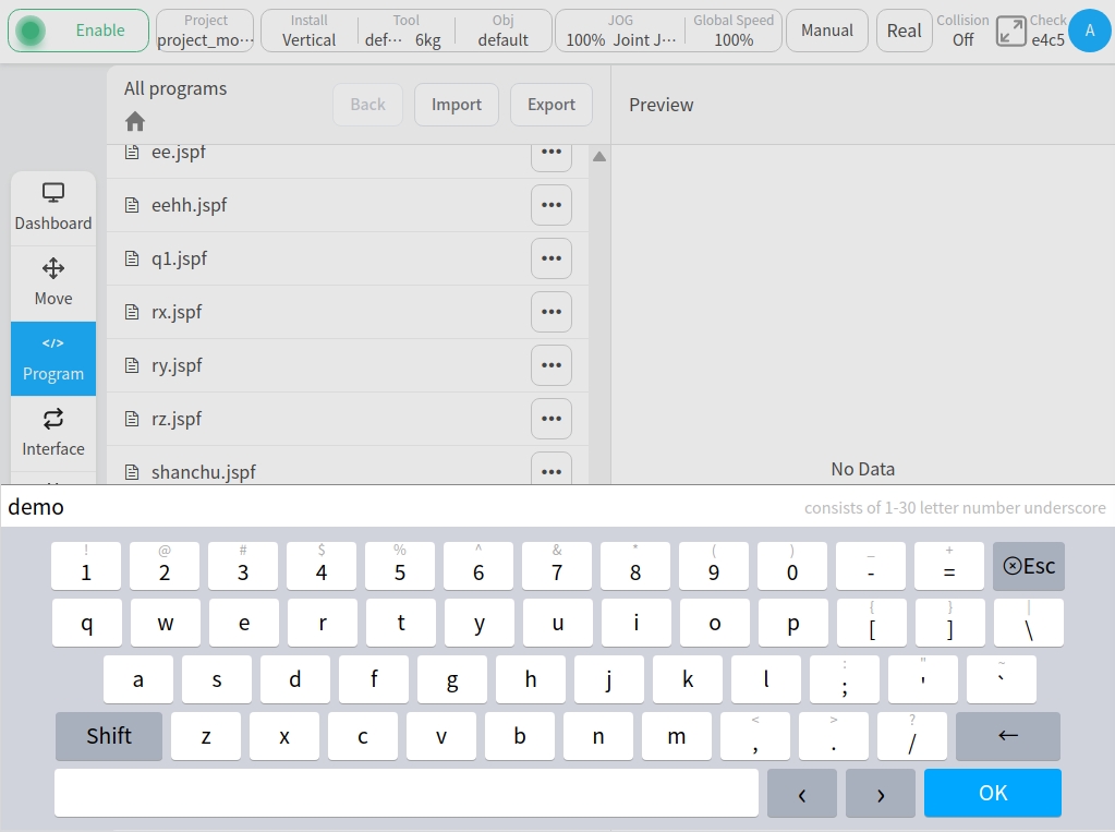
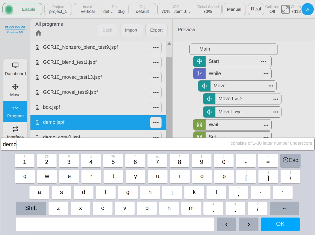
Click the ‘New Program’ button to pop up the keyboard, enter the program name, click the ‘OK’ button to create a program under the current folder.
New Folder#
Click the ‘New folder’ button to pop up the keyboard, enter the folder name, and click the ‘OK’ button to create a folder under the current folder.
Program File Action#
Click the button on the right of the list item to pop up the menu box as shown below:
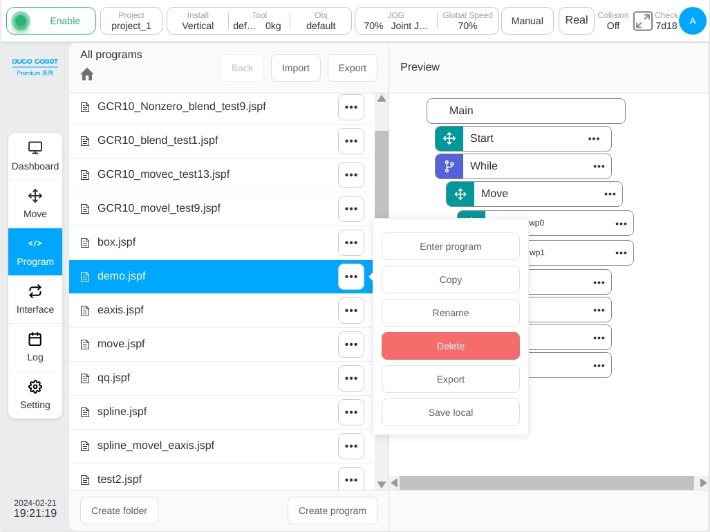
For program files, the user can do the following:
Enter the Program
Click to open the program.
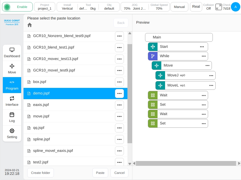
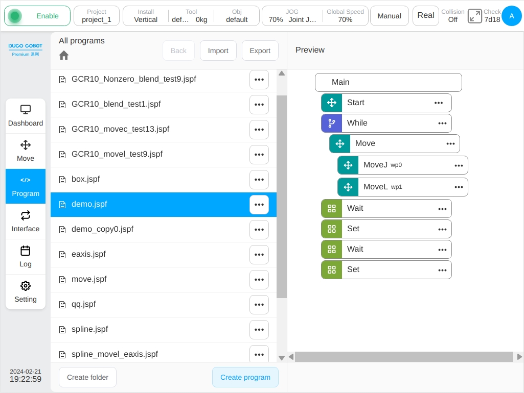
Copy
Click the ‘Copy’ button to copy the program file. The program list page is as follows. At this time, the user can select the location of the paste, click the ‘Paste’ button to copy the program to the current folder, and click the ‘Cancel’ button to cancel the copy. If there are files with the same name in the current folder, the suffix _copyXX is automatically added to the end.
Rename
Click the ‘Rename’ button, the keyboard will pop up, enter a new name, confirm it can be modified.
Note: Programs that are already open or running cannot be renamed.
Delete
Click the ‘Delete’ button, pop-up confirm dialog box, confirm to delete the program.
Note: Programs that are already open or running cannot be deleted.
Export
The program file can be exported to the U disk, see the program import and export.
Save to Local
The program file can be downloaded to the local through the browser.
Folder Actions#
Click the button at the right of the folder item Button, the pop-up menu can perform the following operations: enter the program, rename, export folder, delete
.
Enter the Program
Click to switch to this folder and view all programs and subfolders under this folder.
Rename
Folders can be renamed. Note: If there are open or running programs in this folder the rename function is forbidden.
Export Folder
The entire program folder can be compressed into a compressed package exported to the U disk.
Delete
The user can delete all contents in the folder. If there are open or running programs in this folder the delete function is forbidden.
Program Import and Export#
The user can import or export programs and folders from external devices to external devices. External devices refer to storage devices connected to the USB port of the control cabinet, such as USB flash drives and mobile hard drives.
Program/folder import
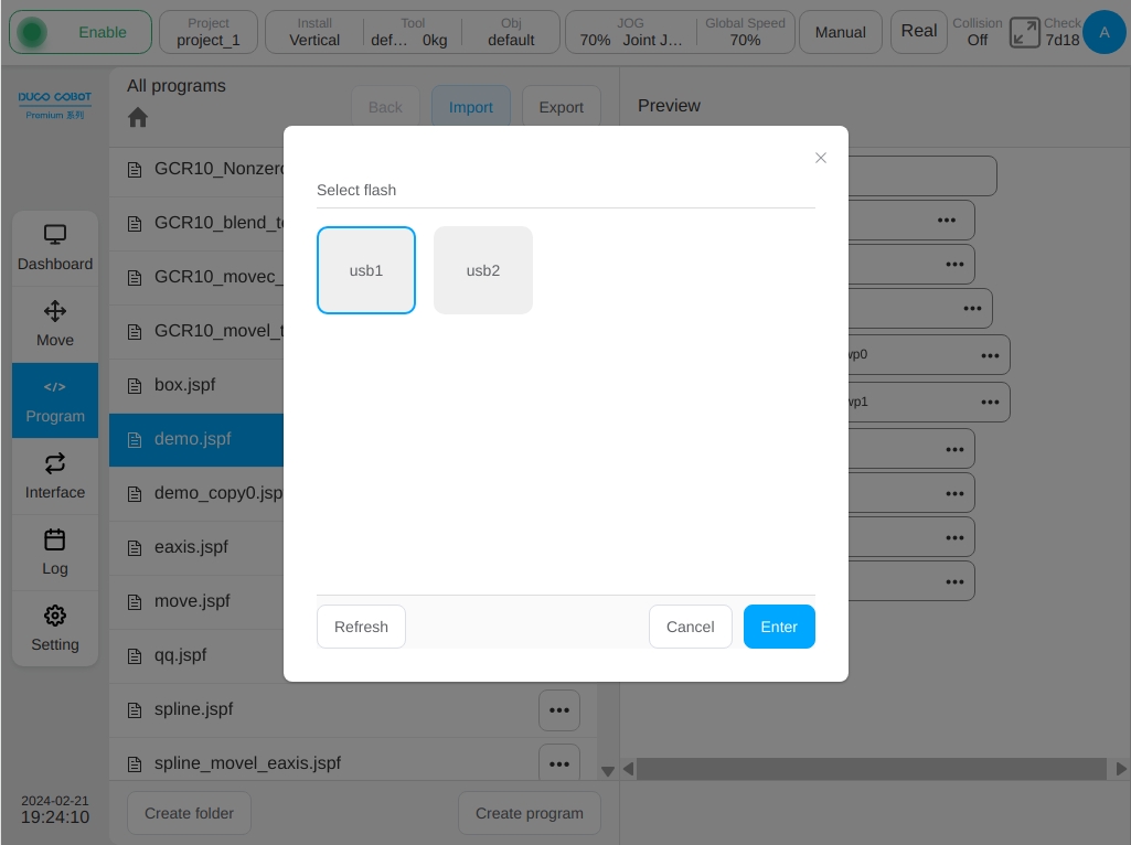
Click the ‘Import’ button, the following window will pop up, showing the USB storage device mounted on the current control cabinet and select a device.
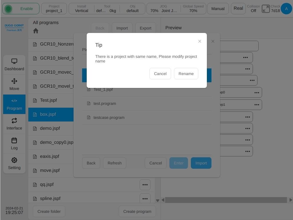
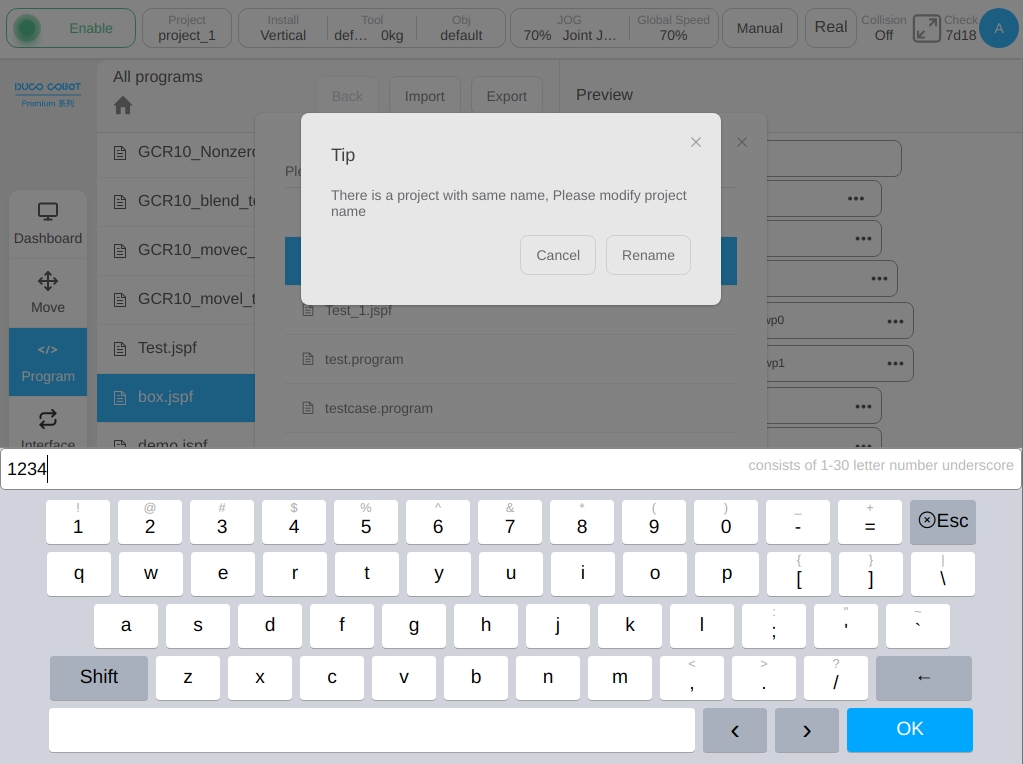
Folders in the device and eligible files (jspf, script, or program) are displayed on the page. Select a file and click Select to decompress the file or the compressed file package (program) and import it to the control cabinet. When importing a file, if the file name is the same as the program file on the control cabinet, a rename prompt box will be displayed and the file will be imported to the control cabinet after being renamed.
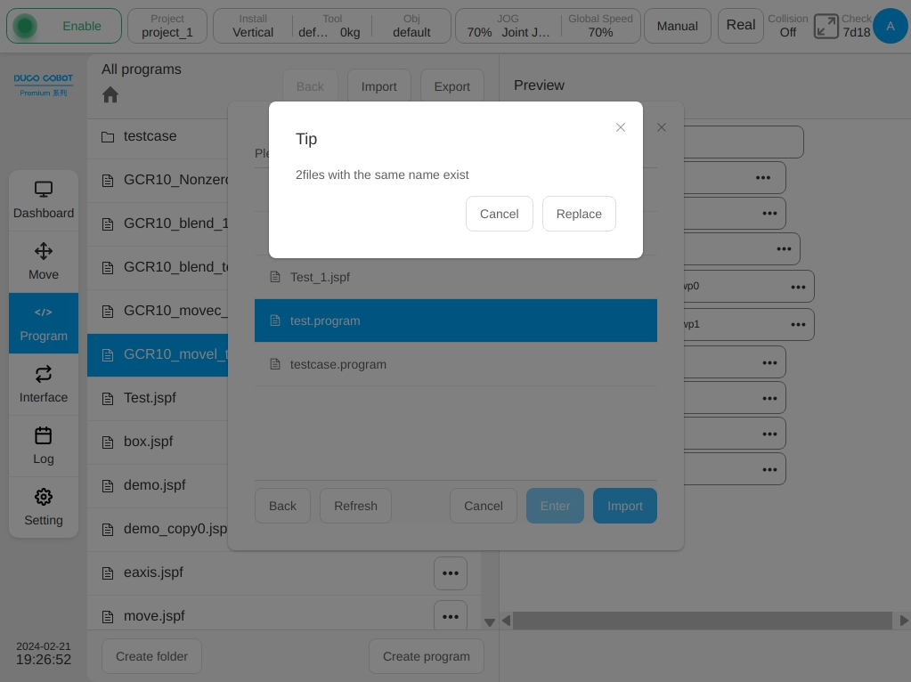
If a file with the same name exists when the user imports a folder (program), the system displays the number of files with the same name. The user can click ‘Cancel’ or ‘Overwrite’.
Program/folder export
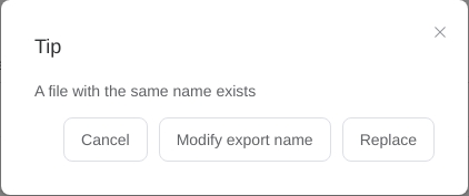
Select a program on the program list page and select the ‘Export’ button in its interactive menu to perform the export operation. Similar to importing, a pop-up window displays the USB storage devices mounted on the current control cabinet. After selecting a device, the user can view the files and folders of the device, select a folder to export and export the program to the folder of the device. If the exported program file has the same name as the file in the device, the following window is displayed. The user can cancel the export, change the export name and export the file again, or directly overwrite the file in the device. If a folder is selected, the system names the folder, packages the folder, and compresses it into Folder Name. program. The compressed package contains the folder of this level.
Click the ‘Export’ button at the top of the program list page to package all files and folders in the current directory into a compressed package named ‘Current program list Name. program’ and export the package to the specified path on the external device. The compressed package does not contain this level folder. Similar to the export program, when a file with the same name exists, the operation prompt box with the same name will be played.
Programming#
Overall Layout#
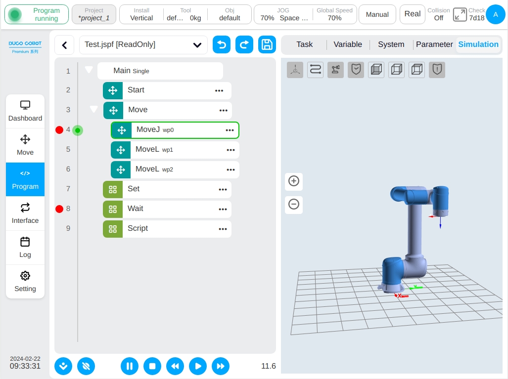
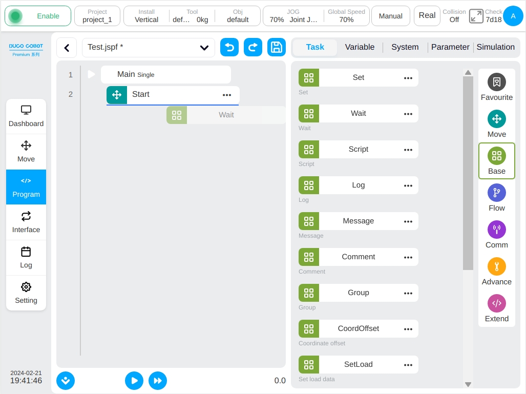
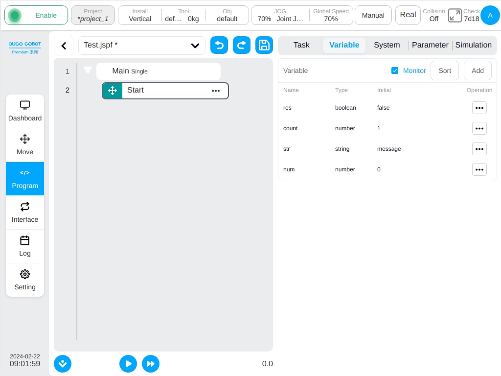
After creating a new program or opening a program on the program list page, the user can enter the programming page, as shown in the following figure.
The left side of the programming page is the programming area where the program tree can be edited. The right side can be divided into five sections: the ‘Commands’ tab is the function block list area which shows the available graphical programming function blocks; the ‘Program Variables’ tab is the program variables area, which allows the user to create program variables, monitor them while the program is running, and sort the names of program variables alphabetically, as well as select whether or not to monitor them; the ‘System Variables’ tab shows the initial values of system variables, as well as whether or not to monitor them. The ‘Program Variables’ tab is the program variables area, where you can create program variables, monitor program variables while the program is running and sort program variable names alphabetically, as well as choose whether or not to monitor the variables; the ‘System Variables’ tab is the area where the user can display the initial values of the system variables and monitor the current values of the system variables while the program is running, and likewise sort the system variable names alphabetically; the ‘Parameters’ tab is the parameter configuration area, where the user can view and edit the parameters of the selected function blocks in the program tree; the ‘Simulation’ tab shows the 3D model of the robot.
Therefore, click the right side of any type of function block in the list area of ‘Move’, ‘Basic’, ‘Flow control’, ‘Communication’, ‘Advanced’, ‘Extension’ in the ‘Instruction’.The icon can pop up the operation dialog box, click the ‘Add to Common’ button in the operation dialog box, the user can add the instruction block to the ‘Common’ class; Click to the right icon of the feature block in the Common class Feature Block list area will also pop up the operation dialog box, click the ‘Remove’ button in the pop-up operation dialog box, the user can remove the command block from the ‘Commonly used’ class.
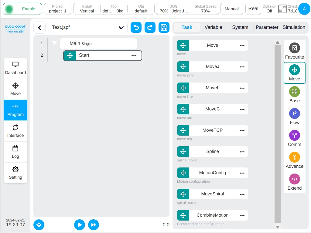
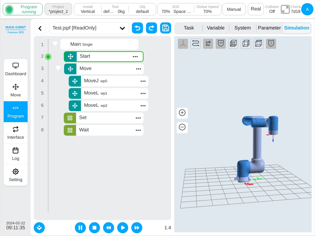
The name of the current program is displayed at the top of the left and the * after the program name indicates that the program has changed. Click any area of the display box where the program name is located. A drop-down box will appear below the display box to display the list of open programs.
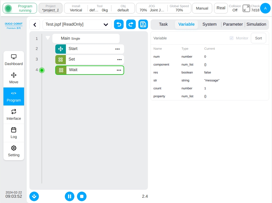
As shown in the figure above, the list of open programs shows that there are two open programs in the current system, where the program that shows a green circle before the program name is the running program.
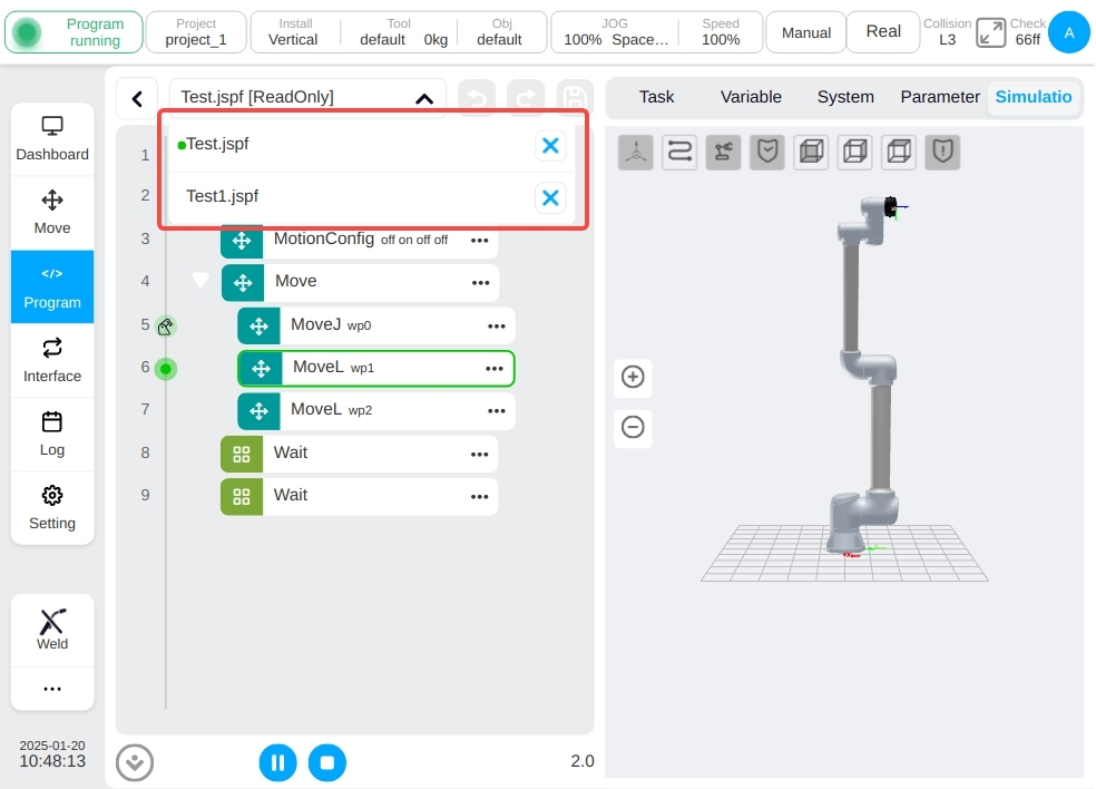
Click button in the drop-down box to the right of the name  to close the program; Click the drop-down list item bar to switch to the corresponding program.
Note
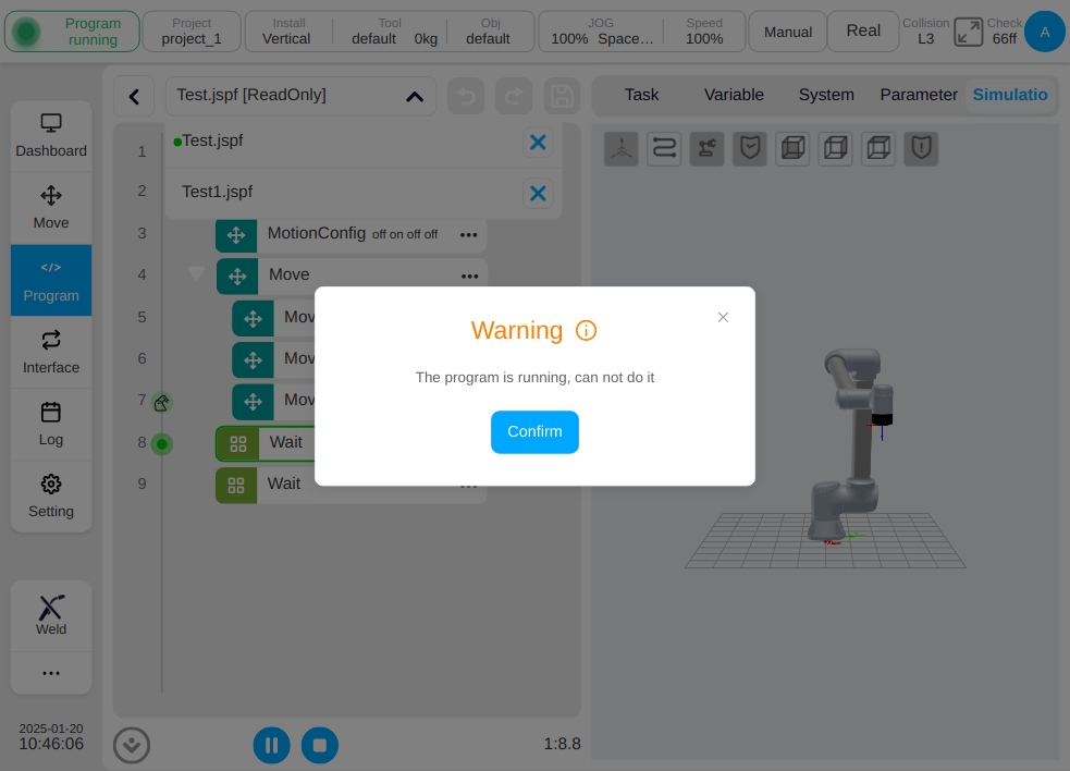
Note: Running programs are not operable to close programs! A pop-up window will prompt you as shown below.
When the user close the program, if the program changes, a dialog box will pop up asking the user to save the program or abandon the modification. When you switch to view other programs while the program is running, the following image is displayed at the bottom of the page.
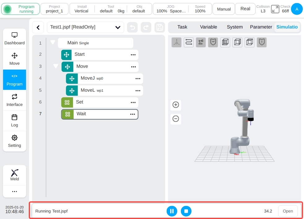
On the left side, the name of the program currently running is displayed, and in the middle is the operation buttons such as program pause, resume, and stop, and click the “View” button on the right to return to the currently running program.
Programming Actions#
Programming uses drag-and-drop and double-click additions.
Drag Method: The user can hold down the function block in the function block list area and drag it to the programming area. A blue horizontal line will be displayed at the corresponding position of the program tree, indicating that the function block will be inserted there. Loosening adds a function block there. If a red line is displayed when the user drags a function block to the corresponding position in the program tree, the function block cannot be inserted there. After releasing the function block, a dialog box will be displayed.
Double Click Add: Click any function block in the program tree to select the function block. At this time, double-click the function block in the list area with the function block in the list area will be added to the program tree below the selected function block. (Note: Double click is not supported on mobile devices),
Supports directly dragging function blocks in the program tree to other locations.
Select a function block, manually switch to the parameter configuration area and set the parameters of the function block. For details about each function block and the corresponding parameter configuration page, see the following.
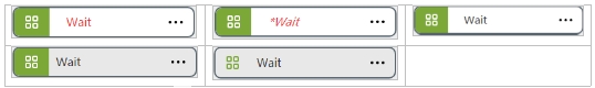
The function block in the program tree has the following five states. Red indicates that the function block is not configured with valid parameters; * in italics indicates that the parameter of the function block has changed, but it is not saved to the program tree; The black body indicates that the parameters of the function block are valid and unchanged. The gray part of the function block indicates that the state is selected for dragging and dropping. If all function blocks are gray, the function block is disabled.
Click the right icon of the program tree function block.The dialog box contains the following operations
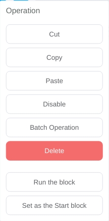
Cut: Cut the function block.
Copy: Copies the function block.
Paste: The user can paste the copied function block to the bottom of the selected function block.
Disable/Enable: Click to select whether to enable the function block, select disable, the function block gray, the program will not execute the function block.
Run the block: Click to run the target function block.
Note
When using the Run the block function, since the program before the selected program will not be executed.So if target function block includes any parameters defined by variables, the value of the variable will be based on the current value of the variable at the time of using the Run the block function.
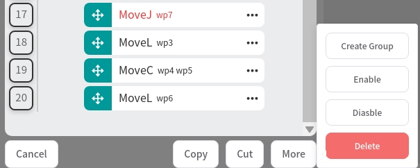
Batch Operation: Function blocks can be copied, cut, deleted, disable, enable in batches and create group. If the user select any function block for batch operation, the icon  is displayed within the line number of the function block.
If the selected icon is displayed next to the row number of a function block of the same level as the function block, all function blocks between the function block and the original function block are automatically selected. In addition, only function blocks of the same level can be selected. Function blocks that cross the parent level cannot be selected.
Batch Copy: Copy selected blocks and paste to the selected position
Batch Cut: Cut selected blocks and paste to the selected position
Batch Enable: Enable all selected blocks
Batch Disable: Disable all selected blocks
Batch Delete: Delete all selected blocks
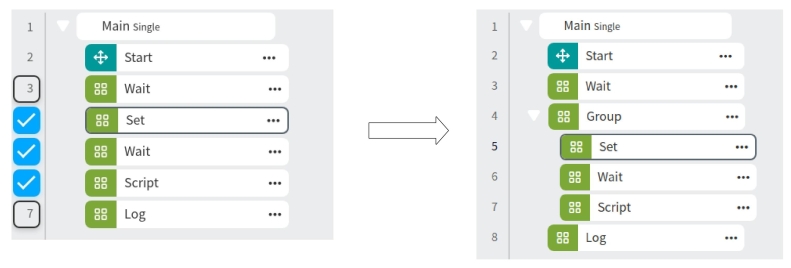
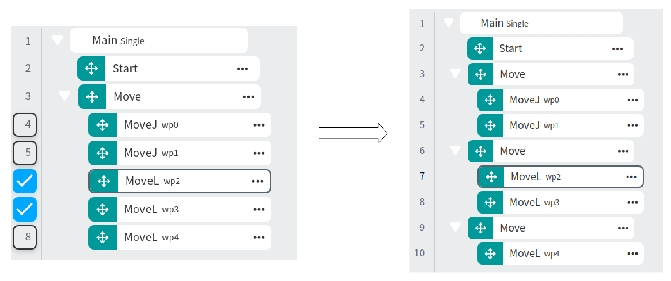
Create Group: Create the selected function blocks as a group: if all the selected blocks are move blocks, a new Move block will be created, and the parameters are the same as the original Move block; Otherwise a Group block will be created
Delete: This function block can be deleted.
Select the start line of this behavior: Click to select this function block as the start line of operation, at this time there will be an icon  in front of the function block and the program will be executed from the function block down. Click the ‘Uncheck Row’ button on the upper right to cancel the setting of the starting row.
In the program editing process, the user can at any time through the upper left side of the page  and
and  Icon to undo or restore changes. Note: Undo changes can be undone up to 10 times.
Once the program tree has changed, the name of the current program will be displayed after the *, indicating that the program has changed, at this time the user can go through the upper left side of the page  icon saves the program to the controller.
Function Block and Parameter Configuration#
The function block list area shows the currently available graphical programming function blocks, which are packaged according to the scenarios commonly used in robot programming. The function blocks provided by this system and their configuration parameters are as follows.
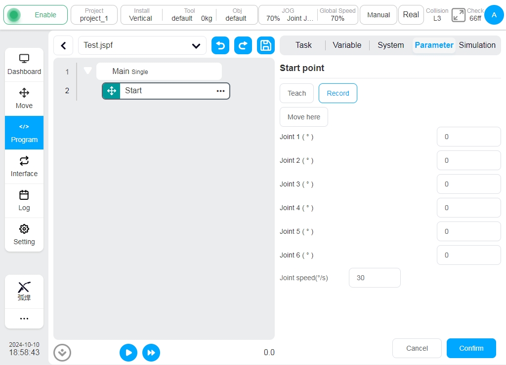
Start Function Block#
The initial robot joints position of the program. If a program starts with an enabled Start function block, a verification between current robot joints position and the initial robot joints position of the program would take effect after start running the program. Otherwise, the program would automatically start running if the Start function block is disabled.
It is always highly recommended that every main program starting with a enabled Start function block. The program run as a subprogram is permitted to disable the Start function block in some cases.
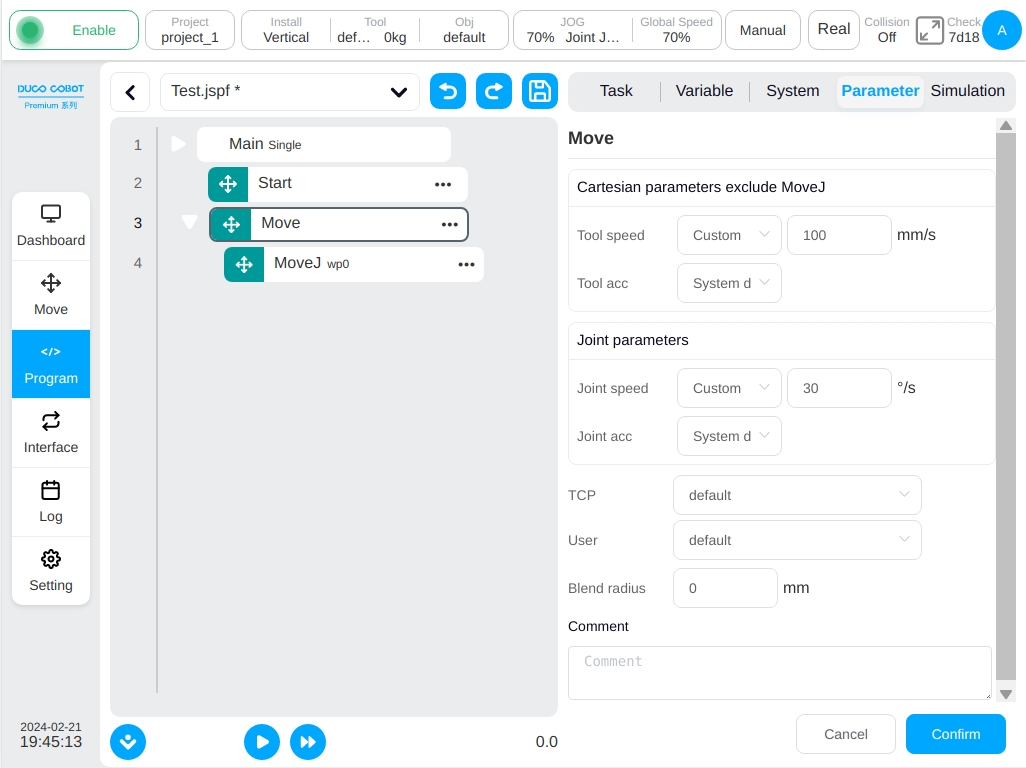
Move Function Block#
When dragging function blocks such as MoveJ, MoveL, etc., if there is no Move node, a Move function block will be automatically created, which contains the following parameters:
End Speed: Unit mm/s, The value range is [0.01, 5000].
End Acceleration: Unit mm/s^2, The value range is [0.01, Infinity].
Joint Angular Velocity: Unit °/s, The value range is [0.01, 225].
Joint Angular Acceleration: Unit °/s^2, The value range is [0.01, Infinity].
Blend Radius: Unit mm, The value ranges from 0 to Infinity.
Reference Coordinate System: tool coordinate system, workpiece coordinate system, can be manually changed.
Among them, the end speed, end acceleration, joint angular velocity and joint angular acceleration can be used to customize the way of directly inputting the values or selecting the variables while the end acceleration and joint angular acceleration can also be selected as the system default. When the end acceleration or joint angular acceleration is selected as the system default, the motion planning will use the optimal planning calculated by the algorithm. Note: The unit of the corresponding parameter will be displayed only when ‘Customize’ is selected; when selecting variables, only specific types of variables can be selected, end speed can only be selected as pose_speed type variable, end acceleration can only be selected as pose_acc type variable, joint angular velocity can only be selected as joint_speed type variable and joint angular acceleration can only be selected as system default type variable, variable and joint angular acceleration can only be selected as joint_acc type variable.
When generating the Move function block, by default, it will get whether all the parent nodes of Move have set the reference coordinate system, if not, it will use the current coordinate system set by the system. For example, the conveyor function block has a set reference coordinate system, i.e. the calibrated conveyor coordinate system, so when dragging the Move class function block to the conveyor child node, the generated Move function block will use the conveyor coordinate system by default.
The Cartesian space motion parameters set by Move block are only applicable to MoveL, MoveC, MoveTCP, MoveWobj, MoveSpiral function blocks and have no effect on other sub-function blocks. The set joint motion parameters are only for MoveJ function block and have no influence on other sub-function blocks.
The reference coordinate system set by the Move function block applies only to the MoveJ, MoveL, MoveC, MoveTCP, MoveWobj and MoveSpiral function blocks, and has no impact on other function blocks.
Specific functional blocks that control robot motion are of the following types:
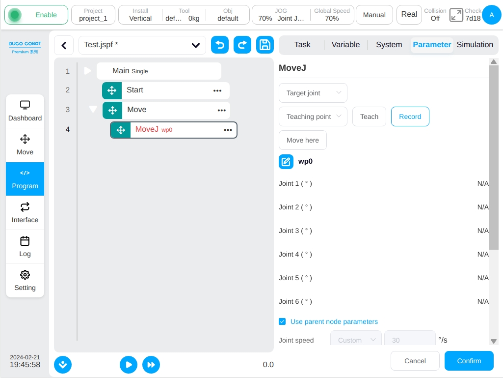
MoveJ
The robot moves in the manner of joint motion and can choose to move to the target joint or the target posture. Parameters available:
Target Joints: Use robot joints position as the target motion position. The target joints position can be decided by directly teaching or using Joints type variable. It can be modified manually after directly teaching the target joints position.
Target Pose: Use robot end-effector pose as the target motion position. The target pose position can be decided by directly teaching or using Pose type variable. It can be modified manually after directly teaching the target end-effector pose.
Teach: Teach the target robot motion position. After clicking the teach button, the ui page would trans to the Move page automatically. After jog and move the robot to the target position, then click the “Record Pose” button. The ui page would trans to the Program page and the target robot position is already recorded.
Record: Record the current robot position as the target robot motion position for current function block.
Move to here: Move the robot to the latest recorded robot target motion position. After clicking the button, the 3D simulation model would automatically shows. Holding the “Move” button at the buttom of the 3D simulation model would control the robot moving to the recorded target robot motion position.
Note
Attention: Using target pose as the robot target motion position of the function block and then moving robot to the target position by “Move to here”, the final robot joints position would be different with the same robot end-effector pose if the start position of movement is different. It is able to verify whether the final robot joints position same as the one recorded during teaching through 3D simulation model and its shadow model.
Note
Attention: Using target pose as the robot target position of the function block, if the kinematic solution of the current robot joints position during program running is different from the one of the recorded target robot joint position, an error would raise to notify this abnormal condition.
Use Parent Node Coordinate System: This parameter can be set when the target position posture is selected. If this parameter is selected, the function block uses the reference coordinate system set by the parent node Move function block.
Reference Coordinate System: This can be set when the target position posture is selected. If the parent coordinate system is not checked, its reference coordinate system can be set separately for the function block.
Use Parent Node Parameters: When selected, the function block uses the joint angular velocity and joint angular acceleration parameters set by the parent node Move function block. If this parameter is not selected, the user need to set the joint angular velocity and joint angular acceleration for this function block. This parameter is selected by default.
Joint Angular Velocity: Unit °/s, the user can customize the value or select a variable, the value range is [0.01, 225].
Joint Angular Acceleration: Unit °/s2, the user can customize the value or select a variable, the value range is [0.01, Infinity].
Parent Node Blend Radius: If this parameter is selected, the blend radius parameter set by the parent node Move function block is used. If this parameter is not selected, you need to set the blend radius for this function block. This parameter is selected by default.
Blend Radius: The unit mm, the value range is [0, Infinity],0 indicates no blend.
Note
Attention: Blend radius with improper value would lead to vibration during blend motion. It is recommended to adjust the blend radius value according to the specific cases.
Note
Attention: The blend radius with minor value may lead to a failure of blend motion. In these cases, it is recommended that using the MotionConfig function block to adjust the “Blend Preload” to the “Motion start point” option if no logic problem occured. If it still has a failure for the blend motion, decreasing the motion speed or adjusting the target point to ensure the origin motion period time of the function block not less than 100ms is a feasible method to make the blend motion successful.
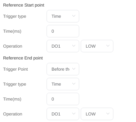
Enable OP: The OP feature allows user to set generic digital outlet states or set the tool output state or manipulate custom events during track execution.
If OP is enabled, the user need to perform the following configurations:
It can be triggered after the start of the trajectory and before/after the end of the trajectory.
Trigger Type: The user can select no trigger, time trigger, distance trigger.
Trigger Delay: Set time (Unit: ms)
Trigger Action: Select a port and port status or perform a custom event.
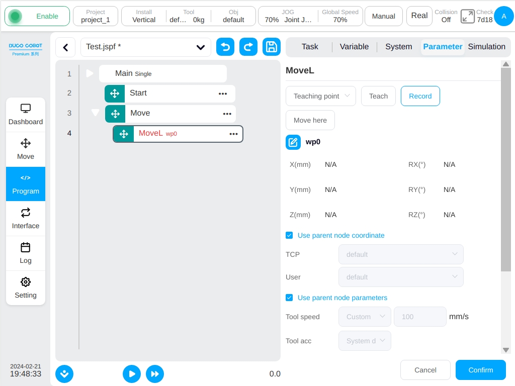
MoveL
The robot moves to the target posture in a straight line. Parameters can be set:
Target Pose: It can be set by teaching or set as a variable and can be changed manually after teaching setting.
Teach: Teach the target robot motion position. After clicking the teach button, the ui page would trans to the Move page automatically. After jog and move the robot to the target position, then click the “Record Pose” button. The ui page would trans to the Program page and the target robot position is already recorded.
Record: Record the current robot position as the target robot motion position for current function block.
Move to here: Move the robot to the latest recorded robot target motion position. After clicking the button, the 3D simulation model would automatically shows. Holding the “Move” button at the buttom of the 3D simulation model would control the robot moving to the recorded target robot motion position.
Note
Attention: Moving robot to the target position by “Move to here”, the final robot joints position would be different with the same robot end-effector pose if the start position of movement is different. It is able to verify whether the final robot joints position same as the one recorded during teaching through 3D simulation model and its shadow model.
Note
Attention: If the kinematic solution of the current robot joints position during program running is different from the one of the recorded target robot joint position, an error would raise to notify this abnormal condition.
Parent Coordinate System: If this parameter is selected, the function block uses the reference coordinate system set by the parent Move function block. This parameter is selected by default.
Reference Coordinate System: If the parent coordinate system is not selected, the reference coordinate system can be set separately for the function block.
Use Parent Node Parameters: When checked, the function block uses the end speed and end acceleration parameters set by the parent node Move function block. If the user do not select this option it needs a setting of the end speed and end acceleration for this function block. They are selected by default
Tool Speed: Unit mm/s, the user can customize the value or select a variable, the value range is [0.01, 5000].
Tool Acceleration: Unit mm/s2, the user can customize the value or select a variable, the value range is [0.01, Infinity].
Parent Node Blend Radius: If this parameter is selected, the blend radius parameter set by the parent node Move function block is used. If this parameter is not selected, the user need to set the blend radius for this function block. This parameter is selected by default.
Blend Radius: Unit mm, the value range is [0, Infinity], 0 indicates no blend.
Note
Attention: Blend radius with improper value would lead to vibration during blend motion. It is recommended to adjust the blend radius value according to the specific cases.
Note
Attention: The blend radius with minor value may lead to a failure of blend motion. In these cases, it is recommended that using the MotionConfig function block to adjust the “Blend Preload” to the “Motion start point” option if no logic problem occured. If it still has a failure for the blend motion, decreasing the motion speed or adjusting the target point to ensure the origin motion period time of the function block not less than 100ms is a feasible method to make the blend motion successful.
Enable OP: The OP feature allows the user to set generic digital outlet states or set the tool output state or manipulate custom events during track execution.
If OP is enabled, the user need to perform the following configurations:
It can be triggered after the start of the trajectory and before/after the end of the trajectory.
Trigger Type: The user can select no trigger, time trigger, distance trigger.
Trigger Delay: Set time (Unit: ms)
Trigger Distance: Set the distance (Unit: mm)
Trigger Action: Select a port and port status, or perform a custom event.

OP Operation in Blend:
The robot sets the general digital output state during the trajectory execution. When used with blends, the three moveL blends, for example, have the following effect:
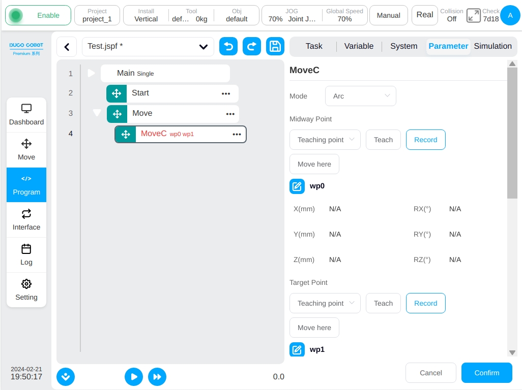
MoveC
Robot moves according to arc or whole circle, parameters can be set:
Mode: Arc or full circle
Intermediate point posture/intermediate point 1: It can be set by teaching or set as a variable and can be changed manually after teaching setting.
Target pose/middle point 2: It can be set by teaching or as a variable, and can be changed manually after teaching setting.
Teach: Teach the target robot motion position. After clicking the teach button, the ui page would trans to the Move page automatically. After jog and move the robot to the target position, then click the “Record Pose” button. The ui page would trans to the Program page and the target robot position is already recorded.
Record: Record the current robot position as the target robot motion position for current function block.
Move to here: Move the robot to the latest recorded robot target motion position. After clicking the button, the 3D simulation model would automatically shows. Holding the “Move” button at the buttom of the 3D simulation model would control the robot moving to the recorded target robot motion position.
Note
Attention: Moving robot to the target position by “Move to here”, the final robot joints position would be different with the same robot end-effector pose if the start position of movement is different. It is able to verify whether the final robot joints position same as the one recorded during teaching through 3D simulation model and its shadow model.
Note
Attention: If the kinematic solution of the current robot joints position during program running is different from the one of the recorded target robot joint position, an error would raise to notify this abnormal condition.
Parent coordinate system: If this parameter is selected, the function block uses the reference coordinate system set by the parent Move function block. This parameter is selected by default.
Reference coordinate system: If the parent coordinate system is not selected, the reference coordinate system can be set separately for the function block.
Use parent node parameters: When checked, the function block uses the end speed and end acceleration parameters set by the parent node Move function block. If the user do not select this option, it needs a setting of the end speed and end acceleration for this function block. They are selected by default.
Tool speed: Unit mm/s, the user can customize the value or select a variable, the value range is [0.01, 5000].
Tool acceleration: Unit mm/s^2, the user can customize the value or select a variable, the value range is [0.01, Infinity].
Parent node Blend radius: If this parameter is selected, the blend radius parameter set by the parent node Move function block is used. If this parameter is not selected, you need to set the blend radius for this function block. This parameter is selected by default.
Blend radius: Unit mm, the value range is [0, Infinity], 0 indicates no blend.
Note
Attention: Blend radius with improper value would lead to vibration during blend motion. It is recommended to adjust the blend radius value according to the specific cases.
Note
Attention: The blend radius with minor value may lead to a failure of blend motion. In these cases, it is recommended that using the MotionConfig function block to adjust the “Blend Preload” to the “Motion start point” option if no logic problem occured. If it still has a failure for the blend motion, decreasing the motion speed or adjusting the target point to ensure the origin motion period time of the function block not less than 100ms is a feasible method to make the blend motion successful.
Posture control mode: If ‘Consistent with the End Point’ is selected, the robot’s posture plans the posture in the arc path according to the end point posture; If ‘Consistent with the Starting Point’ is selected, the robot’s posture in the arc path is planned according to the starting point’s posture and the posture in the path process is consistent with the starting point. If ‘Constrained by the Center of the Circle’ is selected, the posture of the robot is constrained relative to the posture change generated by the arc motion.
Enable OP: The OP feature allows the user to set generic digital outlet states or set the tool output state or manipulate custom events during track execution.
The OP parameter configuration is the same as MoveL.
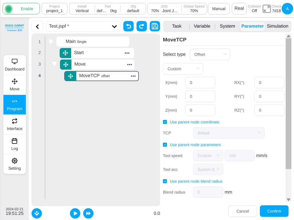
MoveTCP
The robot moves along the tool coordinate system.
The user can enter offsets directly in each direction, or use variables. Two points can be taught and the offset between the two points is used as the offset value of the move. Other configurable parameters:
Parent coordinate system: If this parameter is selected, the function block uses the reference coordinate system set by the parent Move function block. This parameter is selected by default.
Reference coordinate system: If the parent coordinate system is not selected, the reference coordinate system can be set for the function block separately. If the user choose to set incremental mode, just select the tool coordinate system; If you choose to set two points, you need to set the tool coordinate system and the workpiece coordinate system.
Use parent node parameters: When checked, the function block uses the end speed and end acceleration parameters set by the parent node Move function block. If the user do not select this option it needs a setting of the end speed and end acceleration for this function block. They are selected by default.
Tool speed: Unit mm/s, the user can customize the value or select a variable, the value range is [0.01, 5000].
Tool acceleration: Unit mm/s^2, the user can customize the value or select a variable, the value range is [0.01, Infinity].
Parent node Blend radius: If this parameter is selected, the blend radius parameter set by the parent node Move function block is used. If this parameter is not selected, the user need to set the blend radius for this function block. This parameter is selected by default.
Blend radius: Unit mm, the value range is [0, Infinity], 0 indicates no blend.
Note
Attention: Blend radius with improper value would lead to vibration during blend motion. It is recommended to adjust the blend radius value according to the specific cases.
Note
Attention: The blend radius with minor value may lead to a failure of blend motion. In these cases, it is recommended that using the MotionConfig function block to adjust the “Blend Preload” to the “Motion start point” option if no logic problem occured. If it still has a failure for the blend motion, decreasing the motion speed or adjusting the target point to ensure the origin motion period time of the function block not less than 100ms is a feasible method to make the blend motion successful.
Enable OP: The OP feature allows user to set generic digital outlet states or set the tool output state or manipulate custom events during track execution.
The OP parameter configuration is the same as MoveL.
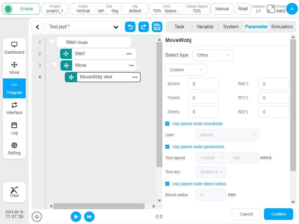
MoveWobj
Control the robot tool moving foward a incremental distance along the workpiece coordinate system.
The user can enter offsets directly in each direction, or use variables. Two points can be taught and the offset between the two points is used as the offset value of the move. Other configurable parameters:
Parent coordinate system: If this parameter is selected, the function block uses the reference coordinate system set by the parent Move function block. This parameter is selected by default.
Reference coordinate system: If the parent coordinate system is not selected, the reference coordinate system can be set for the function block separately. If the user choose to set incremental mode, just select the workpiece coordinate system; If you choose to set two points, you need to set the tool coordinate system and the workpiece coordinate system of the teach points.
Use parent node parameters: When checked, the function block uses the end speed and end acceleration parameters set by the parent node Move function block. If the user do not select this option it needs a setting of the end speed and end acceleration for this function block. They are selected by default.
Tool speed: Unit mm/s, the user can customize the value or select a variable, the value range is [0.01, 5000].
Tool acceleration: Unit mm/s^2, the user can customize the value or select a variable, the value range is [0.01, Infinity].
Parent node Blend radius: If this parameter is selected, the blend radius parameter set by the parent node Move function block is used. If this parameter is not selected, the user need to set the blend radius for this function block. This parameter is selected by default.
Blend radius: Unit mm, the value range is [0, Infinity], 0 indicates no blend.
Note
Attention: Blend radius with improper value would lead to vibration during blend motion. It is recommended to adjust the blend radius value according to the specific cases.
Note
Attention: The blend radius with minor value may lead to a failure of blend motion. In these cases, it is recommended that using the MotionConfig function block to adjust the “Blend Preload” to the “Motion start point” option if no logic problem occured. If it still has a failure for the blend motion, decreasing the motion speed or adjusting the target point to ensure the origin motion period time of the function block not less than 100ms is a feasible method to make the blend motion successful.
Enable OP: The OP feature allows user to set generic digital outlet states or set the tool output state or manipulate custom events during track execution.
The OP parameter configuration is the same as MoveL.
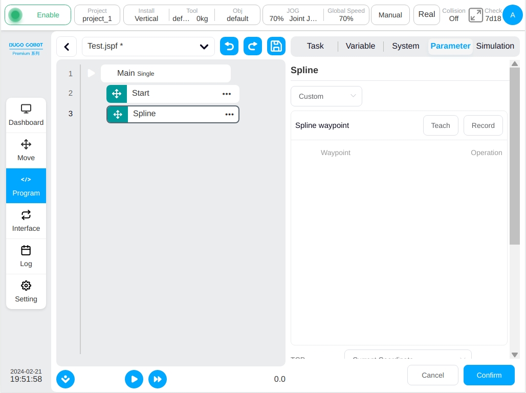
Spline
The end of the robot is controlled to move according to the spline curve. The user can choose Customize or direct teaching point, or select variables. When selecting variables, it can only be selected pose_list variables. Other parameters can be set:
Spline waypoints: Add, edit, and delete waypoints to generate splines based on the waypoints
Reference coordinate system: When teaching point position is shown, the default is the current tool and workpiece coordinate system, which can be manually changed
Tool speed: Unit mm/s, the user can customize the value or select a variable, the value range is [0.01, 5000].
Tool acceleration: Unit mm/s2, the user can customize the value or select a variable, the value range is [0.01, Infinity].
Blend radius: Unit mm. the value range is [0, Infinity], 0 indicates no blend.
Enable OP: The OP feature allows user to set generic digital outlet states or set the tool output state or manipulate custom events during track execution.
The OP parameter configuration is the same as MoveL
Note
When two splines are used together, the end point of the former spline cannot be the same as the start point of the latter spline.
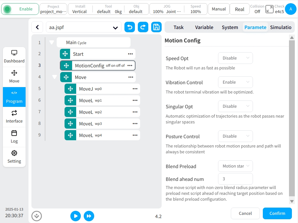
MotionConfig
Turn on or off sports-related configurations. Optional configuration:
Speed optimization: After speed optimization is turned on, the robot will execute the motion command at the highest possible speed under the premise of meeting the system constraints.
Vibration control: When the vibration control is turned on, it is optimized for the vibration of the end of robot.
Singularity avoidance: After singularity avoidance is turned on, the trajectory of the robot will be automatically optimized when it passes near the singular space.
Note
When the singularity avoidance function is enabled, if you pass through a singularity, the original set path will be affected, and the speed of individual joints will become faster, which may cause the robotic arm to report an error due to joint overspeed.
Posture constraint: After the posture constraint is opened, the robot motion attitude will always be consistent with the relationship between the path.
Blend preload: The user can select the motion middle point or the motion start point. A motion script with the blend radius configured prereads subsequent scripts to the blend radius based on this parameter.
Note
For the blend of short line segments and long line segments, it is usually necessary to set the blend preload position of the short line segment as the motion starting point to ensure that the program has enough time for the blend trajectory planning. However, this does not mean that it is possible to perform short-line blend of long segments after setting the starting point of the movement as the blend preload point.
Blend preload num:Only when the blend preload point is set to be the motion start point, it is feasible to further define the number of move scripts which be preloaded. It is able to preload as maximum as three move scripts for current version. It is highly recommended to use this function to preload as much move scripts as possible to ensure the stability of blend move when the application requires robots to move along short path continuously under high motion speed.
Note
When it is set to preload multiple move scripts and there has other types of function blocks such as IO RW, register RW, variables rw, interface operation and etc, these function blocks will be executed ahead of the robot motion to the target teach points. So it is necessary to verify the complete correctness of IO operation, register value, variable value and program logic before automatically running program.
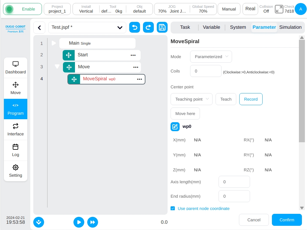
MoveSpiral
Robot does spiral trajectory movement, parameters can be set:
Spiral teaching mode: Parameter setting or end point setting.
Total number of turns: The total number of turns of the robot, positive number is clockwise rotation, negative number is counterclockwise rotation.
Helix center point: This can be set by teaching or set as a variable, can be manually changed after teaching setting.
Axial moving distance: When the teaching mode is set to parameter setting, the parameter must be set. The positive and negative signs follow the right hand rule (unit: mm).
End point radius: This parameter is required when the teaching mode is set to parameter setting. The unit is mm.
End point of track: When the teaching mode is set to end point, it can be set by teaching mode, or set to variable, which can be manually changed after teaching setting.
Parent coordinate system: If this parameter is selected, the function block uses the reference coordinate system set by the parent Move function block. This parameter is selected by default.
Reference coordinate system: If the parent coordinate system is not selected, the reference coordinate system can be set separately for the function block.
Use parent node parameters: When checked, the function block uses the end speed and end acceleration parameters set by the parent node Move function block. If you do not select this option, you need to set the end speed and end acceleration for this function block. They are selected by default.
Tool speed: Unit mm/s, the user can customize the value or select a variable, the value range is [0.01, 5000].
Tool acceleration: Unit mm/s^2, the user can customize the value or select a variable, the value range is [0.01, Infinity].
Enable OP: The OP feature allows user to set generic digital outlet states or set the tool output state or manipulate custom events during track execution.
The OP parameter configuration is the same as MoveL.
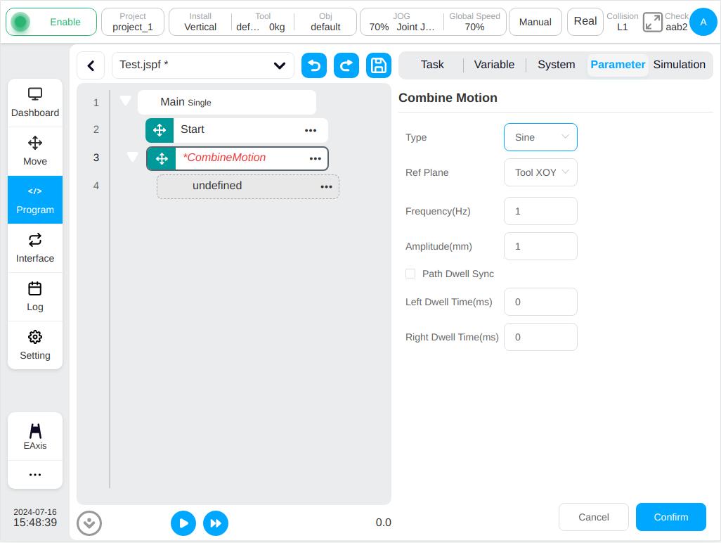
CombineMotion
Only for the linear and circular motion control robot to do compound trajectory motion, parameters can be set:
Trajectory type: The default is triangle, optional triangle, sine, arc, trapezoid, 8.
Reference plane: The default is tool XOY, optional tool XOY or tool XOZ or tool YOZ or user XOY or user XOZ or user YOZ.
Path dwell sync: When the trajectory type is sine or trapezoid, the parameter that need to be configured is not checked by default. When this parameter is checked, the main path of the robot movement can be stopped at the same time during the left and right stays.
Frequency: The default value is 1 (Unit: Hz)
Amplitude: The default value is 1 (Unit :mm)
Left residence time: specifies the parameter to be configured when the trajectory type is sine or trapezoid (Unit: ms)
Right residence time: specifies the parameter to be configured when the trajectory type is sine or trapezoid (Unit: ms)
Basic Function Block#
Set
Set function block. The digital output port of the control cabinet and the digital output port at the end of the robot can be set as high level electronics or low level electronics or pulse signal. When set as pulse signal, the frequency and duty cycle of the pulse need to be set; Assign a value to a program or system variable.
Note
When you assign a variable, the expression keyboard will pop up. Please fill in the assignment according to the expression syntax. If you assign “Hello” to a string variable, enter “Hello”on the keyboard (double quotes cannot be omitted).

Wait
Wait function block. The user can choose to wait for a period of time, wait for DI signal, wait for the end of a certain thread or expression, the program execution to this function block will wait until the set conditions are met.
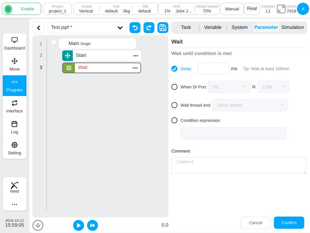
Note
Note: The delay is set to at least 100ms!
When an option other than “Delay” is selected, a checkbox is displayed indicating whether to enable timeout detection. If you select “Enable Timeout Detection”, you can input timeout period and timeout variables, as shown in the following figure.
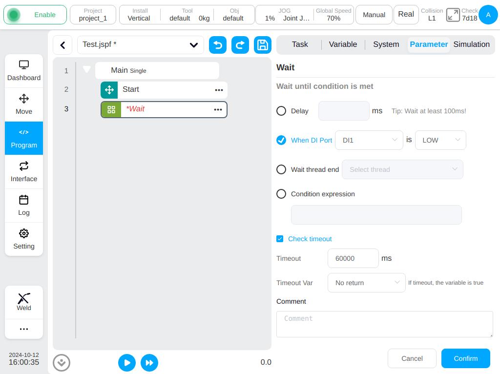
The user can manually input the timeout period, the default timeout time is 60000ms; and the user can also use the timeout variable to determine whether the timeout is timeout, but the timeout variable is optional and it can not be selected.
When the waiting condition is not met and the timeout is overed, a timeout signal will be output, and if the robot is in automatic mode, it will continue to wait until the condition is met; If the robot is in manual mode, the program will be suspended after the timeout and a pop-up window will appear as shown below.
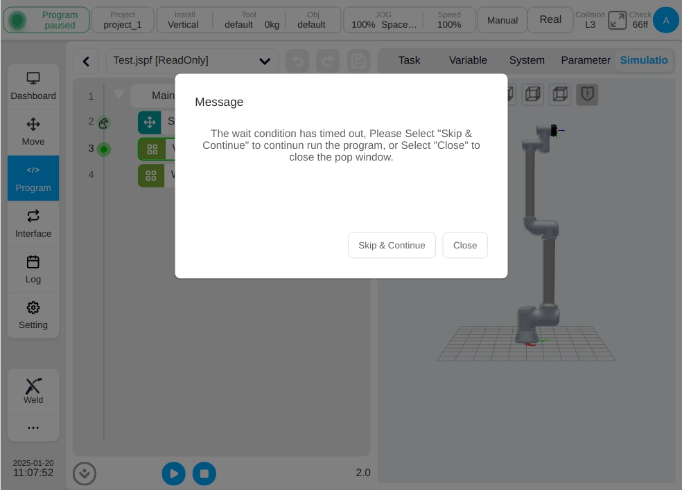
When the user selects “Skip & Continue”, the program skips Wait and continues to run the program; When the user selects “Close”, the program continues to pause and the pop-up window is closed.
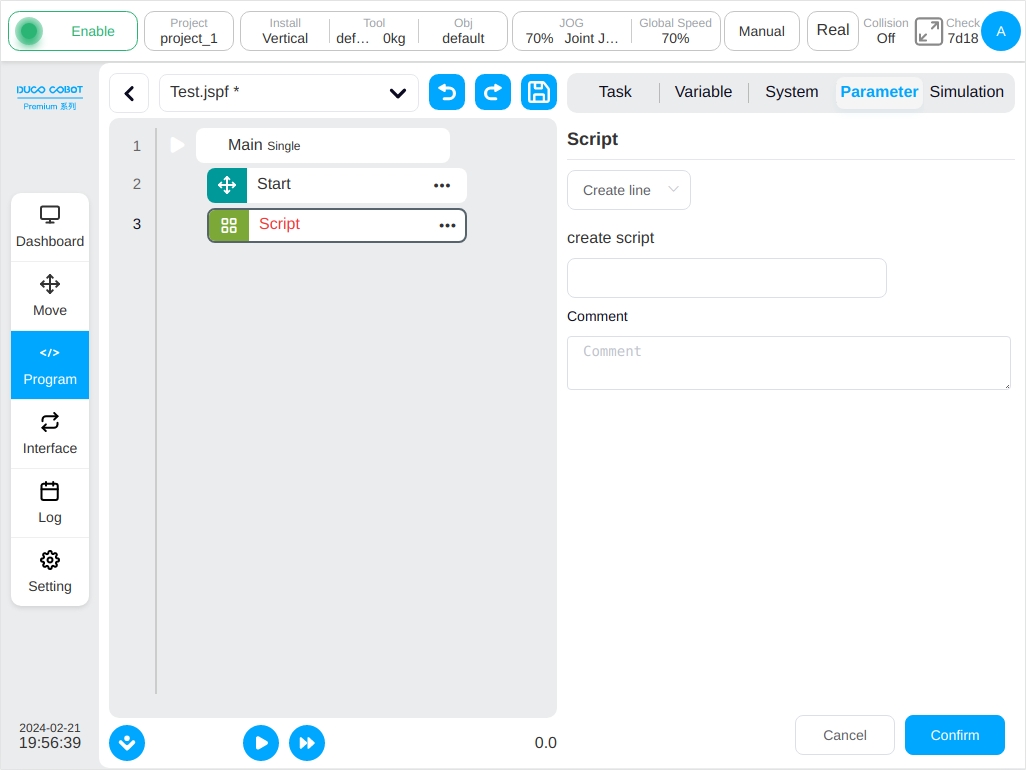
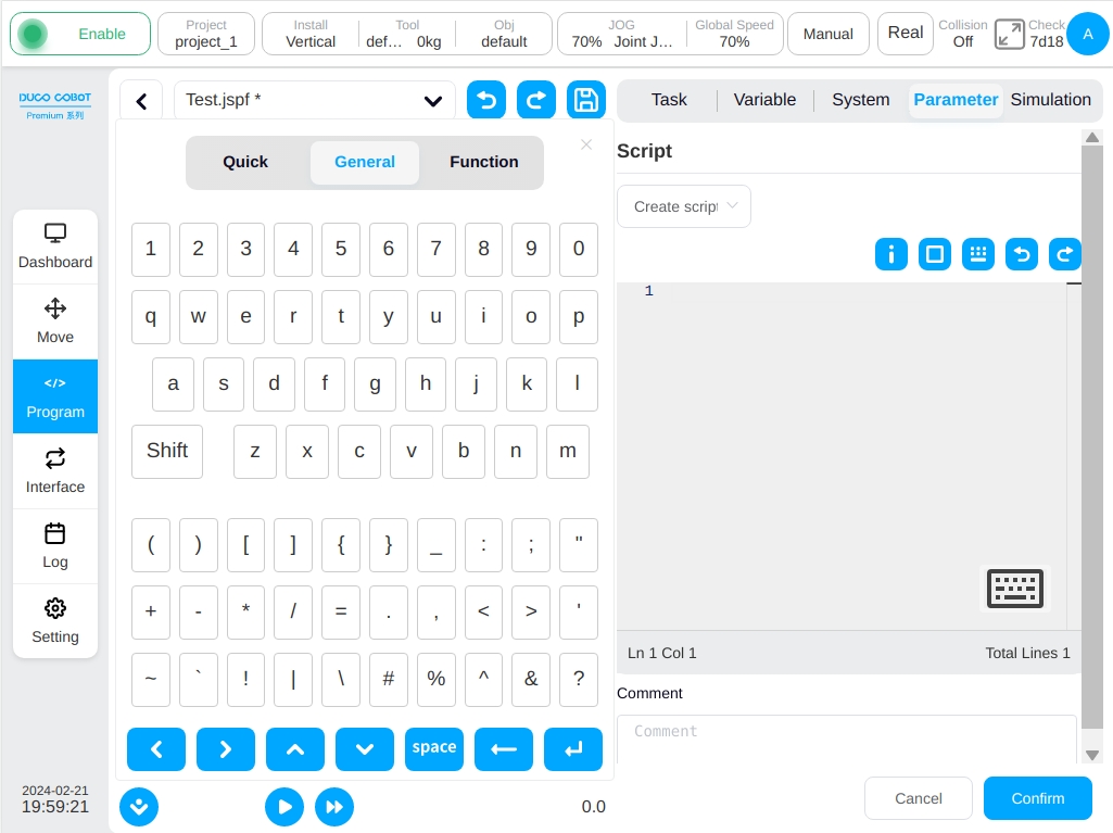
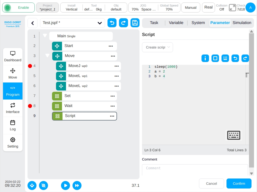
Script
Script function block. The user can choose expressions, scripts or script files. Expressions can be used to create a line of script using the Expression Editor, see Section 8 Input Keyboard (Expression Input Keyboard) for expression input; Scripts can be used to write an entire section of script code; Script Files can be selected from the files to script a script file. See the Scripting Manual for a description of the script code.
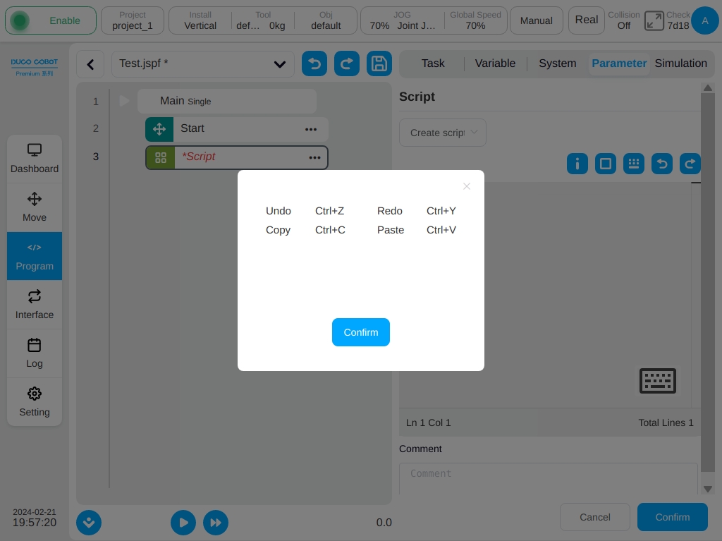
When selecting a script to write the entire piece of code, click above the edit area  icon will pop up a shortcut key prompt box, as shown below.
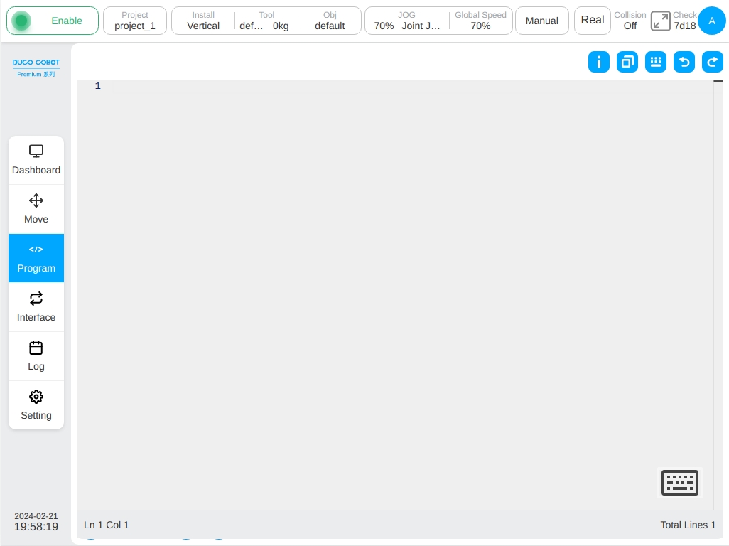
Click the maximization icon  above the edit area will be displayed in the script editing area as follows. Click on the top right of the maximization interface
  restore the icon to the original interface size. is undo the icon, is the recovery icon. The number of lines and columns where the cursor is located is displayed in the lower left corner of the editing area, and the total number of script lines is displayed in the lower right corner.
In script writing mode, the user can use the built-in shortcut box and external keyboard for input. Click The icon  above the scripting area pops up the system shortcut input box, which is suspended above the editor as shown below and can be held down and dragged.
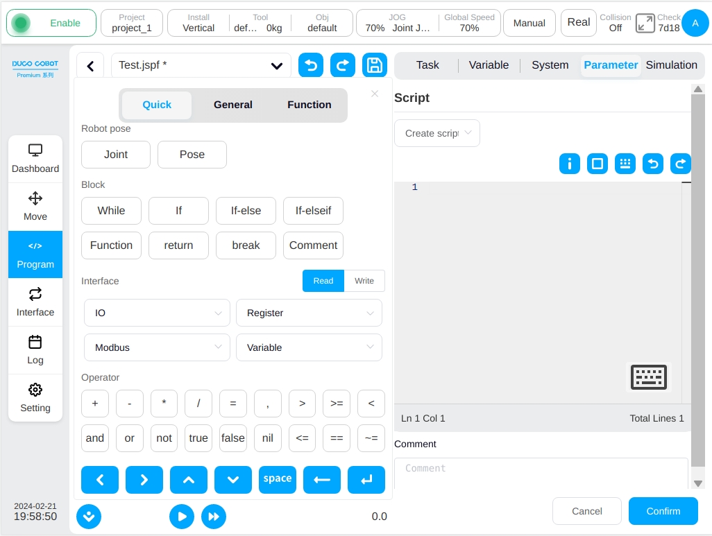
Shortcut input box contains three labels, which are shortcut input, general keyboard and script functions. Below the input box for some commonly used control keys, the functions are cursor left, cursor right, cursor up, cursor down, enter space, delete and line feed.

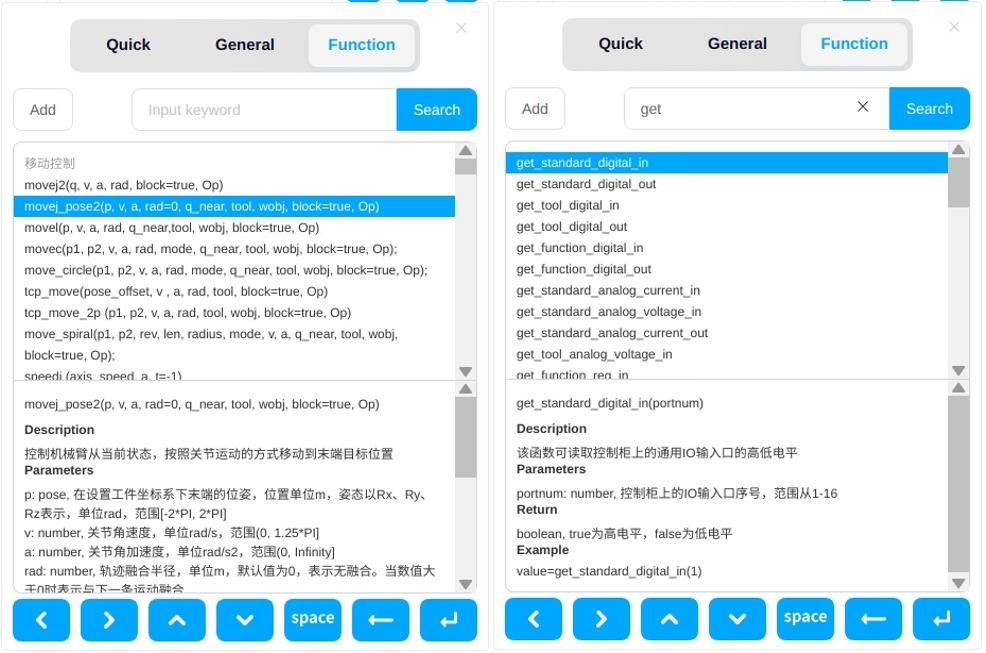
Shortcut input provides shortcuts for some commonly used functions. The main functions are
Point Position: Click the ‘Joint’ button to enter the joint value of the current robot unit in rad; Click the ‘Pose’ button to enter the position and posture of the current robot tool on the set workpiece unit in rad.
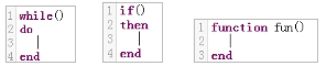
Function: The user can enter While loops, conditional branches, function definitions, single-line comments, etc.
IO/Register/Modbus/Variable: The user can choose to read or write through this function, the system will automatically convert to the corresponding script function. If the user select Read function and select DI1, the system automatically enters the corresponding script function get_standard_digital_in(1).
Operator: Enter some commonly used operators.
The general keyboard is similar to a physical keyboard and allows the uesr to enter upper and lower case letters, numbers and symbols.
Script function can be selected from the list of script functions. After selected, in the lower part of the script function will show the description and examples, with double-click or click on the upper-left ‘Add’ button can be entered into the script area which support script search.
Log
Log function block. The user can print messages or variable values to a log file.

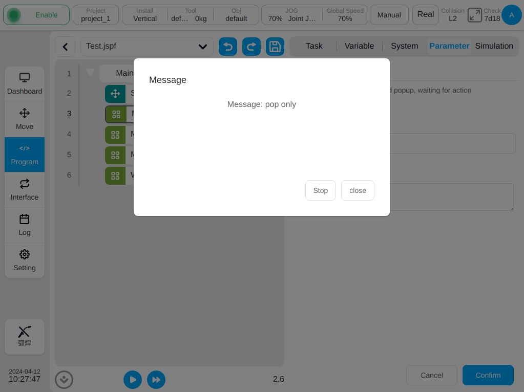
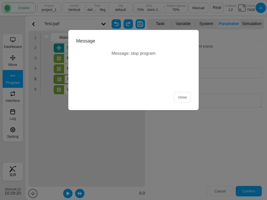
Message
Message pop-up function block. The message pop-up box can be configured to pause the program, pop-up only, or stop the program.
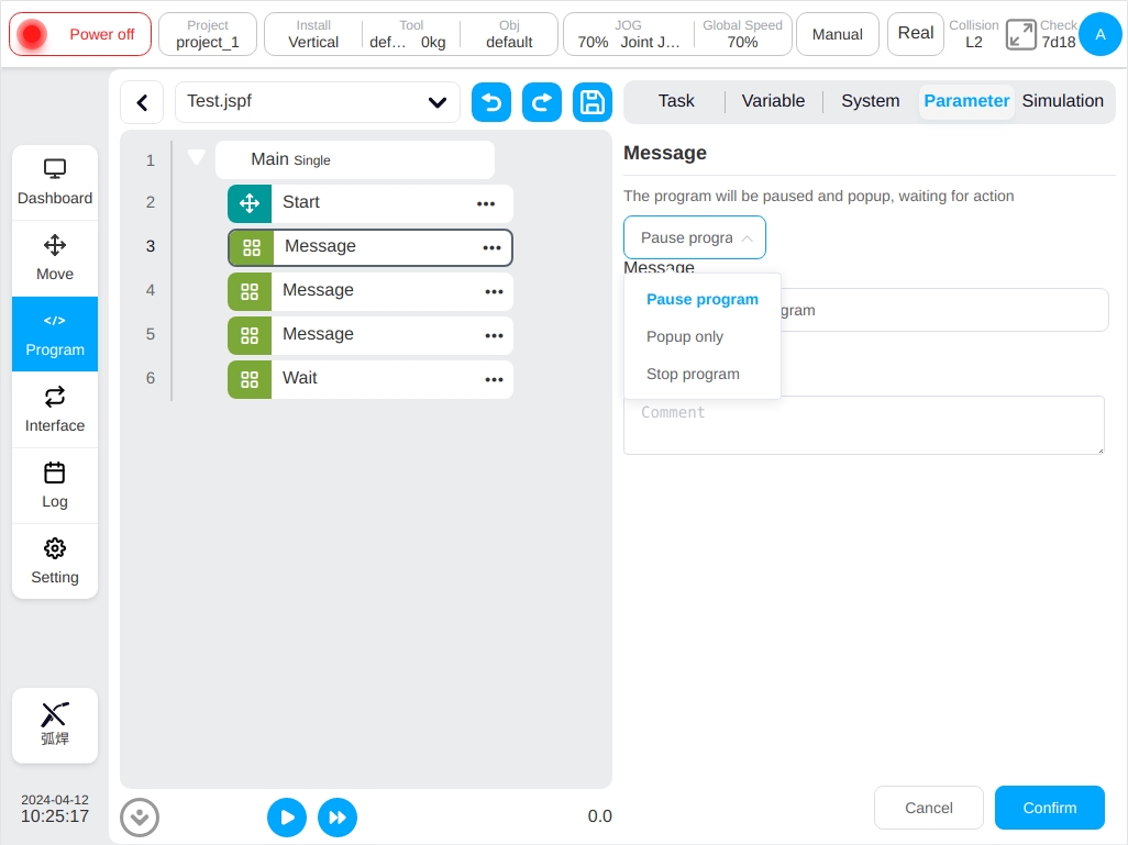
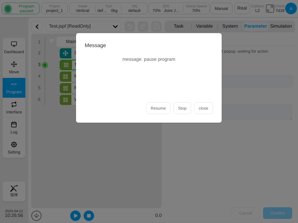
When you choose to pause the program, set a message, and when the program runs to this function block, a dialog box will pop up to display the message and the program will be suspended, and the user can choose to continue running, stop the program, or close the pop-up window.
When you select only pop-up window, set a message and a dialog box will pop up when the program runs to this function block, but the program will continue to run, and the user can choose to stop the program or close the pop-up window.
When you choose to stop the program, set a message, and when the program runs to this function block, a dialog box will pop up to display the message and the program will stop running directly, and the user can choose to close the pop-up window.
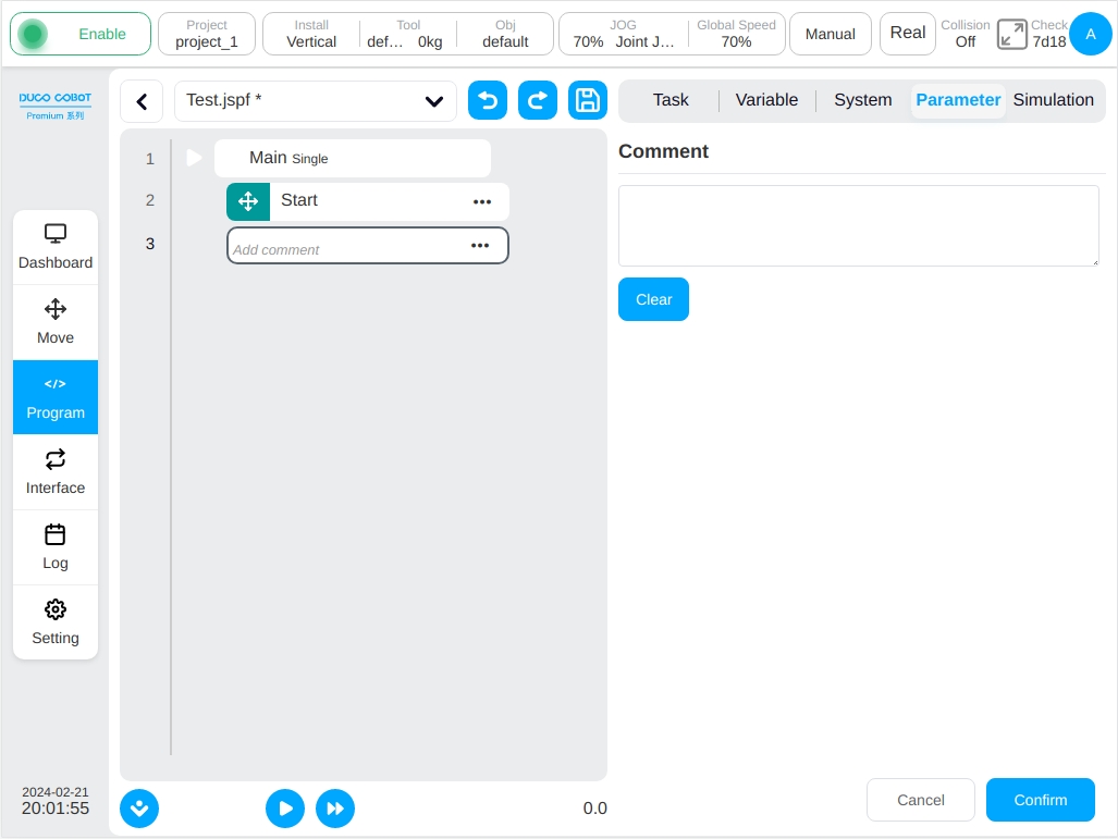
Comment
Comment function block. Adds a comment to the program tree. This function block does not perform any action while the program is running.
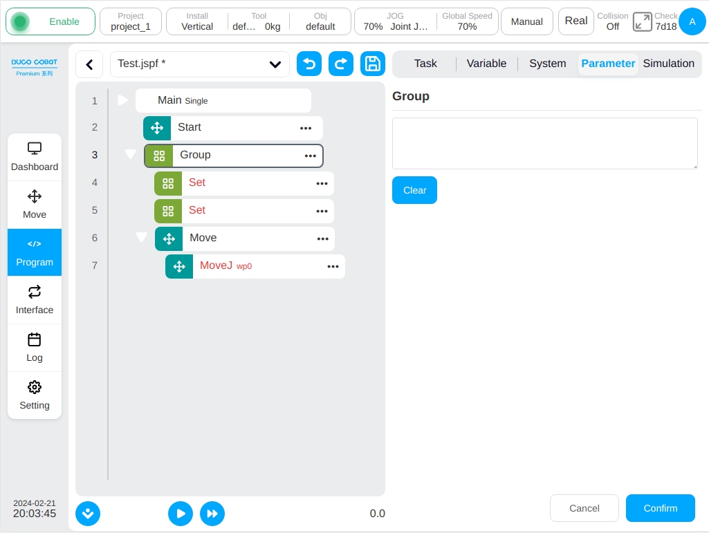
Group
Group functional blocks. It is used to organize the program, and some functional blocks can be placed under a ‘Group’ to facilitate the organization and reading of the program while the program execution is not affected.
CoordOffset
Coordinate offset function block. It is used to set an offset based on the workpiece coordinate system which can be customized or set variables. This offset is added to the reference work coordinate system of the subsequent ‘Move’ categlory function block. When the program is running, the program stops coordinate system offset.
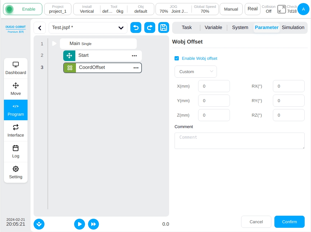
Note
The value of wobj offset set by the CoordOffset function block during running the program would be reset to 0 automatically once the program is finished. During running the program, if the operator pause the program and move the robot manually in cartesian space, the reference wobj coordinate value is the one that be modified by the CoordOffset function block. This modification would only be reset until the program is stopped manually or automatically finished.
SetLoad
Set the fetching load function block. The robot’s current load (mass, center of mass) can be set during program operation.

GetListElement

Gets the list element function block. This function block is used to get one of the elements from a variable of type list and dump the value of that element into the specified variable.
Select the list type: Currently support num_list, pose_list, joints_list, three types of variables. To use it, the user first need to create the desired list class variable.
Index: The position of the desired element in the list, counting from 1. The user can enter an index value directly or obtain an index value from a variable.
Element: Specifies the corresponding variable to which the obtained element needs to be transferred that support number, pose, joints three types of variables. To use it, the user needs to first establish the desired variables.
Note
GetListElement function block does not change the data in the original list variable. It does not delete the obtained element. It copies instead of cutting.
Note
The type of the transferred variable needs to be the same as the type of the element in the list variable. For example, the pose variables obtained from the pose_list variable cannot be stored into the joints variable.
RemoveListElement
Removes the list element function block. This function block is used to delete an element in a variable of the list type from the list type.
Select the list type: Currently support num_list, pose_list,j oints_list, three types of variables. To use it, the user first need to create the desired list class variable.
Index: The position of the desired element in the list, counting from 1. The user can enter an index value directly or obtain an index value from a variable.
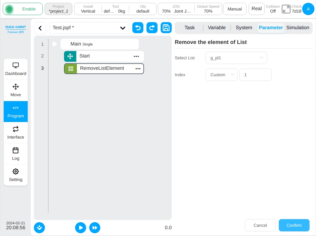
Note
RemoveListElement block changes the data in the original list variable and the position of the element after the index number. For example, pose_list contains the pose variable {A,B,C,D}.When you use the RemoveListElement block and remove the variable B, the element in the new pose_list becomes {A,C,D} instead of {A,nul,C,D}, and null indicates that there is a pose variable, but the value is empty.
TimerStart
Timing start function block. This function block is used to start the timer.

TimerEnd
Timer end function block. This function block is used to end the time of the timer.
Select variables: Only variables of the global timer type are supported. To use it, the user need to create the global timer class variable first.

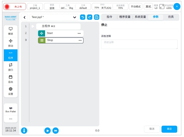
Stop
Stop the function block. This function block is used to issue program stop instructions.
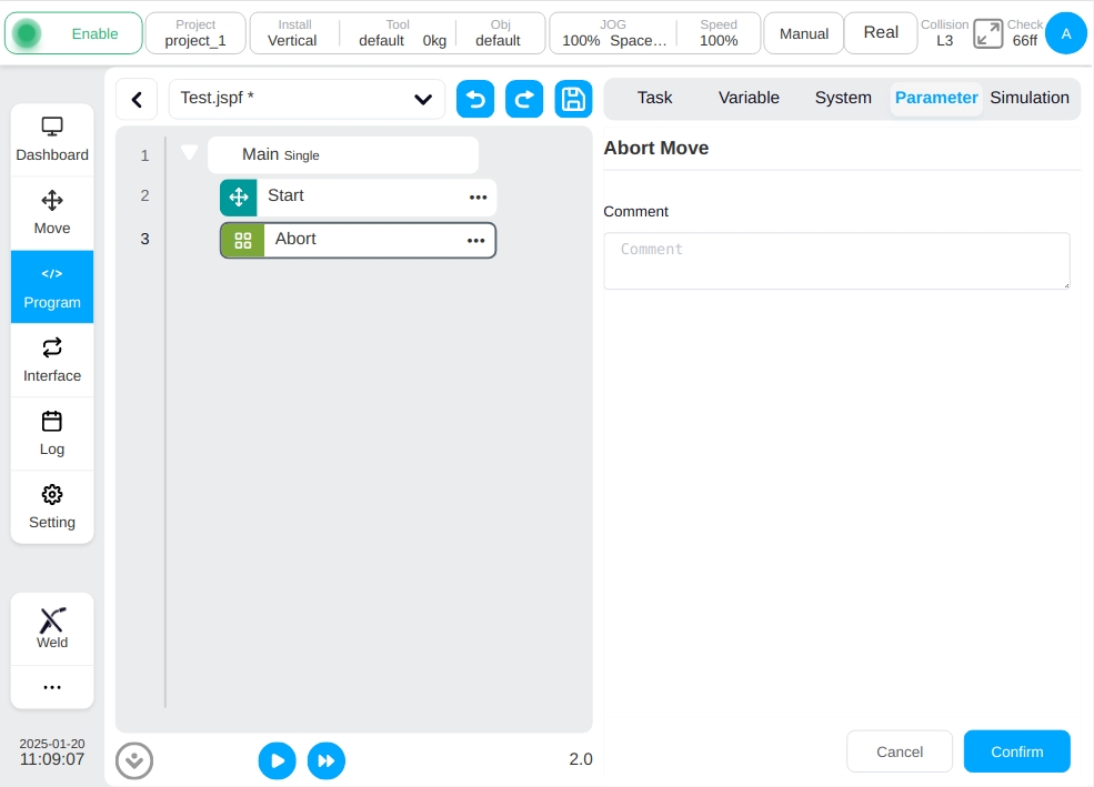
Abort
Abort the motion task function block. This function block is used to issue an abort command for the current motion task.
Flow Control#
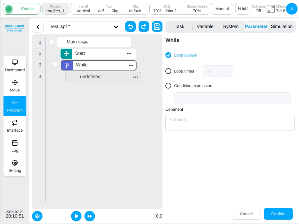
While
Loop function block. A loop executes its internal function blocks. The user can set it to loop all the time; specify the number of loops; Specify a loop condition that will run in a loop as long as the loop condition is true.
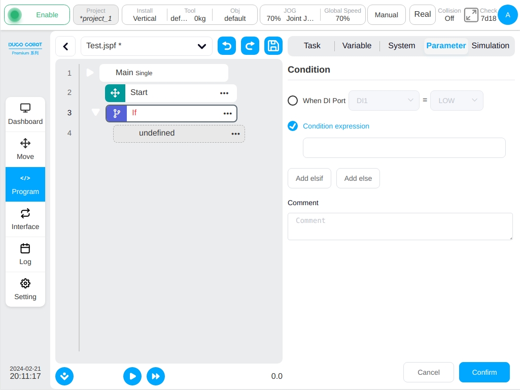
If
Conditional function block. You can set a digital input port condition or a condition expression. If the condition is met, the function block in IF is executed, and subsequent elsif or else function blocks can be added
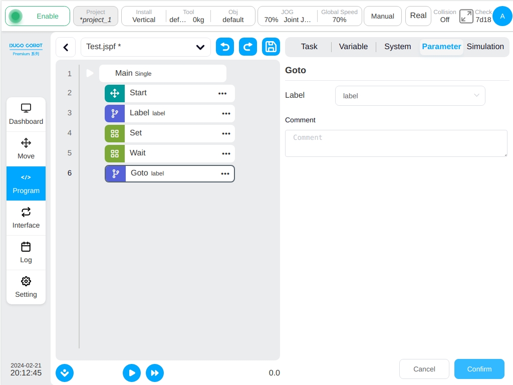
Goto&Label
The Goto function, when used in conjunction with the Label function is able to transfers the control point of the program to the Label position.
Firstly, creating a Label function block, marking the jump point and name the jump point. Using the Goto block, selecting the location to jump to.
The example program as shown in the figure indicates that when the program runs to line 6, it will jump to label1 in line 3 and then execute downward, that is, the Set function block in line 4 and the wait function block in line 5 will run twice.
Communication#
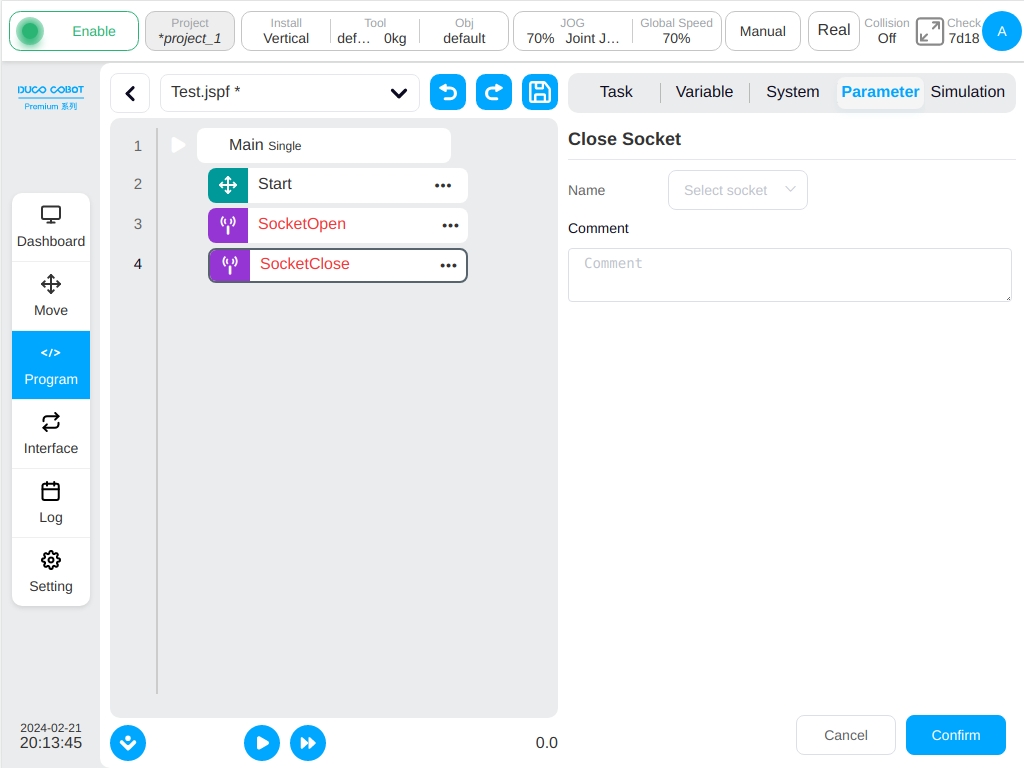
SocketOpen
To create a socket, the parameters page requires the user to set the name of the connection, configure the IP address and port number of the target server choosing whether or not to bind the return value to a variable.

SocketClose
To close the socket connection, select the name of the connection to close.
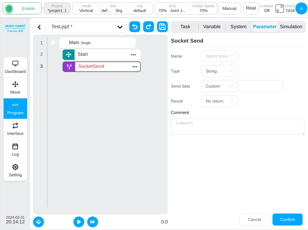
SocketSend
The socket sends data. Send data to an established socket connection. The send type can be a string or a set of floating point numbers. The send data can be a variable or a direct input.
SocketRecv
The socket receives data. Receive data from an established socket connection. The receiving type can be a string, string array or floating-point number group. The receiving information configures the receiving variable.
When the receiving length is specified, the program will receive the data of this length and process it according to the string, saving it to the variable configured in ‘Receive Information’.
If the string array is the type, the program parses the received string into numeric values. All values are in () and separated by commas (,). For example, if a string ‘(12,1.23)’ is received from a socket, the block converts it to num_list with a value of {12,1.23} and saves it to a variable in the ‘Receive Messages’ configuration.
When a floating-point number type is given, the program converts the received data to a set of single-precision floating-point numbers (converted according to the IEEE 754 standard) and saves it to a variable in the ‘Receive Information’ configuration.
The user can configure a timeout period for receiving data. If no data matching the rule is received within the timeout period, the next statement is executed.

CommSend
Recipe data sent. When the formula is set on the 485 or CAN port of the robot, the function block can be used to set values for the data in the formula and send them. The return variable can be set to get the status of the recipe data sent.

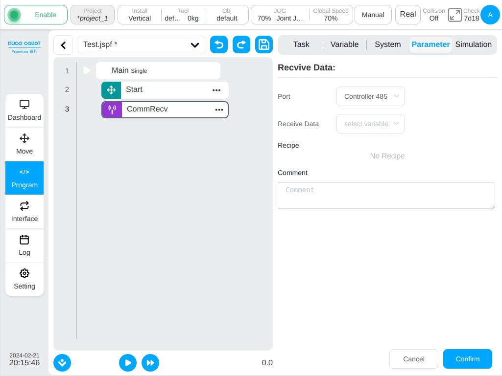
CommRecv
Recipe data reception. When the formula is set on the 485 port or CAN port of the robot, the function block is used to receive data, and after processing according to the formula, the obtained num_list data is assigned to the received variable.
Advanced#
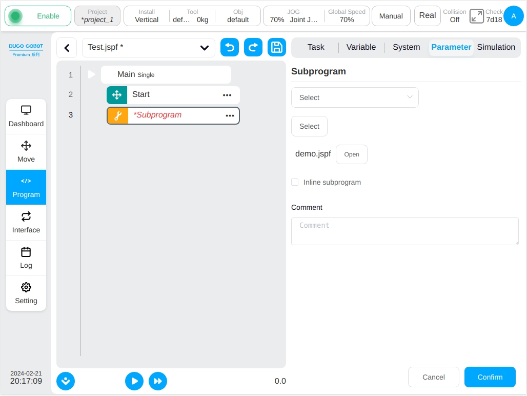
Subprogram
Subroutine. The user can embed other programs into the current program. There are two ways:
Select the embedded subroutine directly from the program list, if the user doesn’t check the ‘Embed the Subroutine’ option, the subroutine will be loaded from the file every time the program runs, i.e., the changes of the subroutine file will affect the main program and the user can open the subroutine file directly by clicking the ‘Open’ button after the subroutine name. Following with the user can click the ‘Open’ button after the name of the subroutine to open the subroutine file directly for viewing. If it is checked, the subroutine is copied directly to the main program, and the changes of the subroutine file will have no effect on it, and the ‘Open’ button will not be displayed after the name of the subroutine.
If the user set it to a string variable, the program dynamically loads the corresponding subroutine based on the value of the variable as the subroutine name at runtime.
Note
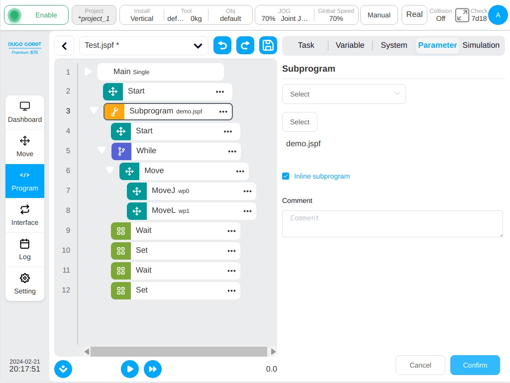
For the “Inline subprogram”, the program variables in the subprogram will also be copied to the main program If there is a variable with the same name in the main program, it may have some impact on the main program. So when you use it, carefully check the behavior of this variable to make sure it doesn’t affect the original execution logic of your program.
Note
When referring to a subprogram with a string variable, do not check “Inline subprogram”
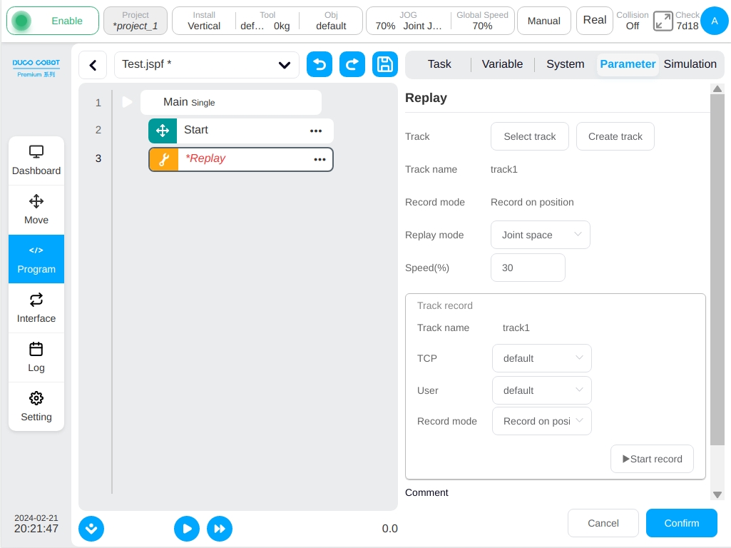
Replay
The trajectory is repeated. It is possible to create a robot motion track whose recording mode is position-based recording or time-based recording. When the program is executed to this function block, the robot moves the trajectory according to the joint space-based or Cartesian space-based reproduction mode. The user can select an existing track file or create a new track.
To create a new track, click the ‘New Track’ button and enter the track name, the ‘Track Record’ box will be displayed. After selecting the tool coordinate system, the workpiece coordinate system and the recording mode, click the ‘Start Record’ button to start recording the track data. At this time, a semi-transparent suspension box will be displayed on the page indicating that the track is being recorded. Click the ‘Stop Recording’ or the ‘Stop’ button on the hover box to complete the creation of the track file. During the track recording process, the user modifies the coordinate system or switches the current coordinate system, terminates the current track recording, and the ‘Track Recording’ suspension frame disappears.
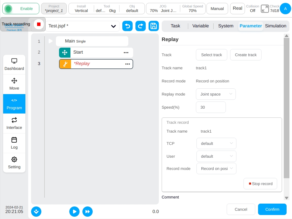
For the selected track, when the recurrence mode is based on the joint space, the track name and recording mode of the track will be displayed. When the reproduction mode is based on Cartesian space, the track name, recording mode, tool coordinate system and workpiece coordinate system of the recording time are displayed.
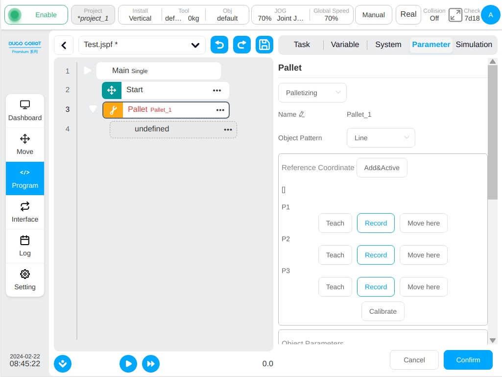
Pallet
Palletizing/unloading. A set of palletizing/unpalletizing standard procedure templates can be automatically loaded and adapted based on some simple parameter settings.
Follow these steps to use the palletizing/unpalletizing blocks:
Determine whether to use palletizing or unloading, palletizing is to move the workpiece to the pallet, unloading is to remove the workpiece from the pallet.
The user can specify the name, each time adding a Pallet will generate a default name.
Select the placement mode of the workpiece on the tray, straight line or grid mode.
The reference coordinate system used by the calibration tray is calibrated based on the first workpiece placed on the tray. P1 point indicates the point of teaching to the workpiece, P2 point indicates the line direction (the X-axis direction of the reference coordinate system), and P3 point indicates the column direction. Click the ‘Calibration’ button to complete the calibration of the coordinate system. The value of the reference coordinate system will be displayed on the top.

Click the ‘Add & Activate’ button, a dialog box will pop up. After entering the name of the coordinate system, it will be added to the system and set as the current coordinate system.

Set the workpiece placement parameters, need to set the height of the workpiece, the number of pieces placed in the direction of the line and column, the spacing of the workpiece in the direction of the line and column.
Set the count variable of the workpiece, need to create a variable of type number in the program variable area.
Set the number of layers.
Define the point of the execution of the action on each workpiece, which can be divided into three approach point, action point and exit point. The three points are shown at the first work piece placed on the tray. The approach point is the position where the robot runs to the top of the tray and plans to place/grab the workpiece; The action point is the position where the robot places/grabs the workpiece; The exit point is the position when the robot leaves the tray after placing/grasping. Note: These three points must be taught in the tray’s reference coordinate system.
After the teaching is completed, click the ‘Generate Script’ button which will automatically add a series of function blocks in the program.
The Group function block can add corresponding execution actions such as clamping claw opening and closing.

the program is set to the cycle mode, the palletizing program will be executed each time, according to the parameters set to calculate the offset, determine the next palletizing/unloading position attitude. In the Variables area, the number of currently palletized/unpalletized workpieces can be viewed according to the workpiece count variable set
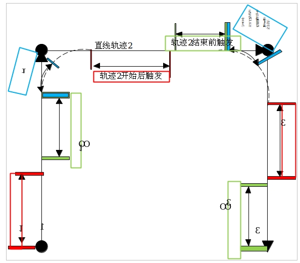
RecordPoseTrans
Operation point conversion teaching function block. Used to do point conversion.
In the figure below, point O is the reference point, and the pose of points A, B, C, and D with respect to reference point O is unchanged. The operation point conversion teaching function block records the relative pose relationship of these points relative to reference point O, and outputs the pose of A ‘, B ‘, C ‘and D’ points when the pose of O changes. It is commonly used in visual identification positioning, laser locating and other occasions. For example, in the visual identification positioning scene, reference point O is the marker block of A station, and A, B, C, and D are the four workpieces of the station, and the workpieces are fixed relative to the pose of the marker block. The pose of the marking block in the robot base coordinate system is identified by the camera, and the pose of the workpiece in the robot base coordinate system is calculated by the operation point teaching function block.
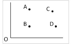
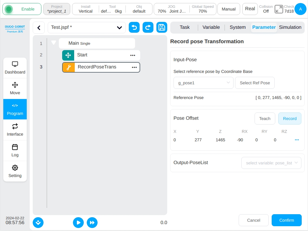
The configuration page is shown in the figure, which consists of three parts: the reference point (O point) is set in ‘Input-reference Pose’, the operation point (A,B,C,D) is set in ‘Operation Point Offset’, and the variables are set to store the calculated operation point (A ‘,B ‘,C ‘, and D ‘) in ‘Output-conversion Pose’. In the configuration phase, the function block will record the deviation of the operating point (A,B,C,D) from the reference point (O); When the program is running, the pose of the operation point (A ‘,B ‘,C ‘,D ‘) is calculated according to the value of the current input variable (O ‘point) plus the deviation.
Select a pose type global variable as the reference pose, click the ‘Set as Base’ buton, the current value of the variable will be used as the reference base (O point). Click the ‘Teach to Add’ button in the operation point offset to jump to the mobile page, the user can move the robot to select A point (A,B,C,D), and a new point is added after selection and the configuration page will display the value of the added point under the base label. In the output field, select A pose_list variable to store the results of the calculation (A ‘,B ‘,C ‘,D ‘).
Force control related scripts
The current Force control related scripts include Force, ForceGuard, ForceSetZero, ForceWait, ForceMove. For a detailed application, please refer to the ‘DUCO CORE Terminal Force Control Function Manual’.
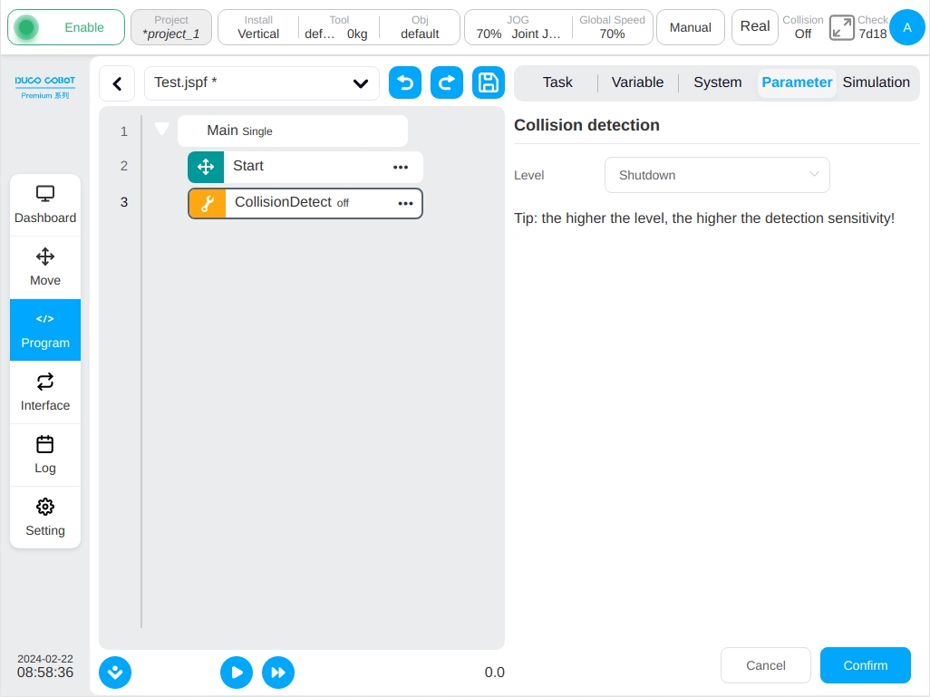
CollisionDetect
Collision detection level. The script can realize the collision detection sensitivity setting during the program running.
Note
The parameters set in this function block only affect the robot startup state and will not be saved when powered off. If you want to permanently set the collision detection sensitiviry, set it in”Settings”-“Other Settings” -“Collision Settings” and save the project.
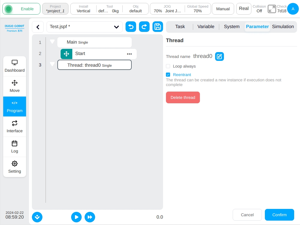
Thread
Threads, which execute in parallel with the main robot program, interact with the main program through variables. In the parameter configuration area, the user can set whether the thread keeps looping, also can set whether the thread is reentrant, that is, whether the thread can create a new instance of execution if the execution has not completed. Creating a maximum of 10 threads in a program is also possible.
Note
Robot motion block are not allowed in the thread.
Variable Area#
This page allows you to create program variables and monitor program variable values. Program variables are different from system variables in that system variables act on the whole project, while program variables exist only within the program.
Add Variable#
Click the ‘Add Variable’ button to bring up a dialog box, as shown in the figure, entering the variable name, selecting the type, and giving the initial value can be created.
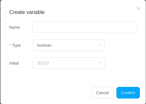
Program variables have the following types:
boolean: Boolean. The value can only be false or true
number: Indicates the number type
string: Indicates a string type
num_list: Array type
pose: A data type that represents the Cartesian position of the robot
joints: A data type of robot joints
joints_list: Indicates the data type of robot joint position list
pose_list: Indicates the Cartesian position list data of the robot
pose_speed: Indicates the data type of the speed of the end of robot
pose_acc: Indicates the data type of the acceleration at the end of robot
joint_speed: Indicates the data type of the angular speed of the robot joint
pose_acc: Indicates the data type of the angular acceleration of the robot joint
Variable Monitor#
When the ‘Variable Monitor’ is checked, the current values of the program variables are displayed on this screen while the program is running. Clicking the ‘Sort’ button also allows the user to sort the names of program variables alphabetically.
Note
joints and pose variables should be monitored as num_list and the data unit are m/rad.
When the ‘Variable Monitor’ is unchecked, the efficiency of executing scripts will be greatly improved by saving the process of synchronizing program variables and displaying them to the interface.
Run#
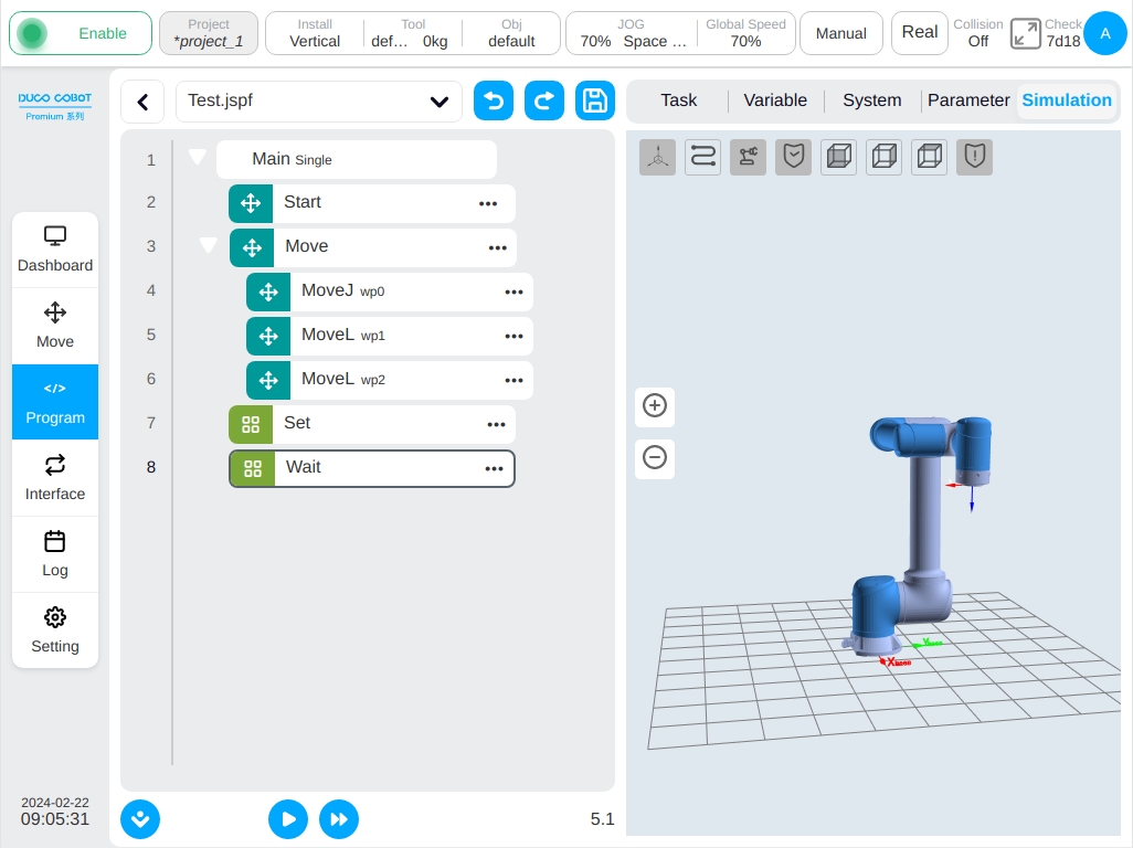
Click on the “Simulation” TAB to go to the 3D model page, which shows the 3D model of the robot.
The icon at the bottom left of the program tree controls the start and stop of the program,
click icon  button to run the program, click icon
  button steps the program.
You can pause or stop the program at any time while it is running.
Tap icon
button steps the program.
You can pause or stop the program at any time while it is running.
Tap icon  button set the program running process, the cursor automatically follow the command block,
click icon
button set the program running process, the cursor automatically follow the command block,
click icon  enable automatically followed of program running, and it is turned on by default.The gray icon represents the feature is turned on while the blue icon represents the feature is turned off.
Run the Program#
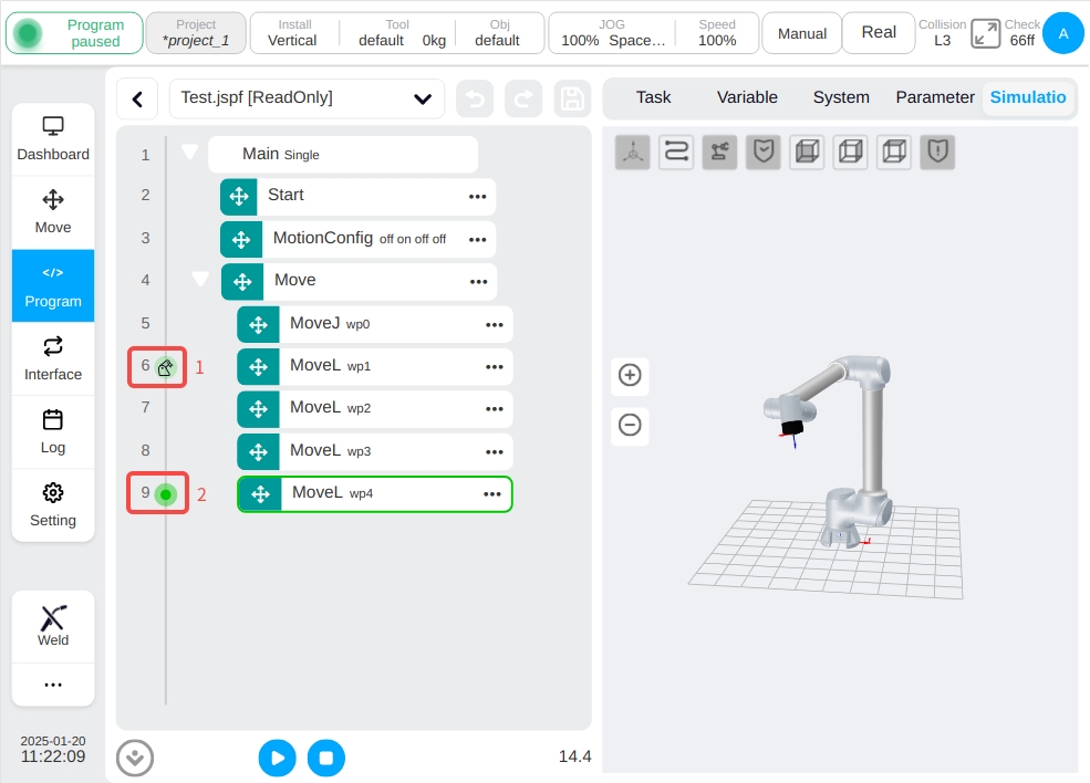
When running the program, it will check whether the starting point of the program is consistent with the current point of the robot. If not, it will first move to the starting point, as shown in the figure, the robot at the starting point will be displayed in the 3D model (gray display). Click the ‘Hold Down to Move’ button and the robot will move to the starting point.
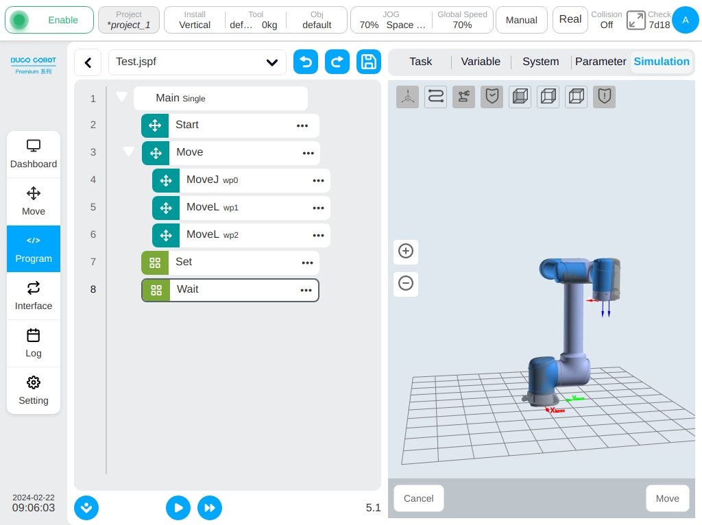
Once the user have moved to the starting point, click icon button again to run the program. In the figure below, the running time of the program can be displayed on the lower left side of the program tree. The real-time posture of the robot can be observed on the 3D model. The function blocks correspond to the currently robot motion and the executed script can be displayed on the left side of the program tree simultaneously.
That is, 1 place in the figure is the position of the motion pointer, indicating the motion instruction that the robot is currently executing, and 2 places in the figure is the position of the program pointer, usually the motion pointer is one or several instructions behind the program pointer, because the controller executes and calculates the robot path faster than the execution and calculation of the robot movement instruction.
Click the control button below to suspend, resume and stop the program.
Single Step Program#
Clicking icon button to run the program step by step. When single step, the starting point of the program is first checked and the robot is moved to the starting point position of the program. Each time clicking icon , the program will execute a function block down. Clicking icon button, the program will exit the single step mode, continuous running. The program can be paused and resumed in a single step process. Clicking icon  will perform the backward operation and the robot will move backward to the previous point and the backward action is only for the motion function block.
Clicking stop button  , the program stops running, exit the single step state.
Break Point#
Support breakpoint debugging function, program execution to the breakpoint location, will stop and enter a single step mode.
The user can set break points in the program tree and script editing area, clicking the left area of the program tree line number, the left area of the script line number to hit the breakpoint, clicking the breakpoint again to cancel the breakpoint. Clicking the icon  below button can cancel all breakpoints set by the system.
Process the program, when the program runs to the breakpoint, the program will stop and enter the single step mode, as shown in the figure. Clicking icon button, the program will be executed in a single step, (run to the Script function block, will be executed in a single line); Clicking icon button the program will continue running until the next breakpoint is reached or the program ends.
In manual mode, the user can set break points or cancel breakpoints at any time while the program is running.