Interface Page#
Clicking the ‘Interface’ button in the navigation bar will default to the I/O sub-page under the interface page. There are 6 sub-pages under Interface page, including I/O, Register, CCI, TCI, TCP/IP and Industrial Bus. According to the control cabinet model, there are two types of pages, as shown in the figure:
Suitable for DC30D control cabinet
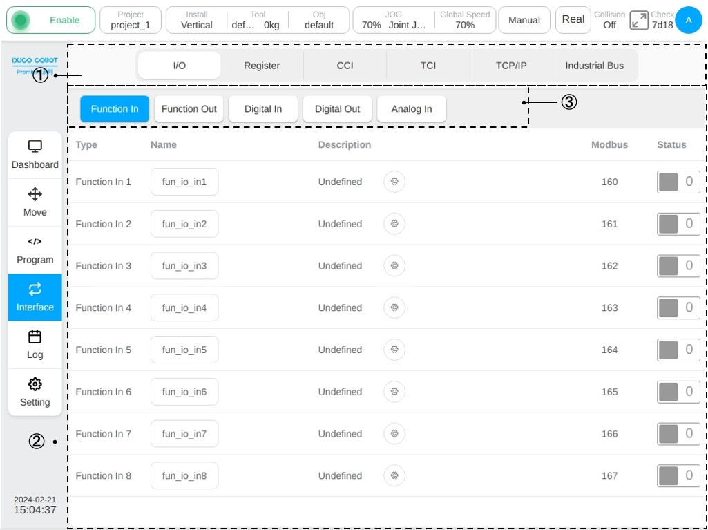
Suitable for DC00 / DC15S-J9 / DC30D-J9 control cabinet
The upper part of the page (1) is the sub-page TAB of the interface page and the lower part (2) is the display area of the corresponding sub-page. When the user selects a different subpage option, area ② corresponds to the display content switched to this option.
IO#
Area ② in the figure shows the corresponding contents of different tabs of the I/O subpage, above of it is the display area of the I/O subpage, ③ is the label made under the I/O subpage for different inputs and outputs.
For the DC30D control cabinet, there are five types of function input, function output, general input, general output and analog input in the I/O subpage. Click different label bars to switch and display five types of input or output status information.
The function input interface can monitor the status and basic information of the 8-way digital input that can set a certain function in the control cabinet. Click a function to enter a name. A common virtual keyboard is displayed. The user can modify the default name of the function. After the default name is entered for the modification function, the icon ① shown in the figure will be displayed on the right of the name display box. Click the icon to restore the function input name to the corresponding default name.
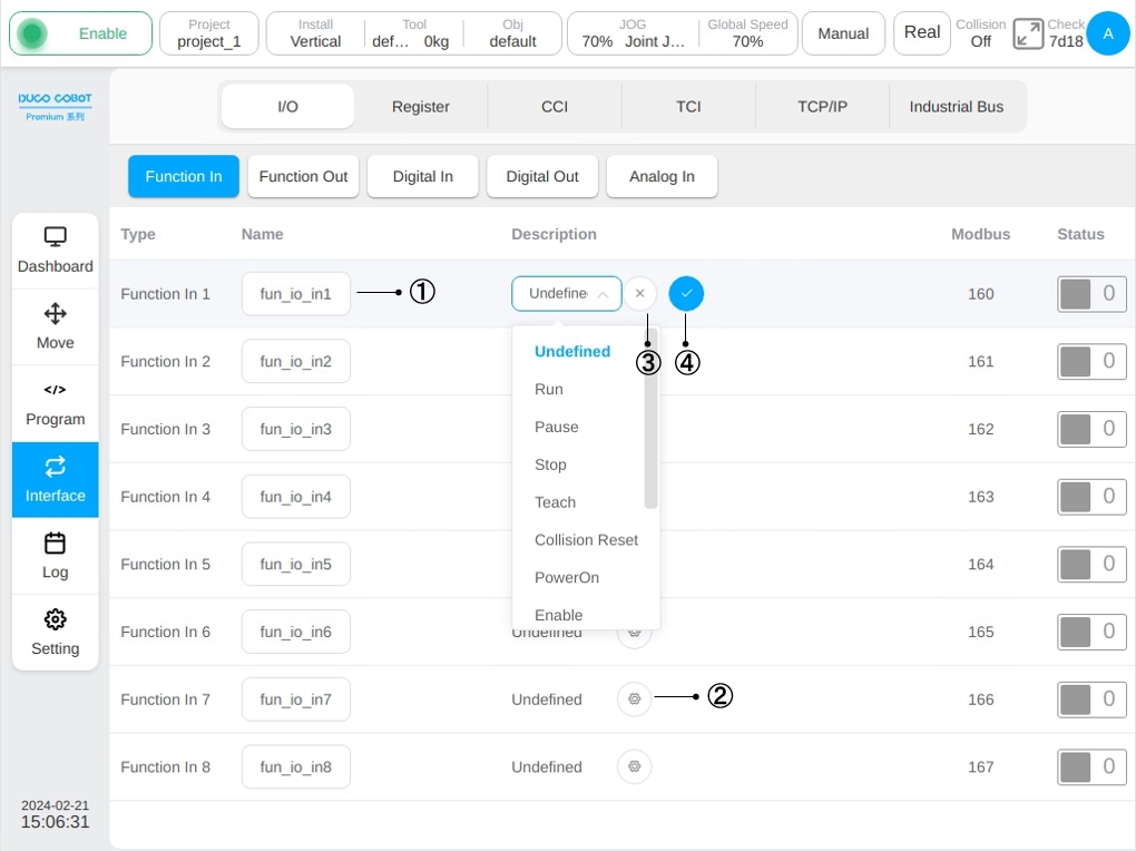
Click the corresponding function input icon ② in the figure, the function settings selector, icon ③ and icon ④ will be displayed and the user can select the function settings of the function input. Select the function in the display function selector drop-down box and enter the function item you want to set. Click the icon ④ to determine the selected function item. You can also deselect the selected feature by clicking icon ③. When the function input signal is triggered, the set function is activated. At present, the function input supports the following functions: Run , Pause , Stop , Teach, Collision Reset, PowerOn, Enable, Disable, PowerOff, Shutdown, Record Pose, Home, Abort Move.
Note
Run, Pause, Stop, Abort Move is triggered by rising edge trigger signals.
Note
Abort Move command only takes effet to the move task which is currently executing by robot when command signal is triggered. If a program is running, the following scripts will continuous keep running.
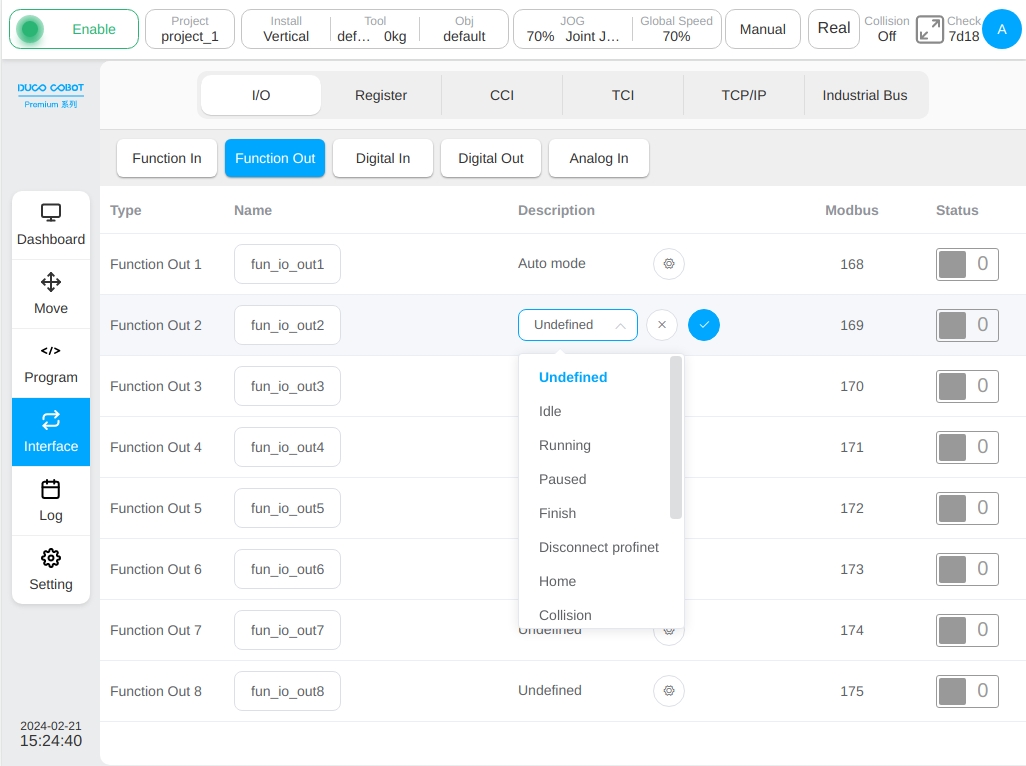
The function output interface can monitor the status and basic information of the 8-way digital output that can set a certain function in the control cabinet, as shown in the figure. Similar to the function input interface, you can modify the corresponding name of the function output and select the function Settings of the function output. In the function Settings selector drop-down box, select the predefined system status quantity bound to the function output. After clicking the ‘OK’ icon, the function output will reflect the status of the set system status quantity. At present, the function output supports binding states: Idle, Running, Paused, Finish, Disconnect profinet, Home, Collision, Auto mode, PowerOff, Disable, Robot moving, Disconnect ethernet, Robot power, Handling, Move Aborted.
Note
The Move Task Aborted signal will only be true when robot is currently executing a move task and the motion task is aborted by a move task abort command from function IO input, function register input or other interface. The Move Task Aborted signal only can be reset through reset the function IO input or function register input, which is configured as the source of move task abort command, and the function IO output is reset low at the same time.
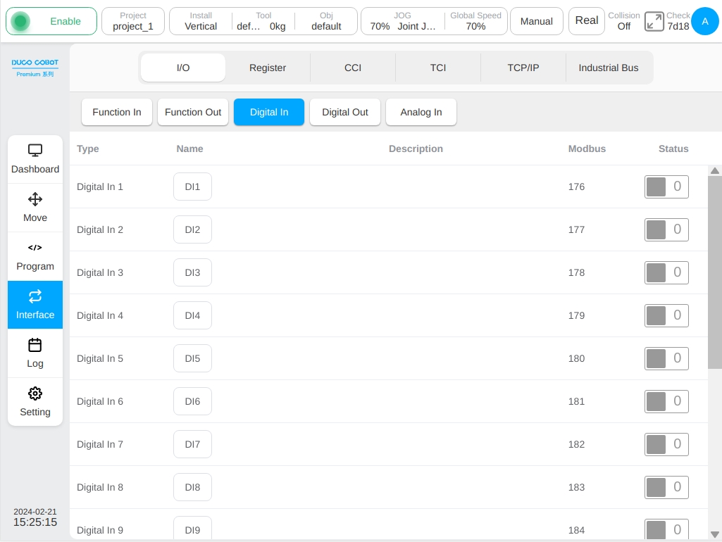
The general input interface can monitor the status and basic information of the ordinary 16-way digital input in the control cabinet, as shown in the figure. Different from the function input and function output interfaces, only the corresponding name and the modified recovery of the input signal can be modified, and specific functions cannot be set.
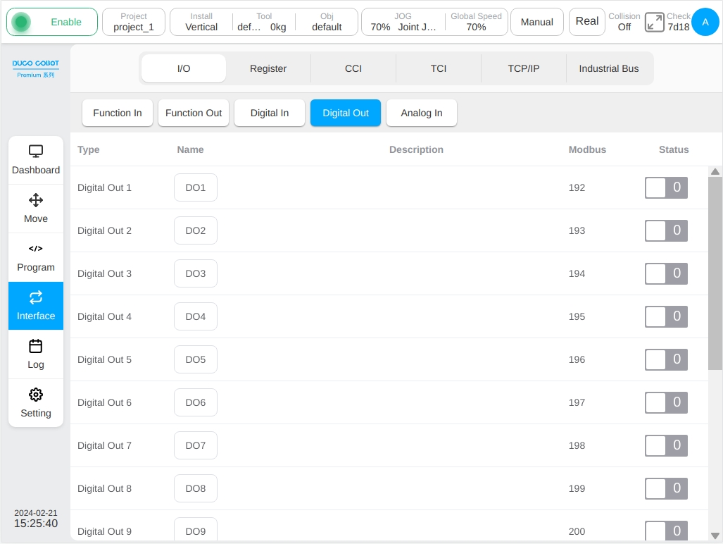
The general output interface can monitor the status and basic information of the ordinary 16-channel digital output in the control cabinet, as shown in the figure. The interface can only modify the corresponding name and restore the output signal after modification, and can not set specific functions.
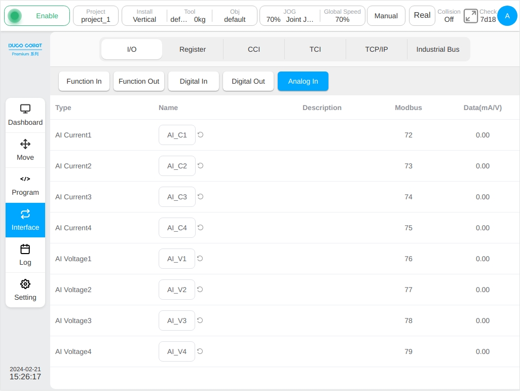
The analog interface can monitor 4 analog current input signals and 4 analog voltage input signals, as shown in the figure. Similarly, click the analog input signal name display box to modify the signal name. Operations are similar to the functional I/O and generic I/O described above and are not repeated here.
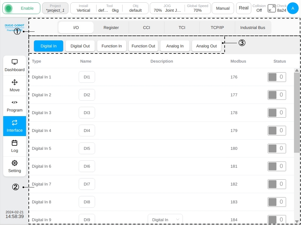
For DC00 / DC15S-J9 / DC30D-J9 control cabinets, there are six types of general input, general output, function input, function output, analog input, and analog output in the I/O subpage. Click different label bars to switch and display six types of input or output status information.
The general input interface can monitor the status and basic information of the ordinary 16-way digital input in the control cabinet, as shown in the figure. The eight digital input types DI9 to DI16 can be configured as function input or general input in the description column ① of the page.
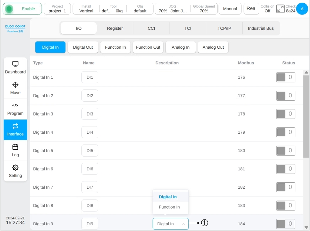
If the user select each digit input as function input, the digit input status is disabled on the I/O General input page and the digit status configured as function input is displayed on the function input sub-page. For example, if DI9 and DI10 are configured as function input, the function input TAB page under the I/O sub-page is shown in the following figure.
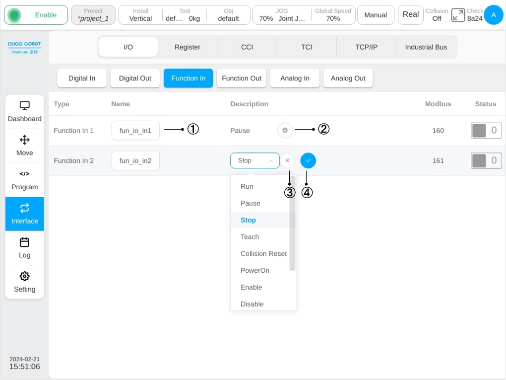
Similarly, clicking a function input name will bring up a normal virtual keyboard, and the user can modify the default name of the function input. After you enter the default name for the modified function, the icon ① in the above figure is displayed on the right of the name display box. Click the icon to restore the function input name to the corresponding default name.
Click the corresponding function input icon ② in the figure, the function settings selector, icon ③ and icon ④ will be displayed, and you can select the function Settings of the function input. Select the function in the display function selector drop-down box and enter the function item you want to set. Click the icon ④ to determine the selected function item. The user can also deselect the selected feature by clicking icon ③. When the function input signal is triggered, the set function is activated. The current function input supports the following functions: Idle, Running, Paused, Finish, Disconnect profinet, Home, Collision, Auto mode, PowerOff, Disable, Robot moving, Disconnect ethernet, Robot power.
Note
Run, Pause, Stop is triggered by rising edge trigger signals.
The universal output interface can monitor the status and basic information of the ordinary 16-channel digital output in the control cabinet, as shown in the figure. The DO9-DO16 digital input types can be configured as function input or general input in the description column ① of the page.
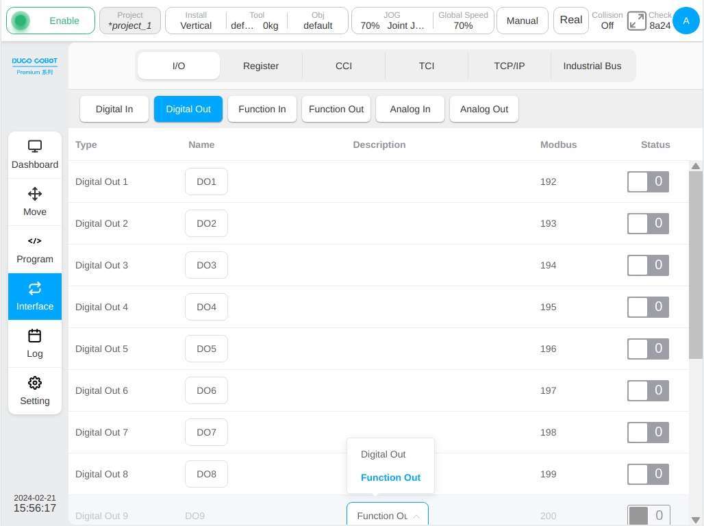
Similarly, if each general digital output is selected as function output, the digital output of this path is displayed as disabled on the I/O General output page, and the digital status of each path configured as function output is displayed on the function output sub-tab page. For example, DO9, DO10, DO11, and DO12 are configured as function output. The following figure shows the function output TAB page of the I/O subpage.
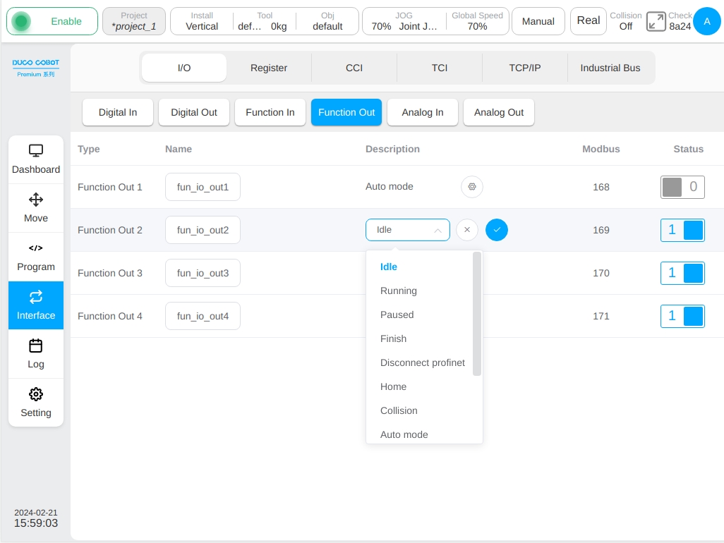
In the same way as the function input TAB, click the function output name, and a common virtual keyboard is displayed. The user can modify the default name of the function output. After the default function output name is changed, icon ① in the above figure is displayed on the right of the name display box. Click the icon to restore the function output name to its default name.
Click the corresponding function output icon ② in the figure, the function Settings selector, icon ③ and icon ④ will be displayed, and the function Settings of the function output can be selected. In the display function selector drop-down box, select the function item that the function output wants to set. Click the icon ④ to determine the selected function item. The user can also deselect the selected feature by clicking icon ③. When the function output signal is triggered, the set function is started. At present, the function output supports the following functions: idle state, program running state, pause state, program end, profinet disconnect, Home position, collision, automatic mode, not powered on, not enabled, robot movement, ethernet/ip disconnect, robot 48V power status.
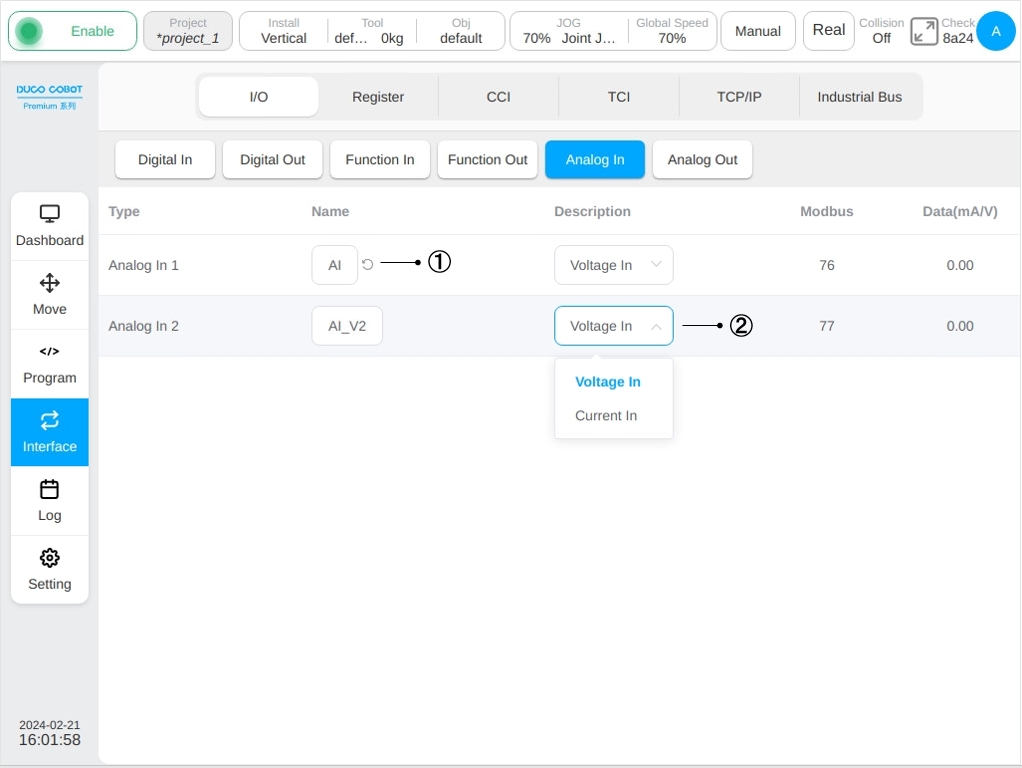
The analog input interface can monitor 2 analog input signals, as shown in the figure. Similarly, click the analog input signal name display box to modify the signal name. After modifying the analog input default name, icon ① in the figure will be displayed on the right side of the name display box. Click the icon to restore the analog input name to the corresponding default name. And the analog input signal can be explained in the description column icon ② to select the voltage input or current input.
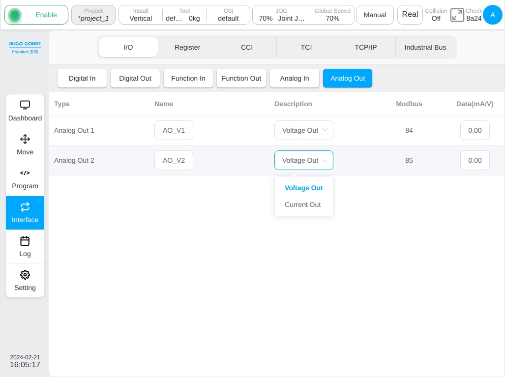
The analog output interface can monitor 2 analog output signals, as shown in the figure. Similarly, click the analog input signal name display box to modify the signal name. The operation is similar to the analog input described above and is not repeated here. And the analog output signal can be explained in the description column configuration selection, the user can choose the voltage output or current output.
Register#
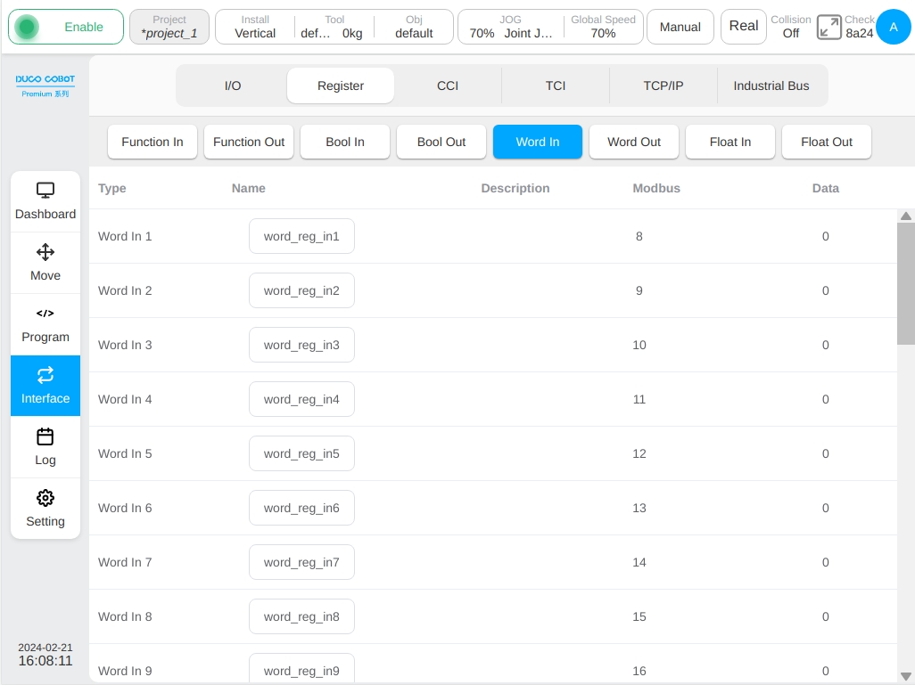
The register subpage is similar to the I/O subpage, the upper part of the page is labeled for different types of inputs and outputs, which are: Function Inputs, Function Outputs, Bool Inputs, Bool Outputs, Word Inputs, Word Outputs, Float Inputs and Float Outputs, totally 8 types. Click on the different tabs to switch the display of the eight types of input or output data information.
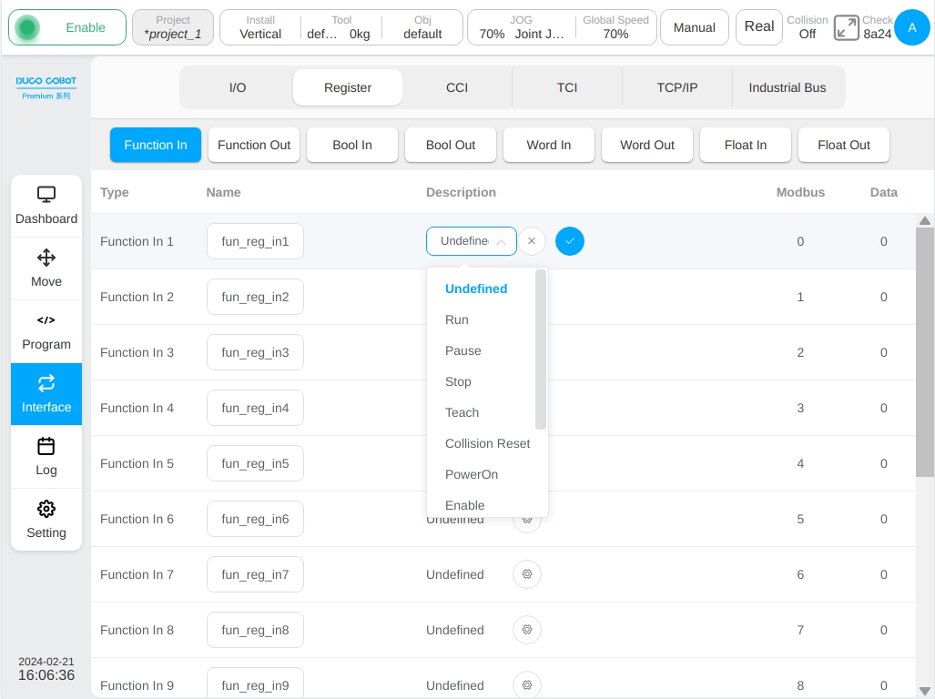
The register function input interface can monitor the status information of 16 function input registers inside the robot, as shown in the figure. The same as the function input of the I/O subpage, the function input name can be modified and restored after modification and specific function items can be set for this type of register signal. The function items currently supported by the register function input are the same as the function input support functions in the above I/O subpage.
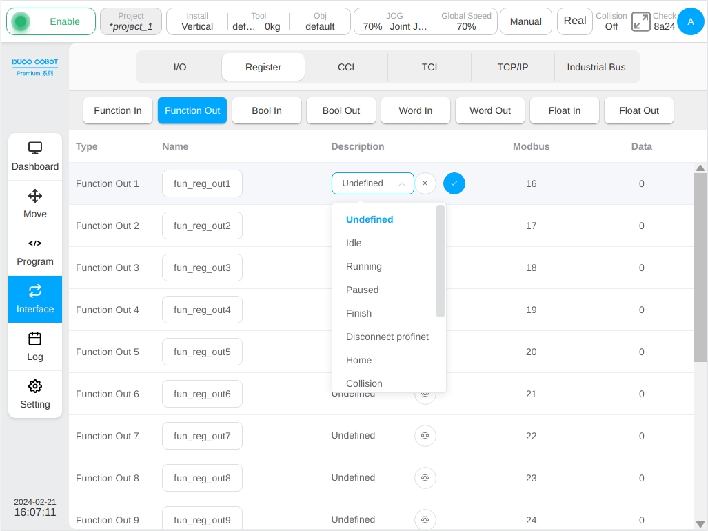
The register function output interface can monitor the status information of 16 function output registers inside the robot, as shown in the figure. Like the function output of the I/O subpage, the function output name can be modified and restored after modification, and the class register signal can be bound to a specific system predefined state quantity. At present, the binding states supported by the output of the register function are: Idle, Running, Paused, Finish, Disconnect profinet, Home, Collision, Auto mode, PowerOff, Disable, Robot moving, Disconnect ethernet, Robot power, Handling, Move Aborted.
Note
The Move Task Aborted signal will only be true when robot is currently executing a move task and the motion task is aborted by a move task abort command from function IO input, function register input or other interface. The Move Task Aborted signal only can be reset through reset the function IO input or function register input, which is configured as the source of move task abort command, and the function register output is reset low at the same time.
Register Bool Input interface Displays the status information of 64 Boolean input registers. The interface can modify and restore the register name after modification, and cannot set specific function items.
Register Bool Output interface Displays the status information of 64 Boolean output registers. Similarly, the interface can only modify and restore register names after modification, and cannot set specific function items.
Registers Word Input interface and Float Input interface display 32 byte type input register and 32 floating point type input register status information respectively. They can only modify the register name and modify the recovery, do not have the specific function of setting and can not operate the data column data display box.
Register Word Output interface and Float Output interface display the status information of 32 byte type output register and 32 floating point type output register respectively. Similar to the register Bool output interface, they can modify the register name and restore it after modification and can also operate the data column data display box.

CCI#
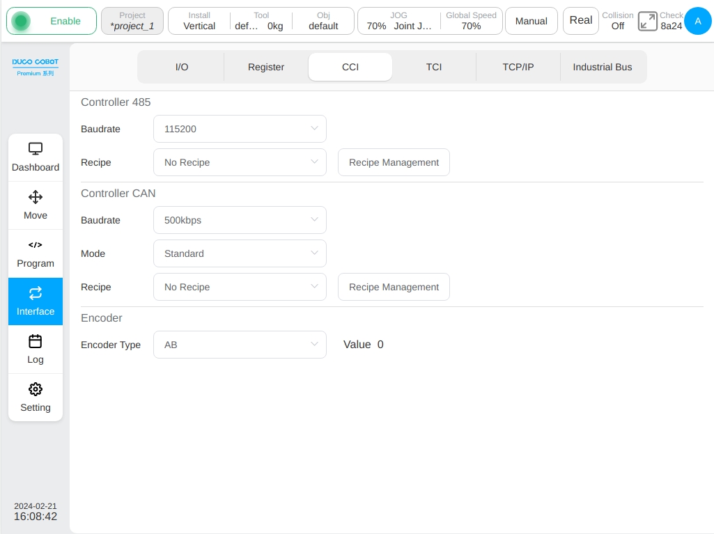
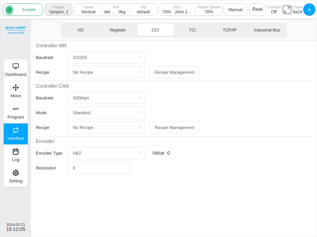
The CCI sub-page is to configure the 485 port, CAN port and encoder interface of the control cabinet, mainly to set the baud rate and mode configuration, formula and set the encoder type of the 485 port and CAN port of the control cabinet. As shown in the figure.
The baud rate for port 485 of the control cabinet can be selected from the baud rate selector drop-down list. Port 485 supports baud rates of 9600, 19200, 38400, 57600, and 115200. Select the recipe file for the port in the recipe selector drop-down box.
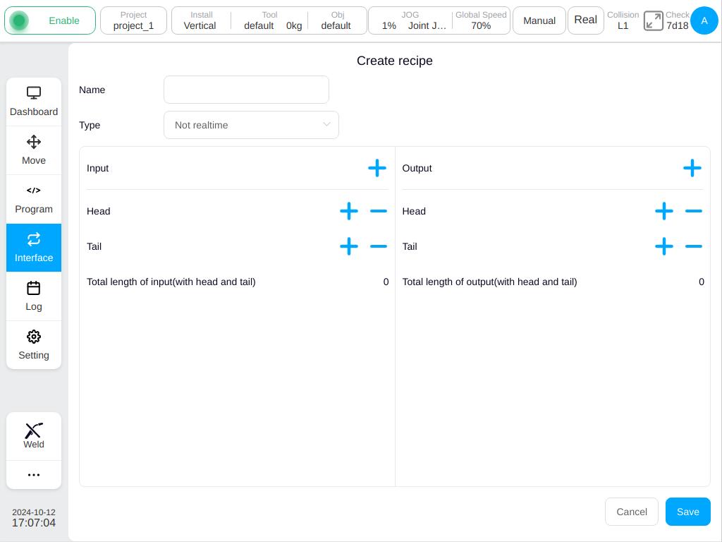
As shown in the image above, the drop-down box displays the recipe file name which is defined by the user. Click the ‘Formula Management’ button and the formula management list box will appear. The interface displays the existing formula files in the current project. Users can add, delete and edit the formula.
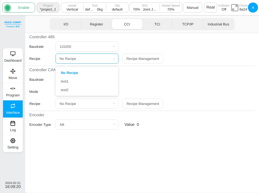
Click any recipe file in the recipe list and a pop-up box containing ‘Edit’ and ‘Delete’ buttons will be displayed on the right side. Users can modify or delete the existing recipe file.
The baud rate and formula settings of the CAN port of the control cabinet are similar to those of the 485 port and are not discussed here. The baud rates of CAN ports are 10kbps, 20kbps, 50kbps, 100kbps, 125kbps, 250kbps, 500kbps, and 1000kbps. There are two modes of CAN configuration: standard frame and extended frame.
There are two types of control cabinet encoder configurations namely AB and ABZ. The number of encoder pulses recorded by the current system is displayed on the right side of the encoder. If the encoder type is set to ABZ, the user also needs to set the number of encoder lines. The default value is 0.
TCI#
The TCI sub-page displays the end board IO information, end reusable interface related information. The end board has 2-channel tool inputs and 2-channel tool outputs, which are the same as the general-purpose input/output signals in the I/O sub-page. This interface allows the user to modify the tool input and tool output names and restore the default names after modification. The user can configure the tool output mode, and the 2-channel tool output configuration mode will be forced to be unified, that is, configure any tool output mode to PNP mode or NPN mode, and the other tool output mode will be changed accordingly. The user can also set the tool output status, 0 means low level electronics and 1 means high level electronics, as shown in the figure.
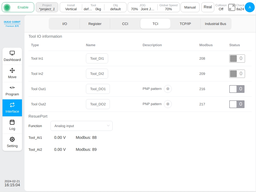
Before use, the user can configure the end interface function is analog input or 485 interface and obtain the corresponding signal according to the configuration. As shown in the figure above, when the terminal interface function is set to analog input, the interface displays the data of the two analog voltage inputs and the corresponding Modbus addresses in real time. If the end interface is set to 485, the interface displays the baud rate and formula configuration information, as shown in the following figure.
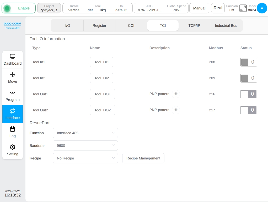
The baud rate and formula can be set at the end 485 interface. The specific operation is similar to the setting of the 485 port of the control cabinet in the CCI subpage, which is not discussed here.
TCP/IP#
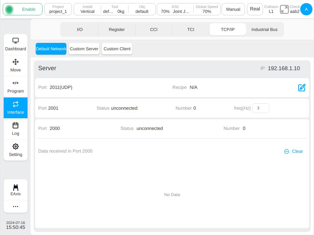
The TCP/IP subpage mainly displays the external TCP/IP connection information of the robot. It mainly contains three subtabs: Default Network, Custom Server, and Custom Client.
The default network subtab page displays information about ports 2000, 2001, and 2011 as a server. Displays the connection status and number of connections for the system IP, 2000 and 2001 ports.
Note
The IP address displayed on the server corresponds to the IP address of the LAN1 network pont. For LAN1’S address settings, refer to “Netwotk Settings”.
Port 2000 can receive the robot’s control commands. The information received by port 2000 is displayed in the lower part of the page.
By default, port 2001 will send out the current status information of the robot at a frequency of 10Hz, the frequency can be set, and the range is 1hz-100hz
The port 2011 is a UDP port that allows you to control the robot through data items configured in the recipe.
For details on how to use ports 2000 and 2001, see the Description of External Communication Interfaces for collaborative robot.
For details on how to use the port 2011, see the recipe instructions.
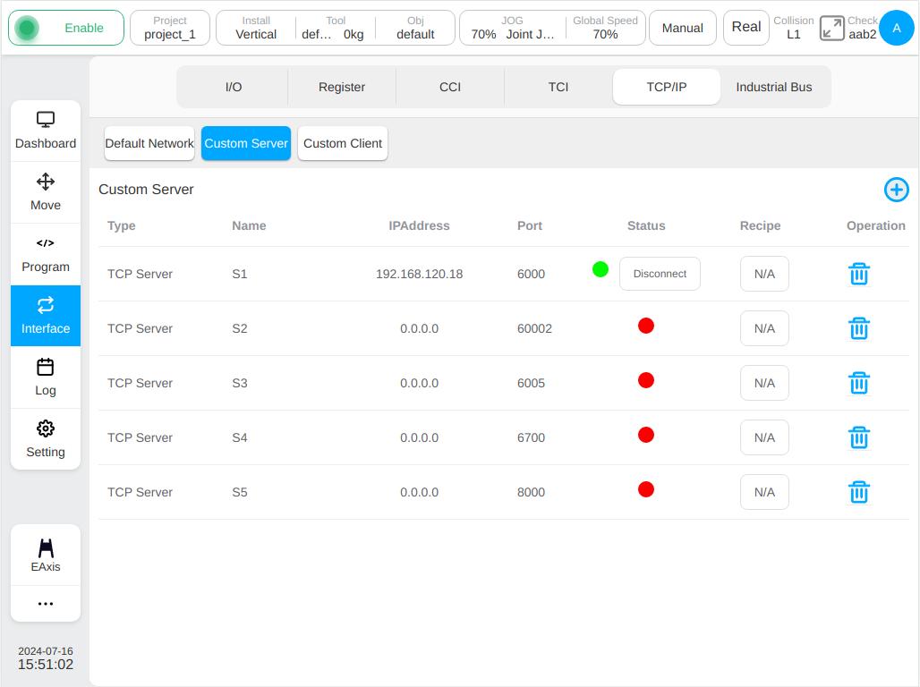
The Custom Server subtab displays the list of socket servers created by the user, including the custom server type, name, connected client IP address, port, connection status, recipe, and operation icon.
When the connection status light is green, you can click the “Disconnect” button on the right side of the status light to disconnect.
Click the Recipe button to set the recipe, and click the action column  icon to delete the added custom server.
Click
icon to delete the added custom server.
Click  icon at the top right of the page will pop up a pop-up window to add a connection, enter the name and port number, and click the “OK” button to add a custom server.
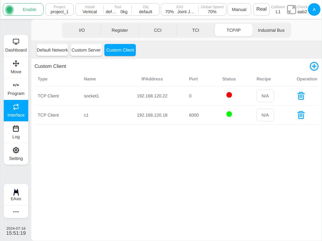
The Custom Client subtab displays all the connection information of the robot as a client, including the type of custom client (TCP/UDP), name, IP address, port, recipe, and operation icon.
Click the Recipe button to set the recipe, and click the action column icon to delete the added custom client.
The connection can be established in the program by using a script or by clicking icon at the top right of the page to build.
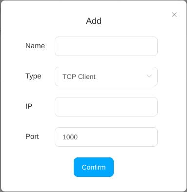
Click icon will pop up the following dialog box, enter the connection information and click the ‘OK’ button to create a connection.
Industrial Bus#
The industrial bus subpage mainly contains four subtabs: Modbus TCP, Modbus RTU, Profinet, Ethernet/IP.
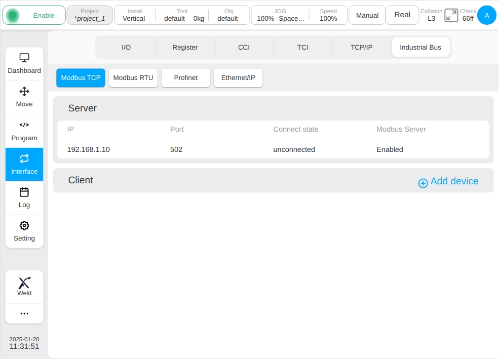
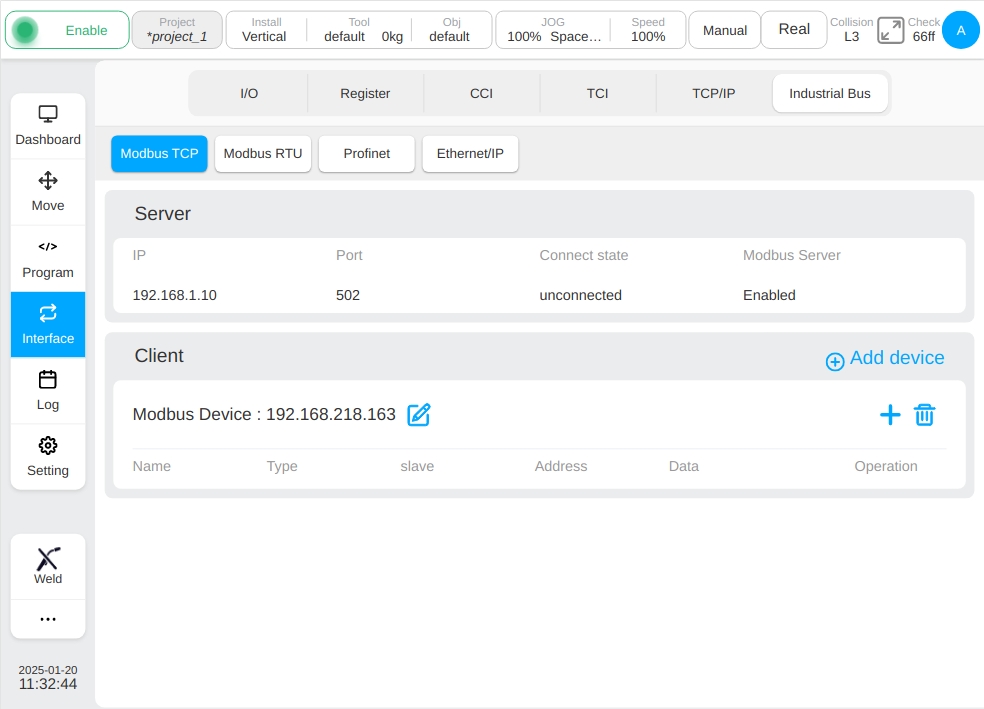
Using the Modbus TCP Function, robot system can worked as a Modbus server to listen to the command from external Modbus Client device and monitor the connection status when the robot is in power on status,. The value of target Modbus address register will be operated based on the r/w command from Modbus Client. As shown in the figure below, the information of Modbus TCP connection and feasible operation are displayed:
Using the Modbus TCP Function, robot system can worked as a Modbus client to connect to the external external Modbus Server device. It is able to operate the target Modbus address register.
The system IP address, port number, and connection status of the Modbus server are displayed in the upper part of interface. Click Add Device. The virtual common keyboard is displayed. Enter the IP address of the external Modbus client device, for example, 192.168.218.163. The Modbus device IP address and related ICONS are displayed on the interface.
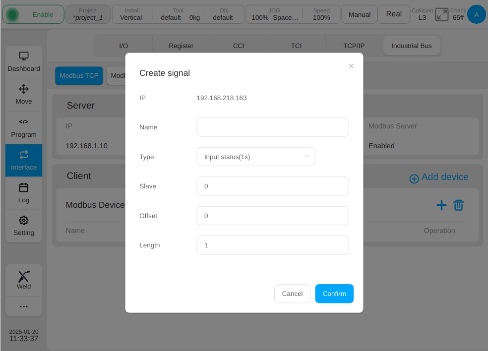
Click icon  the New Modbus node window is displayed, as shown in the figure. Enter the node name, node type, slave number, offset address and length,
with clicking the ‘OK’ button to confirm. There are four node types: read-only coil(1x), read-write coil(0x), read-only register(3x), and read-write register(4x).
the New Modbus node window is displayed, as shown in the figure. Enter the node name, node type, slave number, offset address and length,
with clicking the ‘OK’ button to confirm. There are four node types: read-only coil(1x), read-write coil(0x), read-only register(3x), and read-write register(4x).
When creating a node, the length is 1 by default. When the length value is 1, a single node is created. If the length is greater than 1, multiple nodes are created in batches. If the length is set to 3, add underscores (_) to node names according to the length, that is, node_1, node _2, and node _3, and the addresses are 0, 1, and 2 in sequence, as shown in the figure.
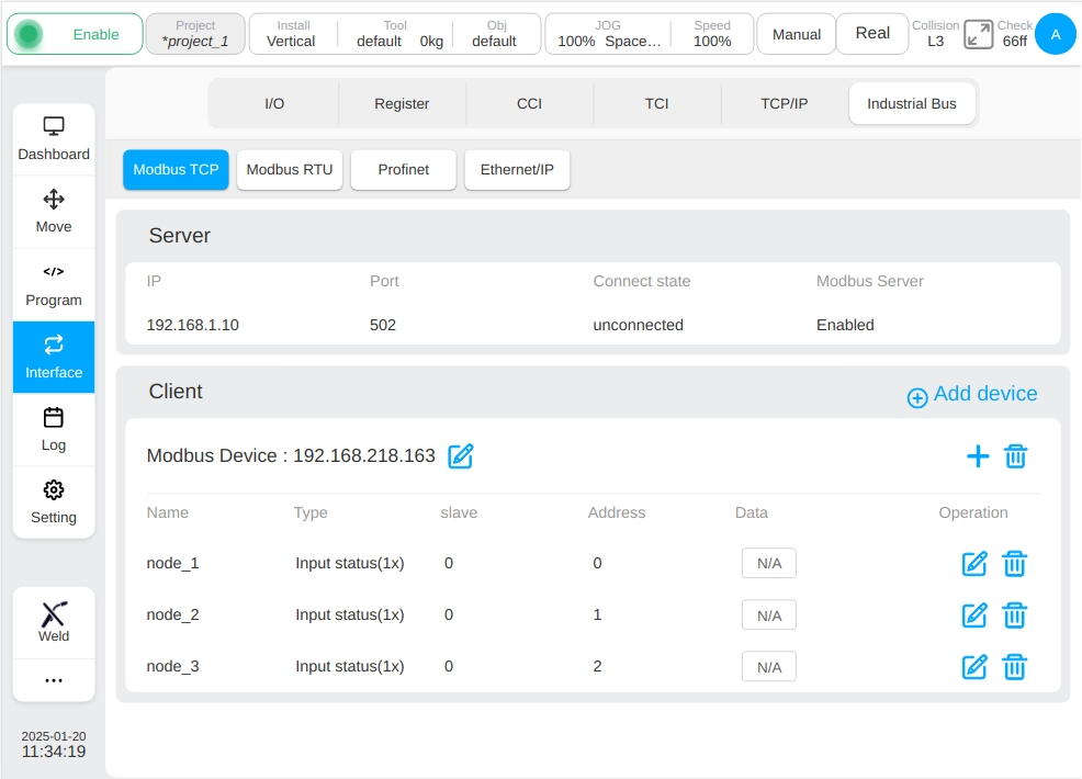
After a new node is created, the information about the newly defined node is displayed on the interface. If no data is displayed in the data column, N/A is displayed.
The user can modify or delete each node. Click the button  of the corresponding node row, and the pop-up window is similar to that when a new node is created,
except that the node name cannot be changed, the length is not displayed, and the node type, slave number, and offset address can be changed.
of the corresponding node row, and the pop-up window is similar to that when a new node is created,
except that the node name cannot be changed, the length is not displayed, and the node type, slave number, and offset address can be changed.
The user can change the IP address of the newly created Modbus device.Click the icon after the IP address of the Modbus device, The virtual common keyboard will pop up,
enter the target IP address, such as: 192.168.218.168. After clicking the “OK” button, the interface will be displayed as follows.
After the IP address of a Modbus device is modified, the node information of the new IP address is the same as that before the IP address is modified.

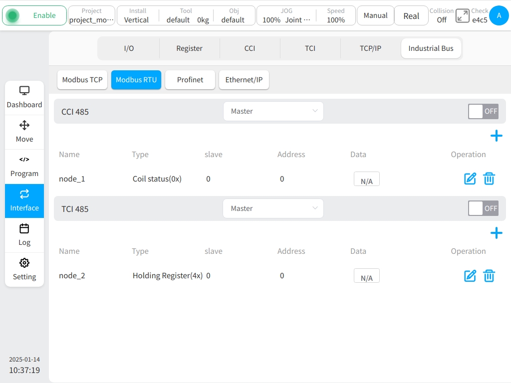
Using Modbus RTU Function, robot system can work as a Modbus Slave through controller 485 interface and robot tool 485 interface when robot is in power on status. The external Modbus Master divice can read and write register through target Modbus address.
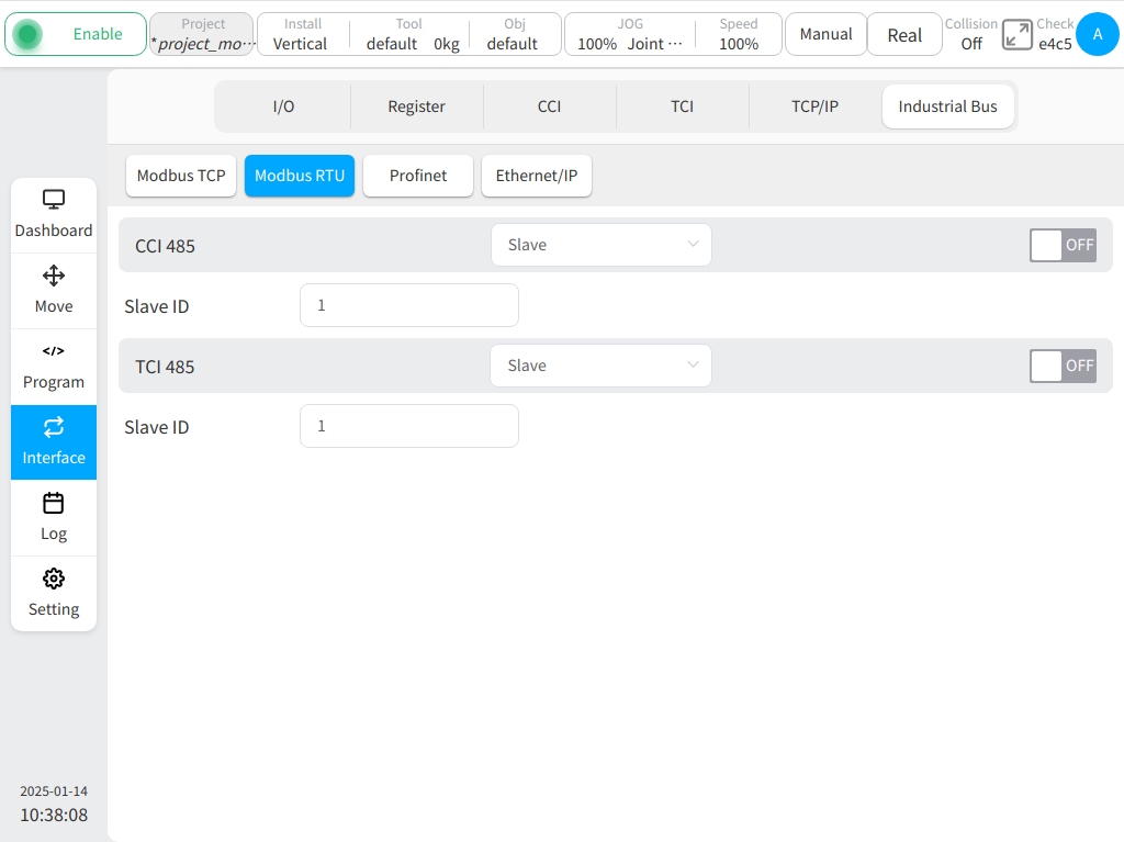
Using Modbus RTU Function, robot system can work as a Modbus Master through controller 485 interface or and robot tool 485 interface and connect to external Modbus Slave devices when robot is in power on status. It is able to read and write the register of Modbus Slave through Modbus address. All related operations such as add, delete, edit and etc to the Modbus nodes are completely as same as those for Modbus TCP Function.
Note
After controller 485 interface or robot tool 485 interface is configured and enabled with the Modbus mode, it is not able to operate the coresponding 485 interface directly through the related scripts and functions, It is only feasible to do the read and write operation to the Modbus register through target Modbus address by using Modbus related scripts and functions.
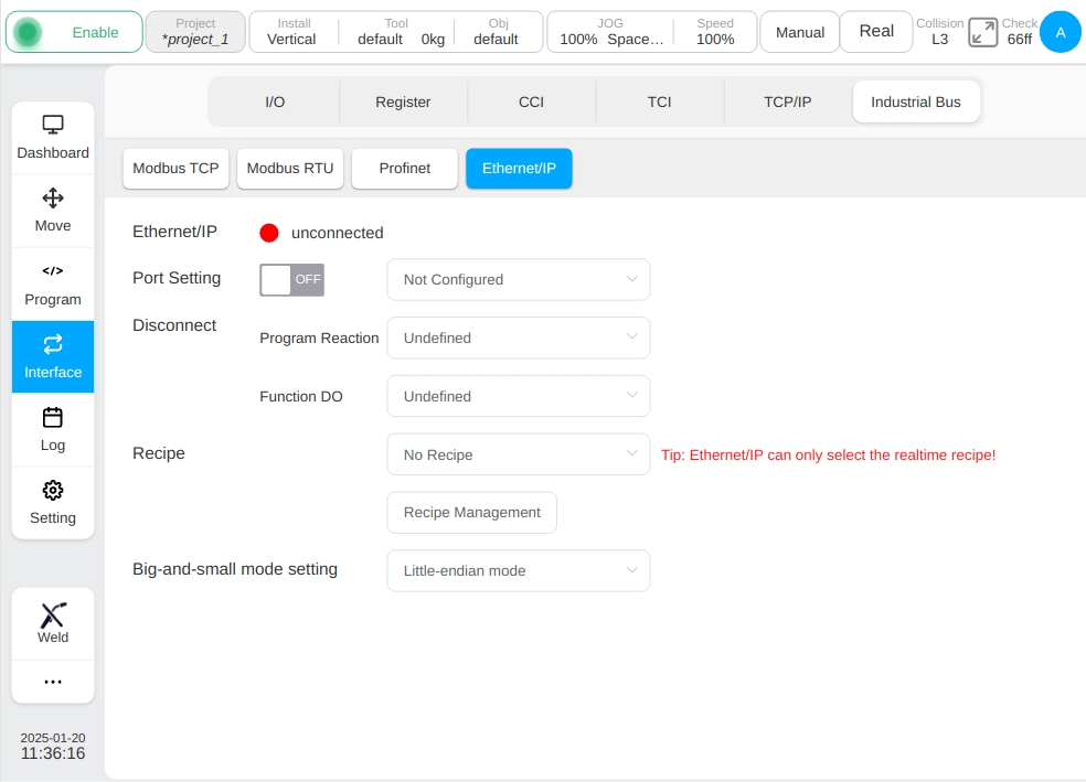
The Profinet and Ethernet/IP subtabs are mainly used to display the connection status, port settings and disconnection processing configuration, including the program response action and the corresponding configuration of the function output IO. Port Settings include whether to enable and configure the corresponding port name. Program response selector options are: undefined, paused program, stop program; The function DO Output selector drop-down options include: undefined and undefined output signal names in the function output signal in the I/O subpage. The DO function configured for Profinet and Ethernet/IP disconnect on each sub-label page is synchronized with the function output configuration on the I/O sub-page.
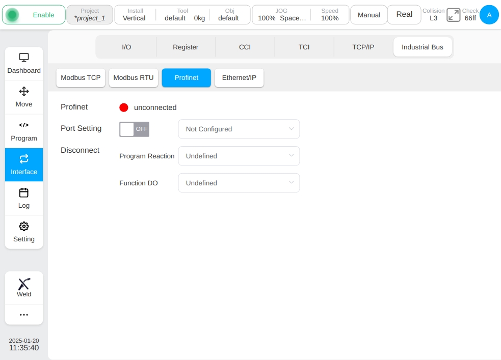
In addition, the Ethernet/IP sub-tab can also be used for recipe configuration and recipe management, and big-and-small mode settings.
Note
Note: Ethernet/IP only allows to select realtime recipes!