


Move Page#
Click the ‘Move’ button in the navigation bar to enter the move page, as shown in the figure.
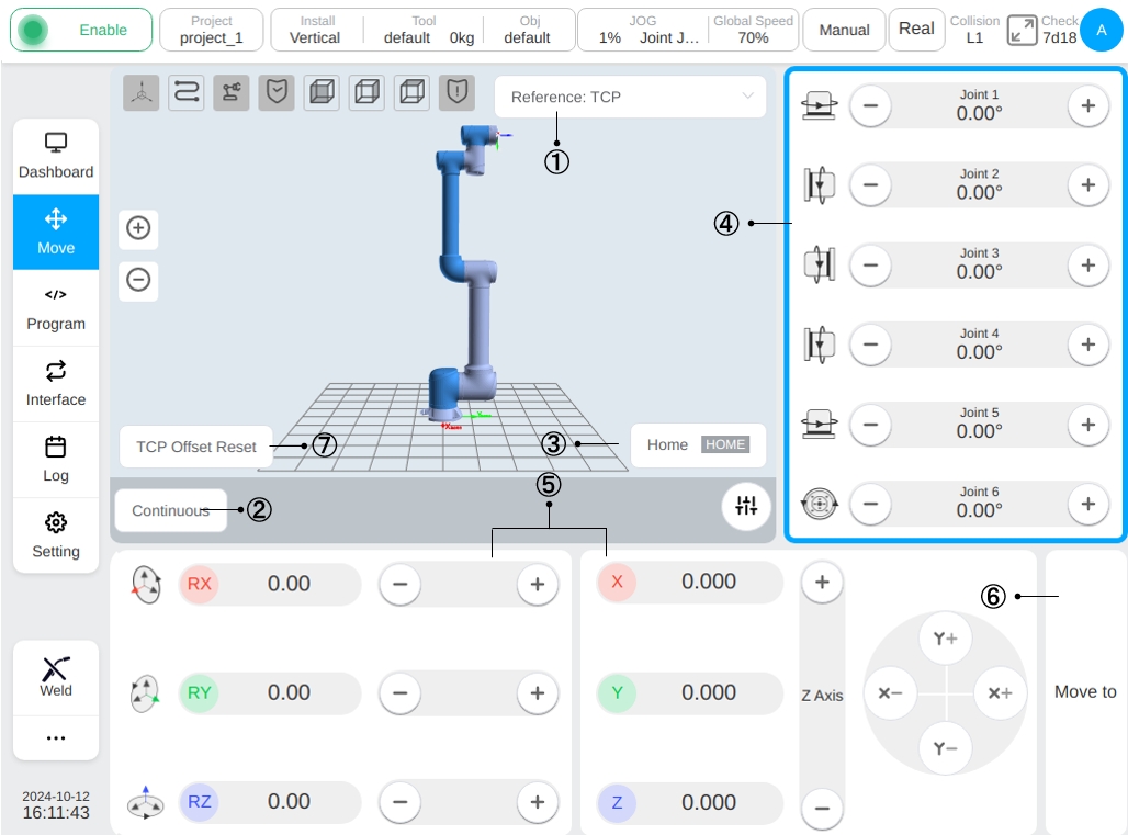
The 3D simulation model is displayed on the top left of the page, click ① Selector, the user can select the coordinate system used by the current robot and the reference coordinate system for manual operation of the robot, by default, the world coordinate system will be used (the same as the base coordinate system in this system), which means that the base of the robot is used as the coordinate base point. It is also allowed to select the tool coordinate system and the workpiece coordinate system. The tool coordinate system indicates that the end point of the end tool is the coordinate base point and the workpiece coordinate system is freely set by the user. After switching the reference coordinate system, the positional attitude data of the robot in Cartesian coordinates displayed on the interface will be changed accordingly.
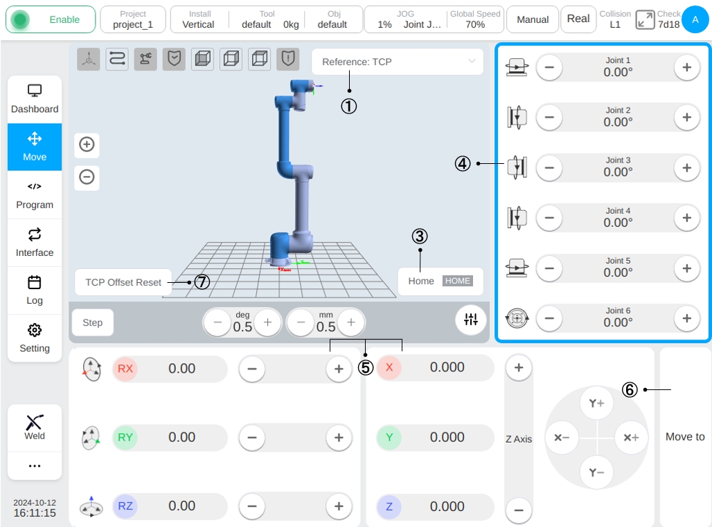
Icon ② is the button that allows the user to switch modes while the mode displayed on the button is the currently selected movement mode. Click the ‘Continuous Mode’ button to switch to ‘Step Mode’ and the interface will display the adjustment buttons for step angle and step distance and the data display box. The default values of step angle and step distance for user-defined movement are 0.5deg and 0.5mm, the minimum allowable settings are 0.1deg and 0.1mm and the maximum allowable settings are 5deg and 5mm to adjust the stepping angle and stepping distance.
Icon ③ is the ‘Press and Hold to Reset’ button. By pressing and holding this button, the robot will move to the set HOME point, releaseing the button will cause stop moving. The default home point is 0° for each joint and the robot is in an upright position. When the robot moves to the ‘HOME’button in the word background of ‘Hold Down and Return’ changing to green, indicating that the robot has reached the HOME location, as shown in the figure.
Area ④ is the area where the manually operated robot joints move. When the user click anywhere in this area, the area will display a blue border, representing currently is under manually robot joint movement operation. Pressing and holding the left arrow or right arrow button of a joint to move the joint in the forward or reverse direction, releasing the button to stop the joint from moving. Users can also move the joints by pressing and holding the ‘+’ and ‘-’ buttons on the right side of the teach pendant, which correspond to joints 1 to 6 from top to bottom.
Area ⑤ is the area where the end of the manually operated robot is moving in the Cartesian coordinate system. Again, when clicking anywhere in this area, the area will display a blue border, representing the current movement of the manually operated end of the robot. Pressing and holding the X, Y, and Z axis buttons changes the robot’s position in the Cartesian coordinate system by pressing and holding the RX, RY, and RZ buttons to change the robot’s attitude in the Cartesian coordinate system and releasing the corresponding buttons stops the robot from moving. Similarly, the user can change the robot’s positional attitude by pressing and holding the ‘+’ and ‘-’ buttons on the right hand side of the teach pendant. The buttons correspond to the six directions of movement, X, Y, Z, RX, RY, and RZ, respectively, from top to bottom.
Caution
When using the physical button Jog robot on the teach pendant, it is essential to confirm whether joint space motion or Cartesian space motion is controlled according to the current active state( blue border).
Icon ⑥ is the switch button for users to manually input the joint angle or pose value and hold down the button to move the robot. Clicking the ‘Move to’ button, the input box for inputting the joint angle and pose value will be displayed in area ④ and area ⑤ respectively, and a grayed-out robot model of the target point location will be displayed in the 3D model area. The 3D model area will display a grayed-out robot model at the target point location, as shown in the figure:
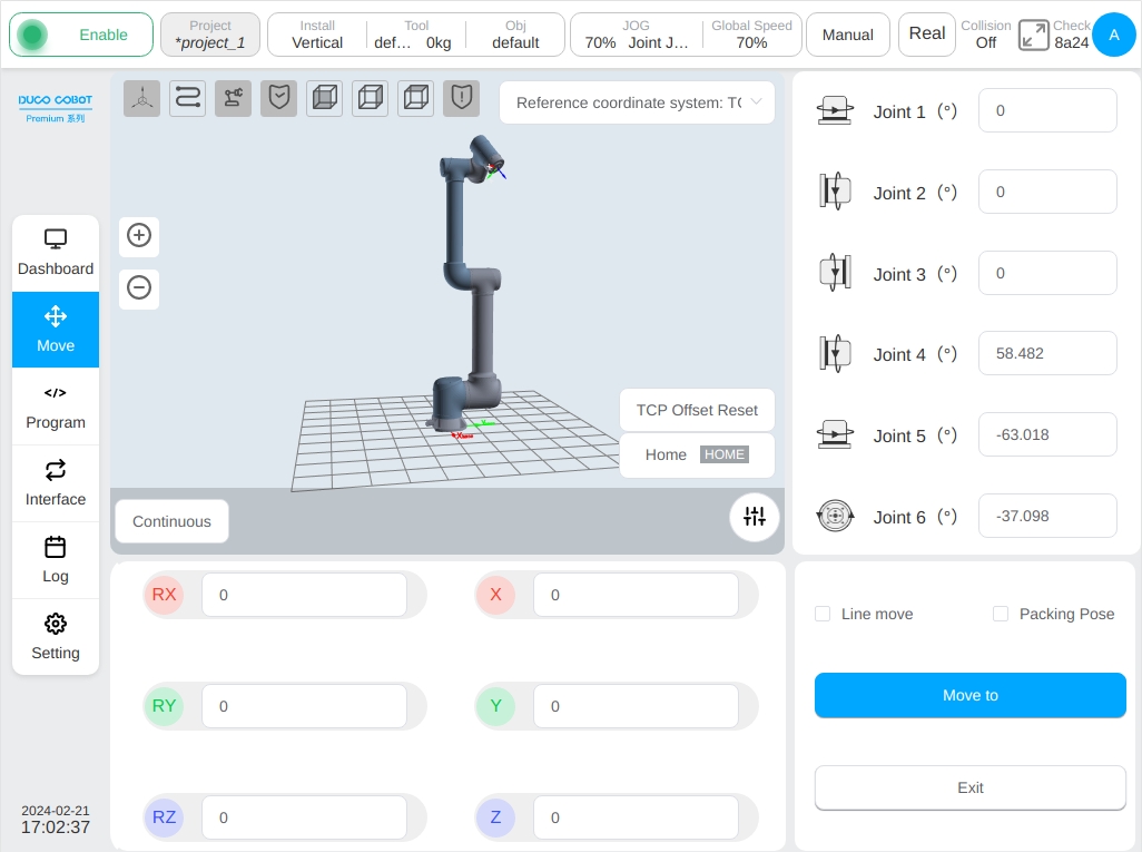
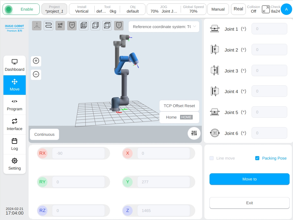
Click the input box of joint angle and position value to pop up the virtual numeric keypad, after inputting the target position data in the virtual numeric keypad, click the ‘Esc’ key to close the virtual numeric keyboard. Then, press and hold the ‘Move to’ button, the robot will move to the target position, releasing the button and the robot will stop moving. When the ‘Straight Move’ radio box is checked, showing the robot moves to the target position in a straight line; otherwise, it means the robot moves to the target position in a joint. When the ‘Packed Attitude’ radio box is checked, the ‘Linear Move’ radio box is disabled, the joint angle and Cartesian position attitude input boxes are disabled, and the ‘Linear Move’ radio box is disabled for the checked ‘Linear Move’ radio box. The ‘Linear Move’ radio box will be unchecked, and the joint angle and position attitude values will be shown as fixed values in the packing attitude, indicating that the robot will move to the packing position with the joints, and clicking the ‘Exit’ button will exit the interface of manually inputting the target position, and go back to the original moving interface. As shown in the figure:
Icon ⑦ is the ‘Tool Offset Reset’ button, which is displayed only when the reference coordinate system of the moving page is selected as the tool coordinate system. When the user clicks this button, the position at the moment of clicking will be used as the reference starting point, and the robot position will be displayed in real time in area ⑤ during robot movement with reference to the offset from the reference starting point at the time of clicking the button. The reference starting point for calculating the TCP offset is not updated until the user clicks the ‘Tool Offset Reset’ button again.