


Settings Page#
Click Settings in the navigation bar to enter the tool Settings subpage under the Settings page by default. Under the Settings page, there are 9 sub-pages: tool Settings, workpiece coordinate system, installation settings, system variables, safety settings (see chapter 5 for details), system events, other Settings, background scripts and plugins settings.

Tool Settings#
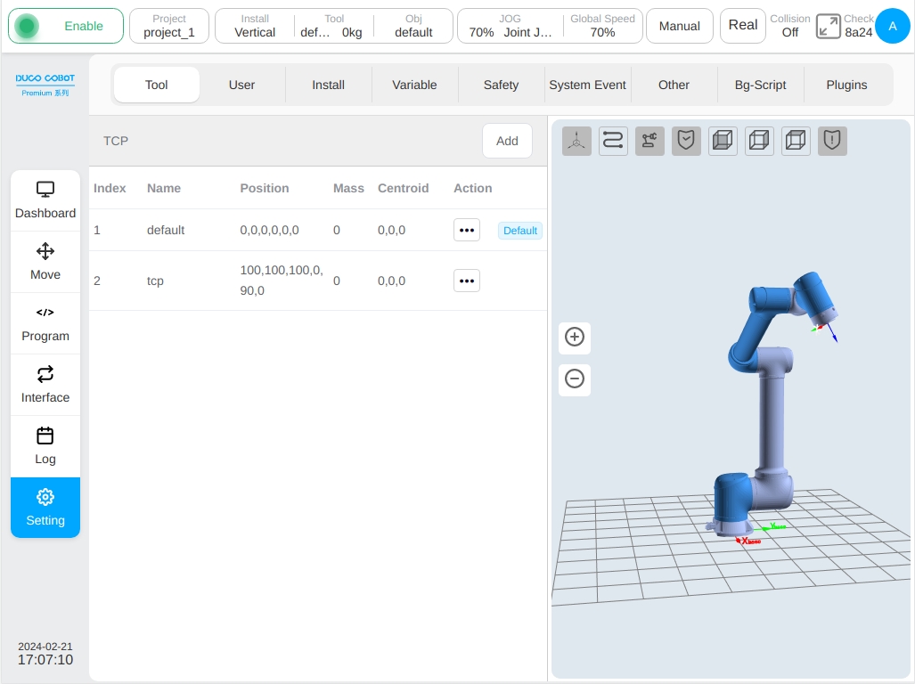
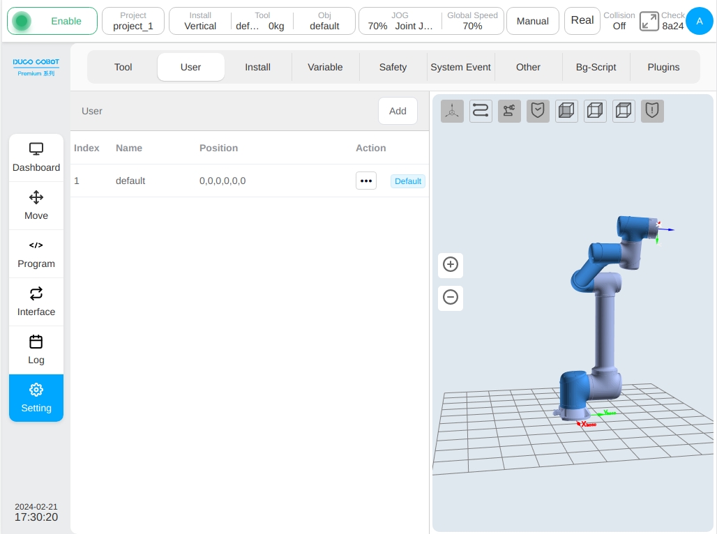
The left side of the tool setting subpage is the information about the set tool coordinate system. The tool coordinate system named default is the default tool coordinate system. On the right is a 3D model of the robot.
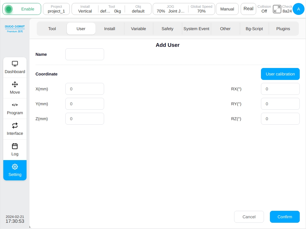
Click the ‘Add’ button, the window of new workpiece coordinate system will pop up. The user can set the name of the workpiece coordinate system, the position of the workpiece coordinate system relative to the world coordinate system (X, Y, Z), and the corresponding positive direction of the X, Y, Z axes (RX, RY, RZ). After setting the workpiece coordinate system, the corresponding workpiece coordinate system is displayed on the workpiece setting page. Multiple workpiece coordinate system settings can be saved.
After setting the tool coordinate system, the corresponding tool coordinate system will be displayed on the tool setting page, as shown in the tool coordinate system tcp1. Multiple tool coordinate system settings can be saved.
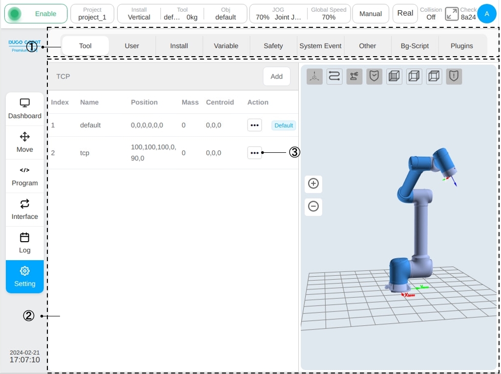
Click the operation column icon  for each row of tool coordinate system to display the coordinate system box. When the corresponding tool coordinate system is set to the default coordinate system, the word ‘Default’ will be displayed after icon .
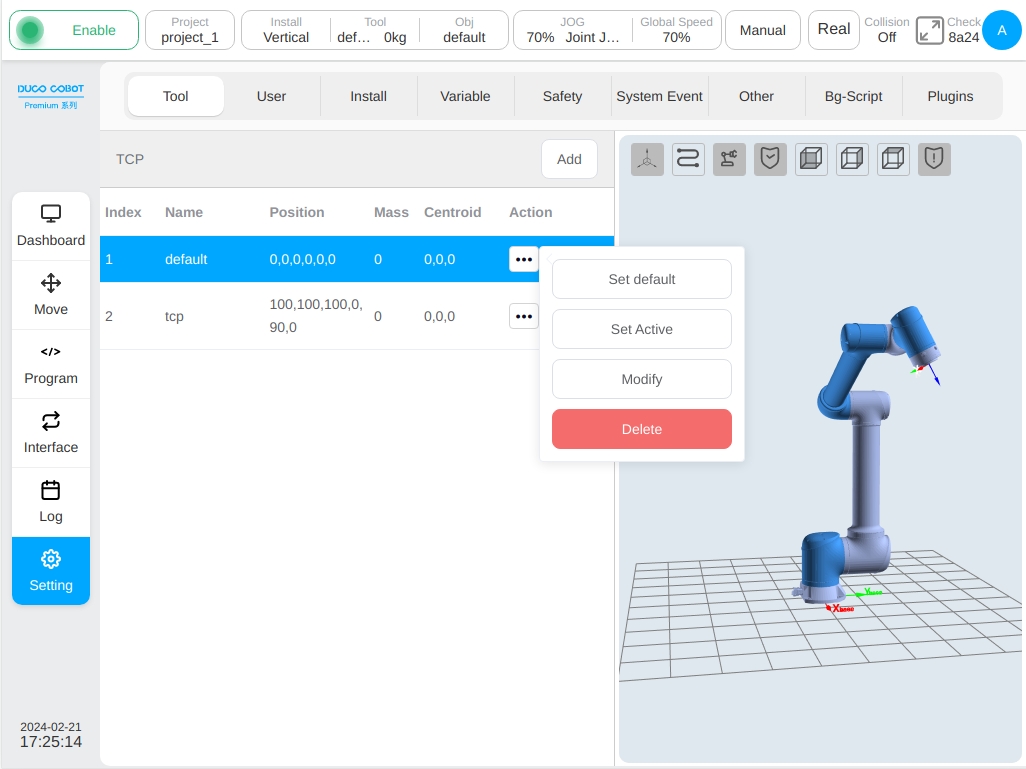
When the corresponding tool coordinate system is set to the current coordinate system, the name of the coordinate system and the quality of the tool are displayed in the tool box of the status bar. Click the ‘Modify’ button to modify the parameters related to the tool coordinate system, or click the ‘Delete’ button to delete the tool coordinate system. Note: The default or current tool coordinate system cannot be deleted!
When the user select a different tool coordinate system, the 3D model area displays the position of that coordinate system accordingly. Where, red represents the X-axis, green represents the Y-axis and blue represents the Z-axis.
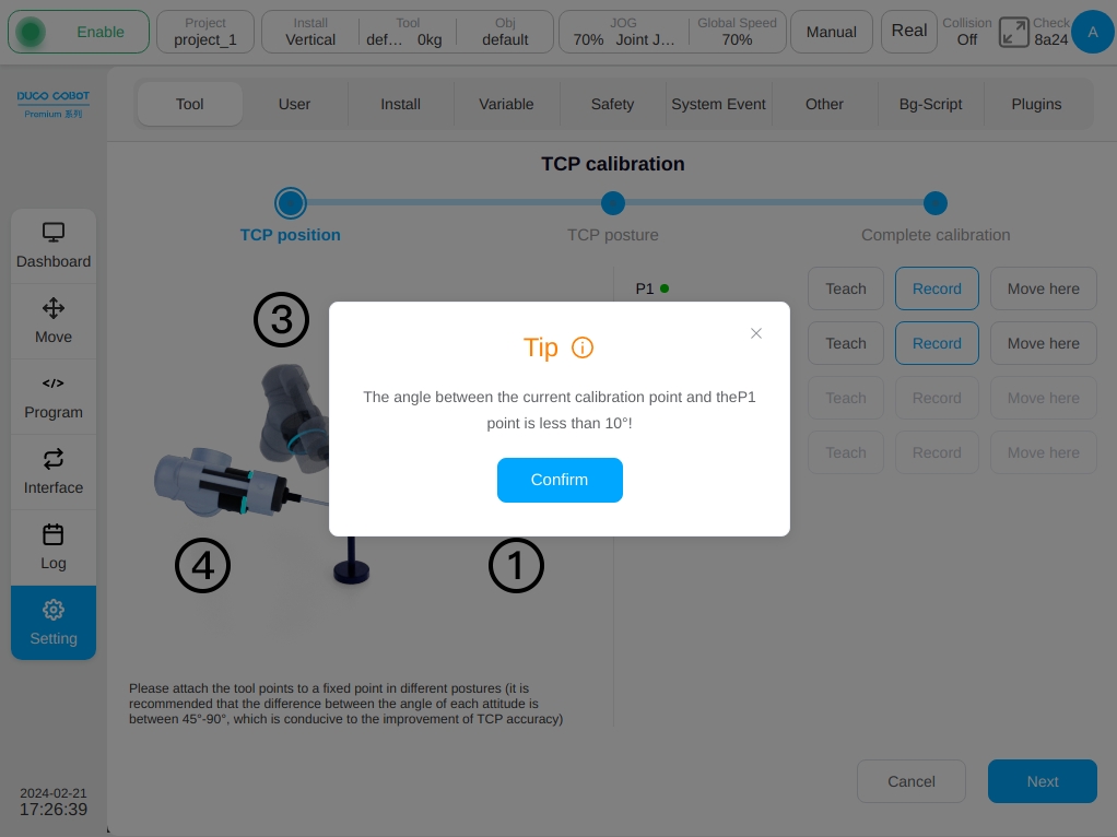
In addition to manually setting the tool coordinate system, the tool coordinate can also be calibrated. There are two ways to calibrate the tool coordinate system: 4-point calibration (custom) and 6-point calibration (two-point setting). In the Add Tool window, click the ‘TCP Calibration’ button to enter the TCP position calibration phase of the TCP calibration process. The following information is displayed:
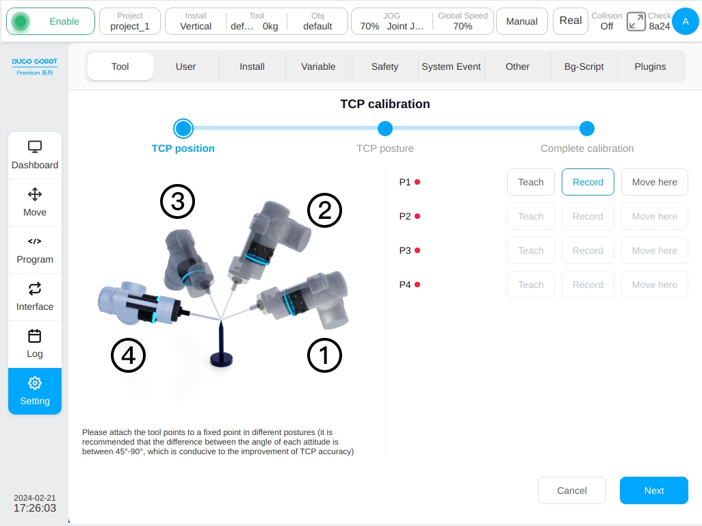
First of all, it is necessary to attach the tool point to the fixed point of the calibration needle in different posture, that is, to teach the P1-P4 points well, and it is recommended that the posture Angle change between the points should be between 45° and 90°, which is conducive to improving the accuracy of TCP calibration. Take point P1 as an example, click the ‘Teach’ button at point P1, and the interface will jump to the mobile page. After the mobile robot reaches the target point, click the ‘Record Current Position’ button, the interface will jump back to the interface of the current teaching mark point. After teaching a mark point, the red dot behind the corresponding mark point will turn green. The user can also move the robot directly to the target point through the physical button of teach pendant and click the ‘Record Current Point’ button directly. During the teaching process, if the current teaching point does not meet the restrictions, the following message will be displayed:
After teaching all P1-P4 points in turn, click the ‘Next’ button at the lower right corner of the page to enter the TCP posture calibration stage. TCP posture calibration has two forms: custom and two-point Settings, the default is custom, as shown below:
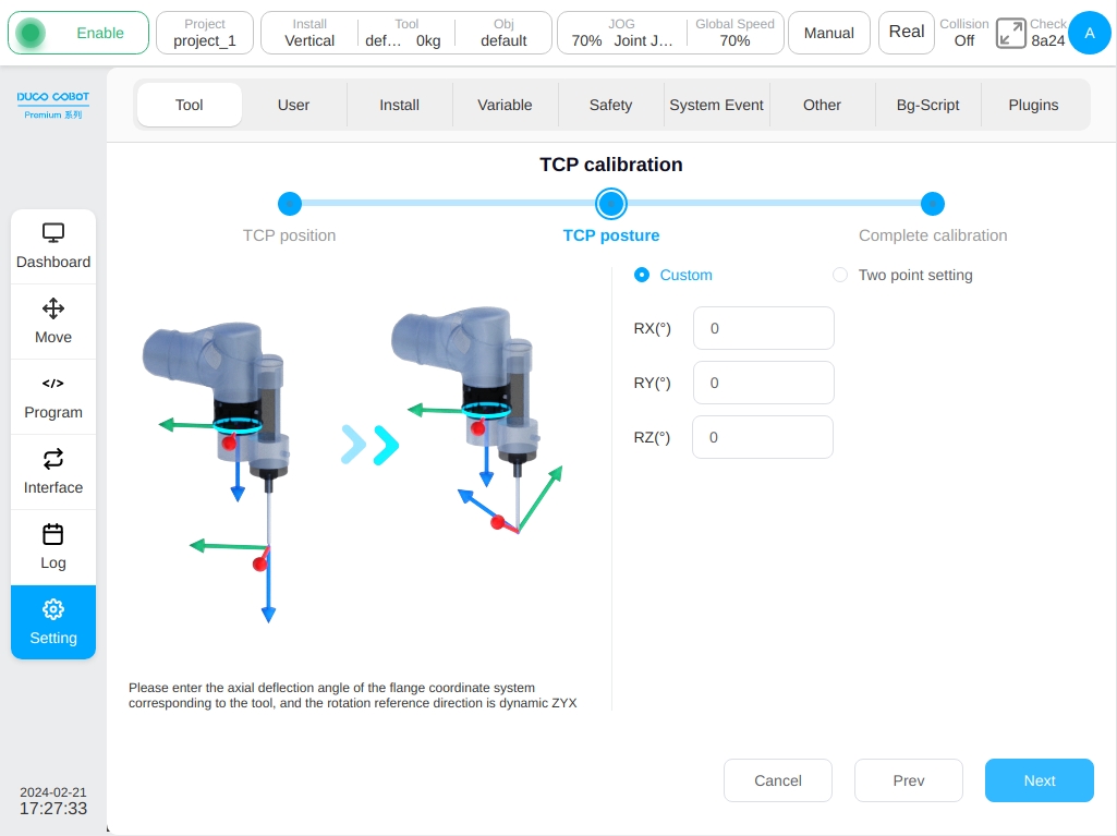
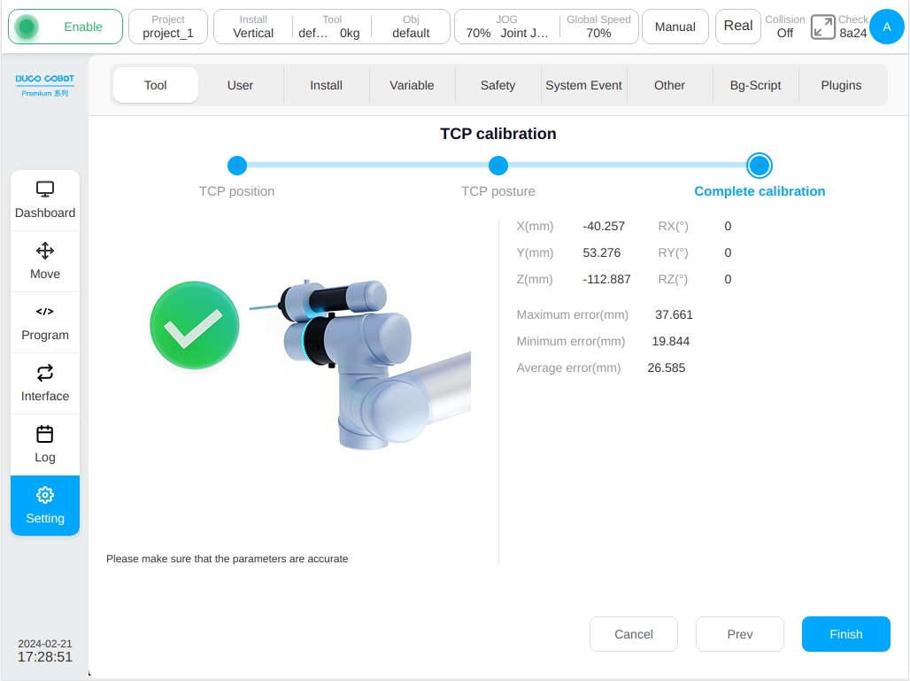
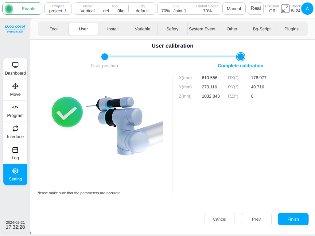
After setting the axial deflection Angle of the tool corresponding to the flange coordinate system, click the ‘Next’ button to enter the calibration completion stage, and the calibration results and error information will be displayed as shown below. The user can judge the quality of the calibration through the error information, so as to decide whether the coordinate system needs to be loaded. If the user needs to load this coordinate system, click the Confirm’ button, otherwise click the ‘Cancel’ button, or click the ‘Previous’ button to return to the teaching point again.
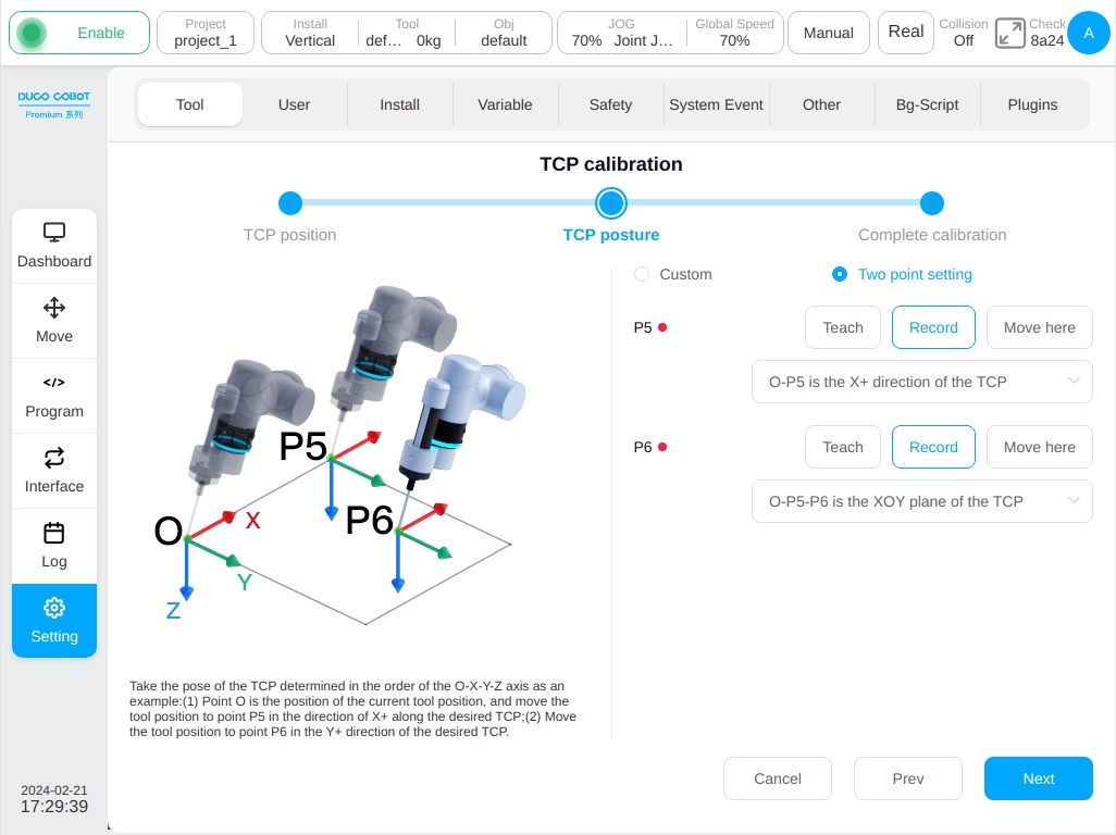
When the ‘Two-point Setting’ is selected in the TCP posture calibration phase, the following figure is displayed: The options of the P5 point are O-P5 as the tool coordinate X+ direction /Y + direction/Z+ direction, the corresponding options of the P6 point are O-P5-P6 as the tool coordinate XOY plane /XOZ plane, O-P5-P6 as the tool coordinate XOY plane /YOZ plane, and O-P5-P6 as the tool coordinate XOZ plane /YOZ plane. For example, to determine the posture of the tool coordinate system according to the O-X-Y-Z axis: Point O is the position of the current tool position, first move the tool position in the direction of the desired tool coordinate system X+ to point P5, and then move the tool position in the direction of the desired tool coordinate system Y+ to point P6.
After setting the instruction P5 and P6, click the ‘Next’ button to enter the calibration completion stage and the calibration result and error information will be displayed. The user can judge the quality of the calibration through the error information, so as to decide whether the coordinate system needs to be loaded. If the user needs to load this coordinate system, click the ‘Confirm’ button, otherwise click the ‘Cancel’ button, or click the ‘Previous’ button to return to the teaching point again.
Workpiece Coordinate#
The offset of the workpiece coordinate relative to the world coordinate system can be set in the workpiece coordinate system setting. Similar to the tool setting page, the left side of the page is related information about the set workpiece coordinate system. The workpiece coordinate system named default is the system default workpiece coordinate system. On the right is a 3D model of the robot.
Click the ‘Add’ button, the new workpiece coordinate window will appear. The user can set the name of the workpiece coordinate system, the position of the workpiece coordinate system with respect to the world coordinate system X, Y, Z and the corresponding positive direction of the X, Y, and Z axes (RX, RY, RZ). After setting the workpiece coordinate system, the corresponding workpiece coordinate system will be displayed on the workpiece setup page. Multiple workpiece coordinate system settings can be saved.
Similarly, in addition to manually setting the workpiece coordinate system, the workpiece coordinate can also be calibrated. Click the ‘Workpiece Coordinate System Calibration’ button to enter the workpiece coordinate system position calibration phase of the workpiece coordinate system calibration process, which is displayed as follows:
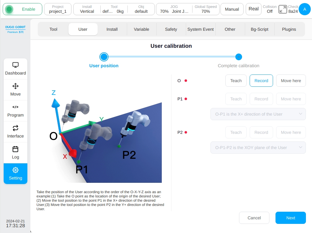
Set O point as the origin of the workpiece coordinate system, and P1 point can be selected as the tool coordinate system X+ direction/Y+ direction/Z+ direction. The options corresponding to point P2 are O-P1-P2 as the tool coordinate system XOY plane /XOZ plane, O-P1-P2 as the tool coordinate system XOY plane /YOZ plane, and O-P1-P2 as the tool coordinate system XOZ plane /YOZ plane. For example, to determine the posture of the tool coordinate system according to the O-X-Y-Z axis: Point O is the position of the current tool position, first move the tool position in the direction of the desired workpiece coordinate system X+ to point P1, and then move the tool position in the direction of the desired workpiece coordinate system Y+ to point P2.
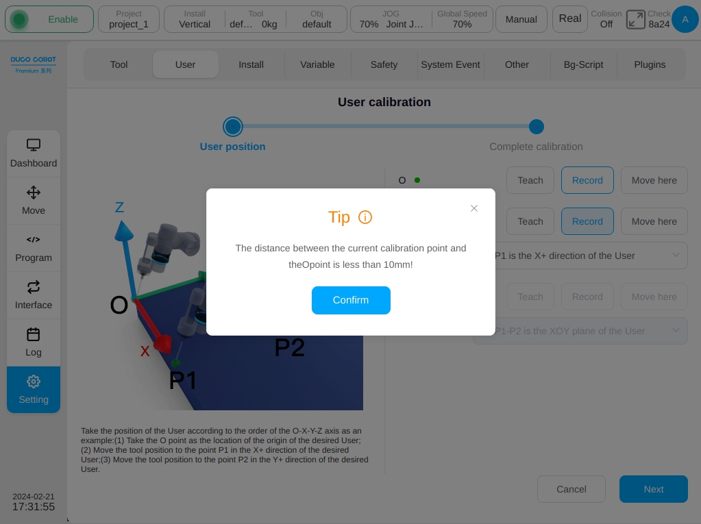
Take P1 as an example, click the ‘Teach’ button after P1, and the interface will jump to the mobile page. After the mobile robot reaches the target point, click the ‘Record Current Position’ button and the interface will jump back to the interface of the current teaching marker point. After teaching a marker point, the red dot behind the corresponding marker point will turn green. The user can also move the robot directly to the target point by pressing the physical button of teach pendant and click the ‘Record Current Point’ button directly. During the teaching process, if the current teaching point does not meet the restrictions, the following message will be displayed:
After setting the instruction O, P1 and P2, click the ‘Next’ button to enter the calibration completion stage as shown below, and the calibration result will be displayed. The user can judge the quality of the calibration through the error information, so as to decide whether the coordinate system needs to be loaded. If the user needs to load this coordinate system, click the ‘Confirm’ button, otherwise click the ‘Cancel’ button, or click the ‘Previous’ button to return to the teaching point again.
Installation Settings#
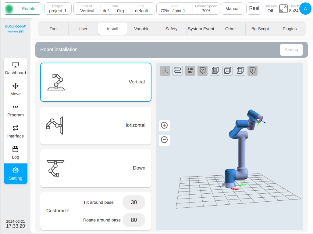
The Installation Settings sub-page is mainly for setting the installation direction of the robot, which can be set to any one of Vertical, Horizontal, Inverted and Customized. In the customization mode, the user can set the tilt angle of the robot around the base and the rotation angle of the robot around the base, and the setting range is -180°~180°. When switching the mounting method, the 3D model will also change the mounting direction. After setting the robot mounting direction, click the ‘Set’ button at the top right of the interface, and the mounting method will be displayed in the mounting box in the status bar.
System Variables#
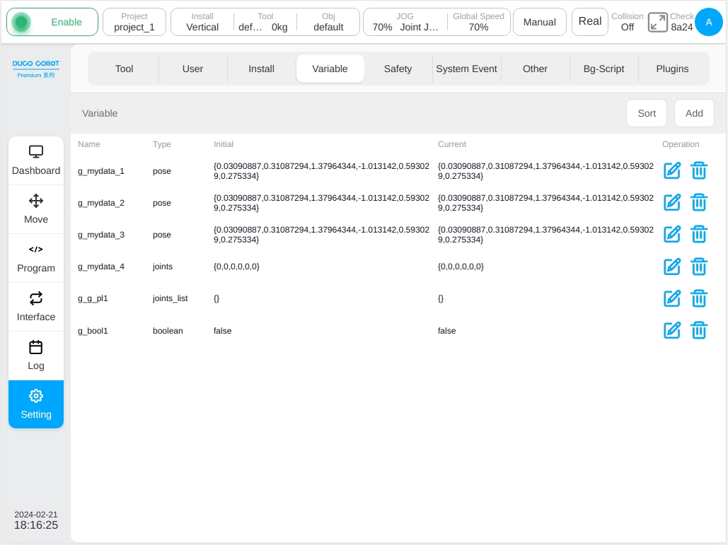
The Variable Setup sub-screen focuses on creating and displaying information about system variables. The information of system variables displayed are: name, type, initial value, current value and buttons to modify or delete each variable. Among them, there are 13 types of variables, which are boolean, number, string, num_list, pose, joints, pose_list, joints_list, timer, pose_speed, pose_acc, joint_speed and joint_acc. The initial and current values represent the initial value when the variable is defined and the process value during the application of the program, respectively.
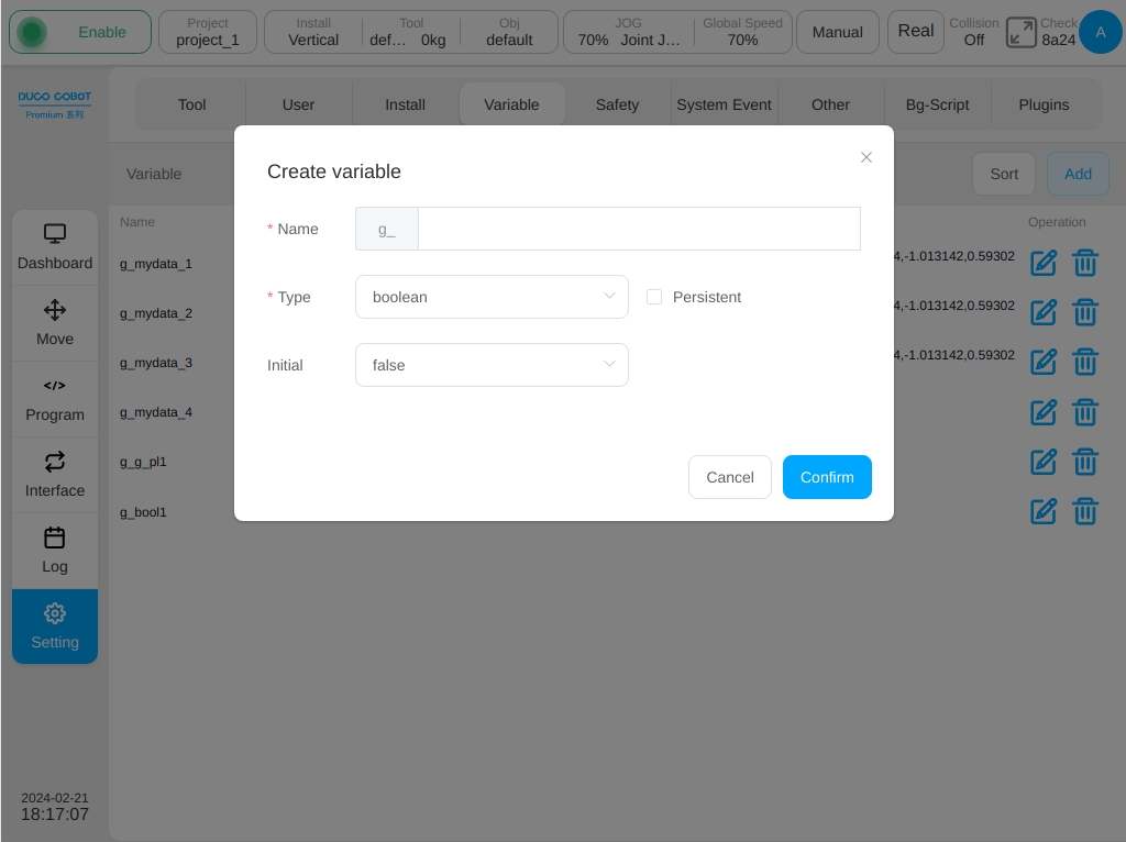
Click the ‘Add Variable’ button in the upper left corner of the interface and a window for creating a new variable is displayed. Enter the variable name, type, and initial value, and click the ‘OK’ button. Each variable name is marked with a g_, indicating that it is a global variable, with each variable type can be selected as a ‘Hold Variable’. If the ‘Retain Variable’ option box next to the variable type is selected for a newly created variable, a message is displayed before the variable name. For example, the added number variable aa is a hold-type variable. If it is set to a retained variable, the system saves the last value each time. Otherwise, the variable is initialized at its initial value.
The initial value of boolean type can be false and true;
The initial value of the number type is 0, and the variable value supports integers and decimals.
The initial value of the string type is empty;
The array type num_list is either an integer array or a floating point array wrapped in curly braces;
The pose type is a floating-point array of length 6 wrapped in curly braces;
The joints type is a floating point array of length 7;
The pose_list type is a two-dimensional array of floating-point arrays of length 6 wrapped in curly braces;
The joints_list type is a two-dimensional array of 7-length floating point arrays wrapped in curly braces.
The timing type timer is an integer array or floating point array wrapped in curly braces.
The variables of end velocity pose_speed type, end acceleration pose_acc type, joint angular velocity joint_speed type and joint angular acceleration joint_acc type are also number types in essence, supporting integers and decimals with each variable type has two unit displays. Each can input a unit variable value after the automatic filling of another unit conversion value. All variable types can be assigned manually. pose and joints variables can be initialized and edited through teaching methods, pose_list and joints_list variables can be directly added and joints_List variables can be added through teaching methods.
Click the ‘Select Position’ button, the interface will jump to the mobile interface, after teaching the desired posture, click the ‘Record Current Position’ button, the interface will return to the new variable window and record the teaching pose value to the corresponding initial position, there should be two units of mm/deg and m/rad display values.
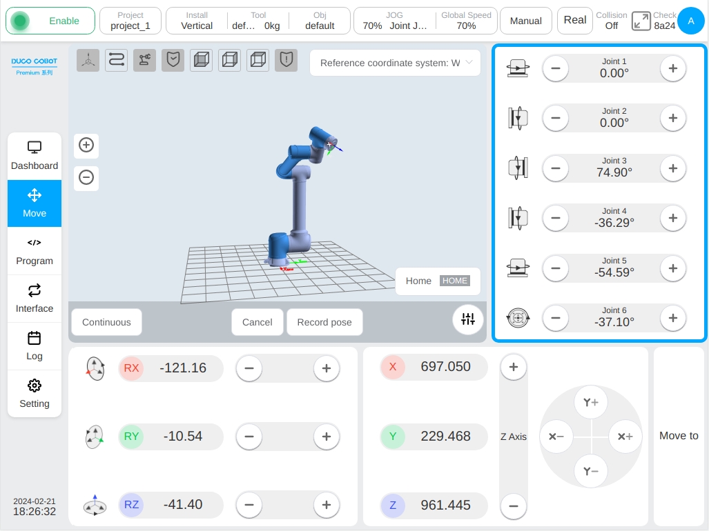
In addition to teaching initialization, the user can also click the initial value input box to manually initialize the assignment where joints type variable creation is similar to the pose type and is not covered here.
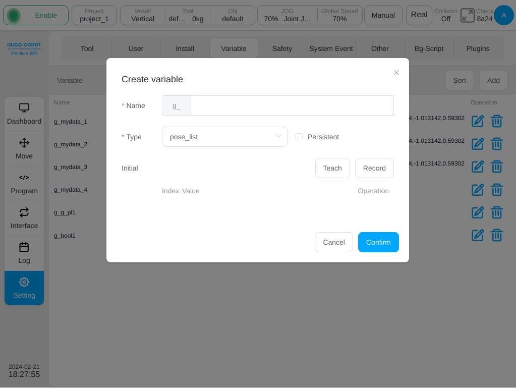
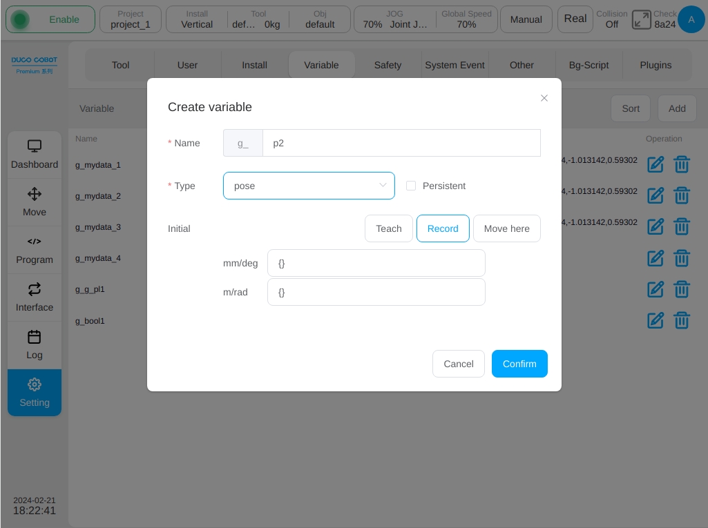
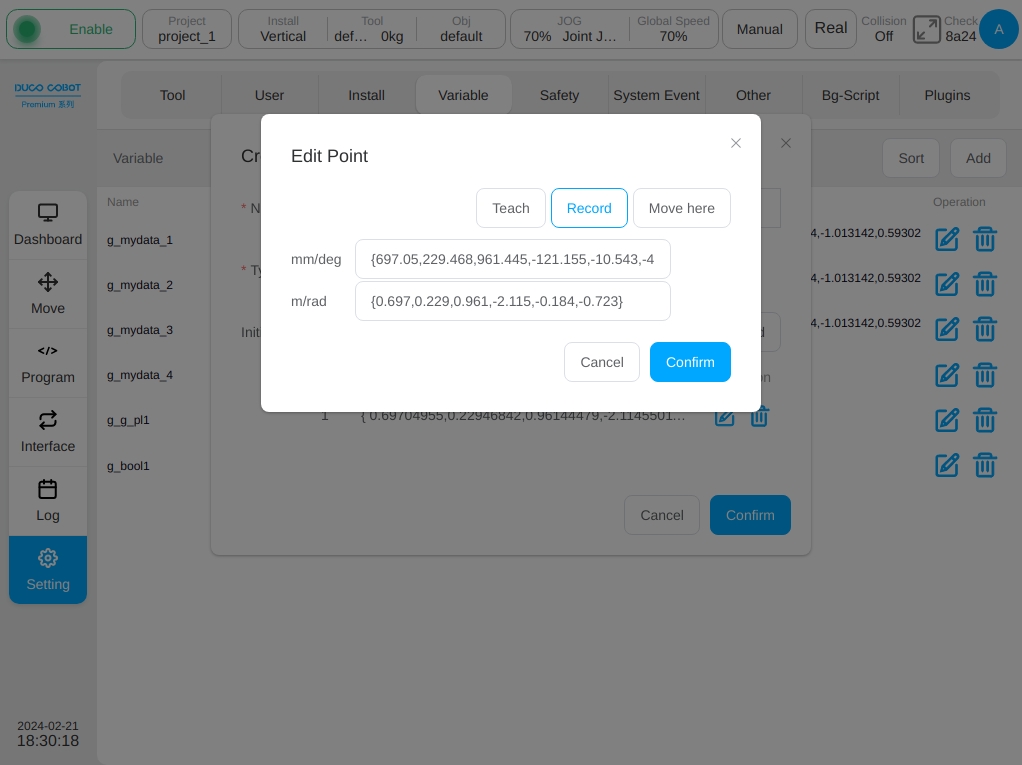
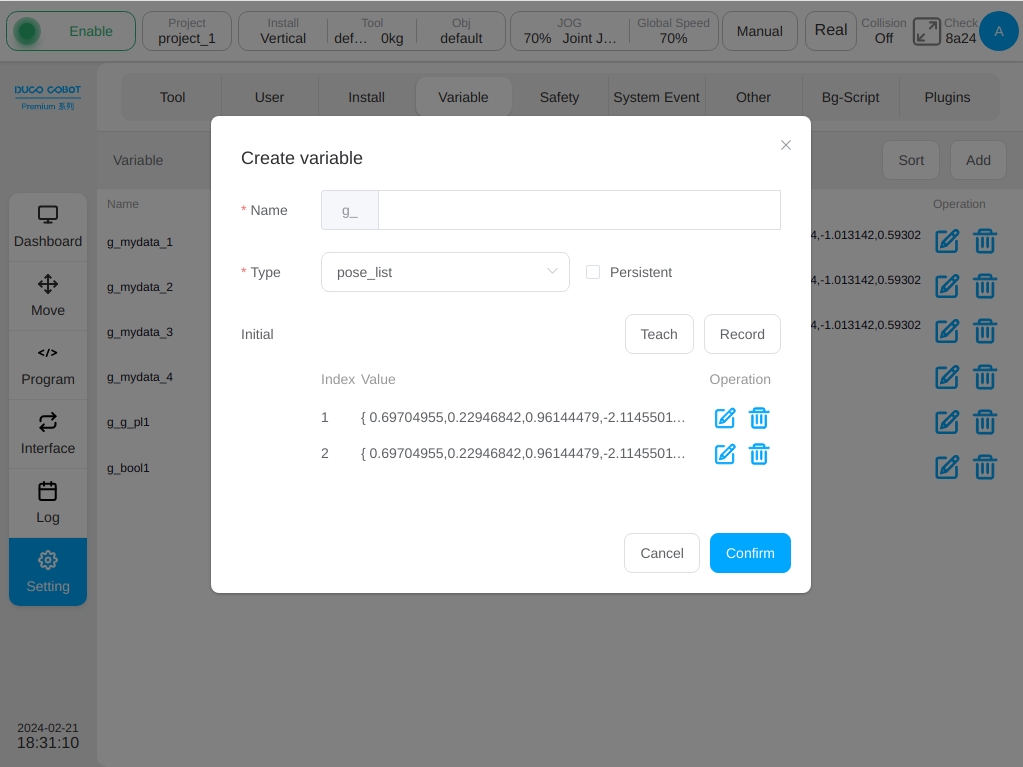
When creating pose_list variables, the initial value can be added in any way by the ‘Teach’ or ‘Record’. By clicking the ‘Record’ button, the serial number, value, and operation of the corresponding variable will be displayed at the bottom of the interface, and click icon  in the operation column will pop up the edit point window, the operation process is similar to the pose type variable teaching process, here is not repeated.
After selecting the pose position, the interface is as follows:
The joints_list variable creation process is similar to the pose_list type and is not covered here.
When modifying a variable, click icon corresponding to the variable row, a window for editing variables will pop up. The variable type is not modifiable, only the initial value and whether it is a hold-type variable can be modified. To delete a variable, click icon  corresponding to the variable row.

System Events#
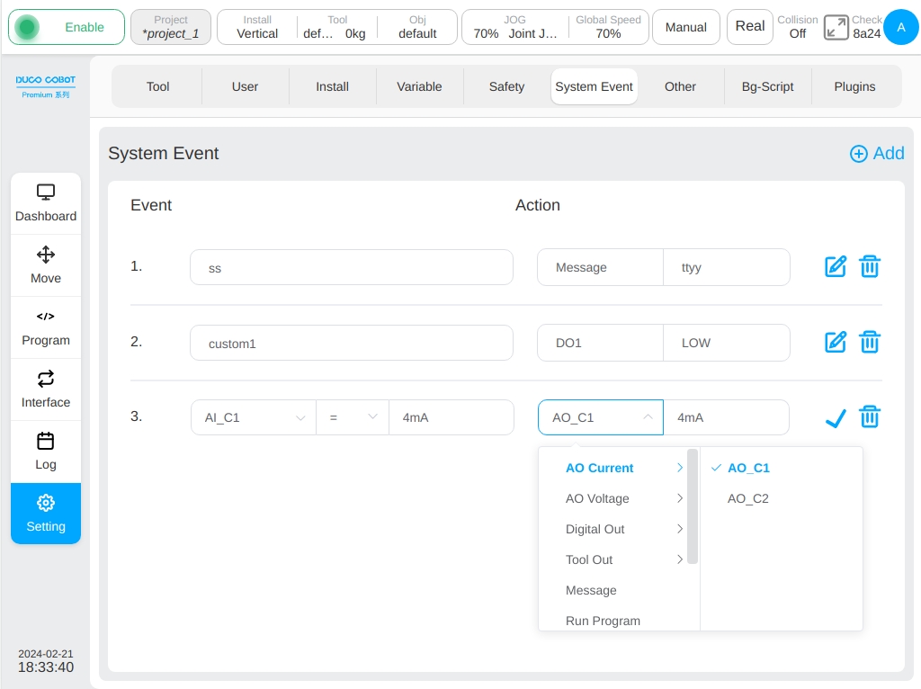
The System Events sub-page is mainly used to add additional general event functionality to the system, allowing the user to customize the event response when certain events occur. Currently, there are 9 types of events: Analog Current Input, Analog Voltage Input, Program Status, Register Bool Input, Register Word Input, Register Float Input, End Speed, Joint Torque, and Custom Event; and 9 types of responses: Analog Current Output, Analog Voltage Output, Generic Output, Tool Output, Popup Box, Run Program, Register Bool Output, Register Word Output, and Register Float Output. The response types are: analog current output, analog voltage output, general-purpose output, tool output, pop-up box, run program, register Bool output, register Word output and register Float output.
Note
The event is always triggered by the side. If the event triggering conditions are met, the event are will not trigger immediately after the setting. The event will be triggered next time.
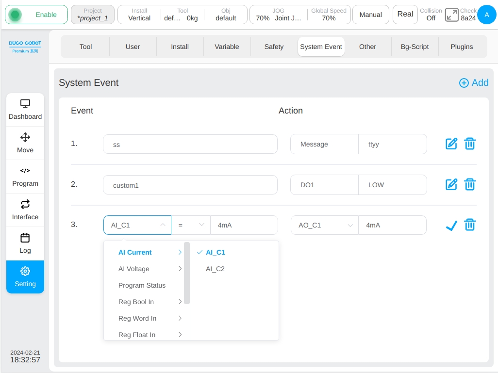
Click the ‘Add Event’ button in the upper right corner of the page to add an event response. The default event type is analog current input, the event condition is ‘=’ and the value is 4mA. The default response type is Analog current output, and the value is 4mA. Click icon next to each event response to enter the editing state, the user can edit each event response and then click icon  .The icon can remove the added event response.
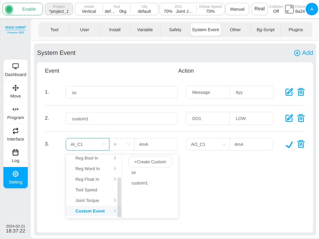
For a custom event, if no option is available in the list on the right of the custom event option, the user can click the ‘New Custom Event’ button in the list on the right of the custom event option to create a custom event. Click the ‘New Custom Event’ button, the virtual keyboard is displayed, prompting to enter a custom event name.
After the user enters the customized event name (such as custom1), an event response is added on the interface, as shown in the following figure:
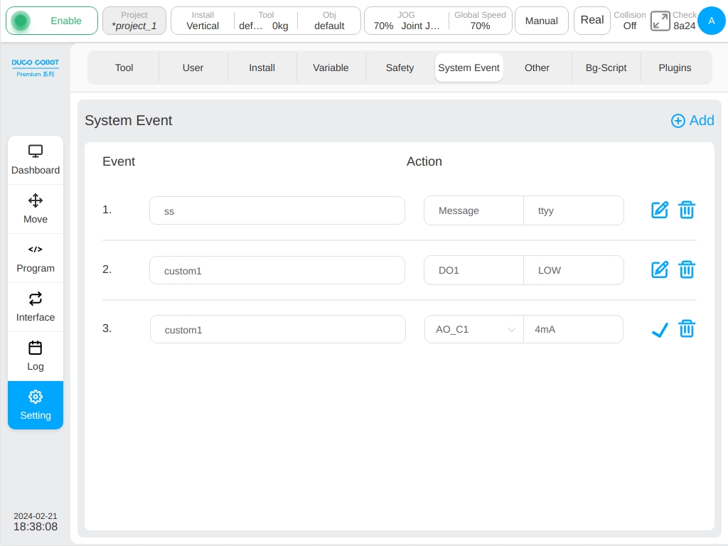
The newly created custom event is displayed in the Custom event options list with one custom event can correspond to multiple responses. In addition, if all event responses containing the same user-defined event are deleted, the user-defined event is also deleted. That is, the user-defined event is not available in the user-defined event option list.
Other Settings#
The ‘Other Settings’ sub-page focuses on Startup Settings, Edit HOME Points, Collision Settings (for Safety2 this setting was moved into Safety Settings), Force Sensor Settings, End Settings and Model Import Settings. On the left side of the screen are the navigation tabs and on the right side is the content area for the corresponding tabs. By default, the page displays the startup settings.
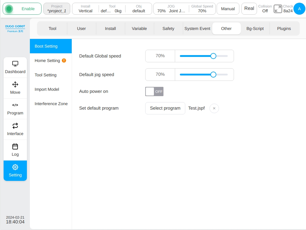
Boot Settings
Click the ‘Startup Settings’ TAB to set the default global speed, default jog speed, whether to log in automatically and set the default program.
Adjust the default global speed slider on the right, the user can set the default global speed of the robot;
By adjusting the default jog speed, the right slider can set the default jog speed of the robot;
The switch on the right button of ‘Robot Power on’ can be used to switch whether the robot is automatically powered on.
Click the ‘Select Program’ button, the program list window will pop up.
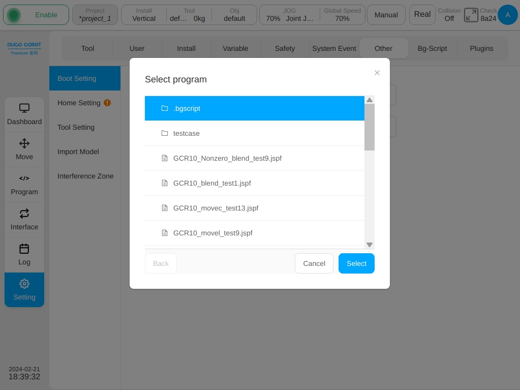
After selecting the program, click the ‘Select’ button. After setting the default program, the ‘Select Program’ button will display the name of the default program and the cross icon to cancel the default program.
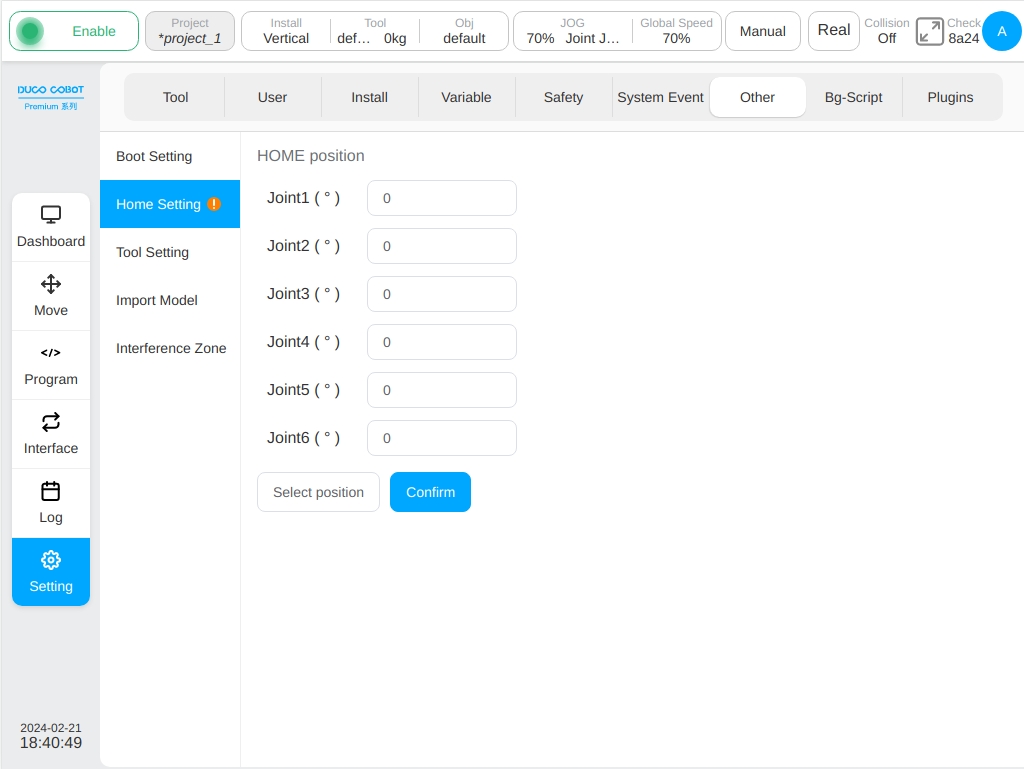
Home Settings
The angle value of each joint is displayed in the HOME position at the upper part of the interface. The user can manually enter the joint angle by clicking each joint input box, or by clicking the ‘Select HOME Position’ button to jump to the mobile interface for teaching Settings. Similar to the above process of creating pose variables, after showing the position, jump back to the current interface and click the ‘OK’ button to make the settings take effect.
Note
For J9/J9-ZII control cabinets, after selecting the “HOME” position, synchronize it to the safety controller. For details, read Safety
Collision Detection Settings
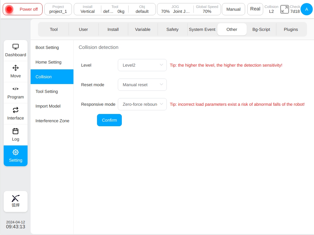
Collision detection settings for DC30 control cabinet, configure in other settings; For J9/J9-ZII control cabinets, configure in safety settings (see Section 6.2 for details). The collision detection area can set the collision detection level 、reset mode and responsive mode. The collision detection level is divided into: Off, level 1, level 2, level 3, level 4, and level 5. The higher the level, the higher the sensitivity of the collision detection. There are two collision detection reset modes: manual reset and automatic reset. There are three types of collision detection responsive modes: protective stop, safe emergency stop and zero-force rebound, among which, when the “zero-force rebound” option is selected, the prompt “Tip: incorrect load parameters exist a risk of abnormal falls of the robot!”. After configuring the collision detection level, reset mode , and responsive mode, the user can click the ‘OK’ button. When the collision detection response mode is configured as zero-force rebound mode, the robot will adapt to the collision external force within 1 second of detecting the collision and produce a rebound motion until it is no longer in contact with the external object where the collision occurred or the contact force is extremely small.
Tool Setting
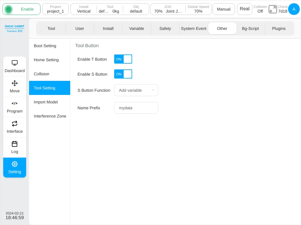
Set the ‘T’ and ‘S’ buttons at the end. The user can choose whether to enable the ‘T’ and ‘S’ buttons. Select the ‘Enable T’ button which has the function of holding down robot. The ‘S’ button is enabled to set the ‘S’ button function which has three functions: Add variable, add motion instruction, add variable and motion instruction. When the user select the ‘S’ button to add variables or add variables and motion commands, it also requires configured variable name prefixes. The default value is mydata. After global variables are recorded, their official names are g_mydata_1 and g_mydata_2. Each time a variable is added, the maximum value of the variable name suffix is checked. On this basis, the count is added.
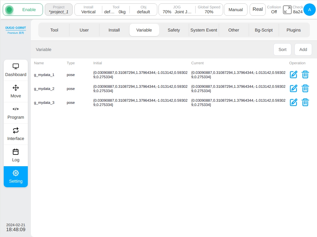
Under the premise of enabling the ‘S’ button , when the function of the ‘S’ button is configured to add variables, the variable name prefix uses the default value mydata. Click the trigger ‘S’ button, a new pose global variable will be added to the variable setting page. If the ‘S’ button is triggered three times a single time, three pose variables will be added to the variable setting page. The variable names are g_mydata_1, g_mydata_2, and g_mydata_3 in sequence, as shown in the figure below:
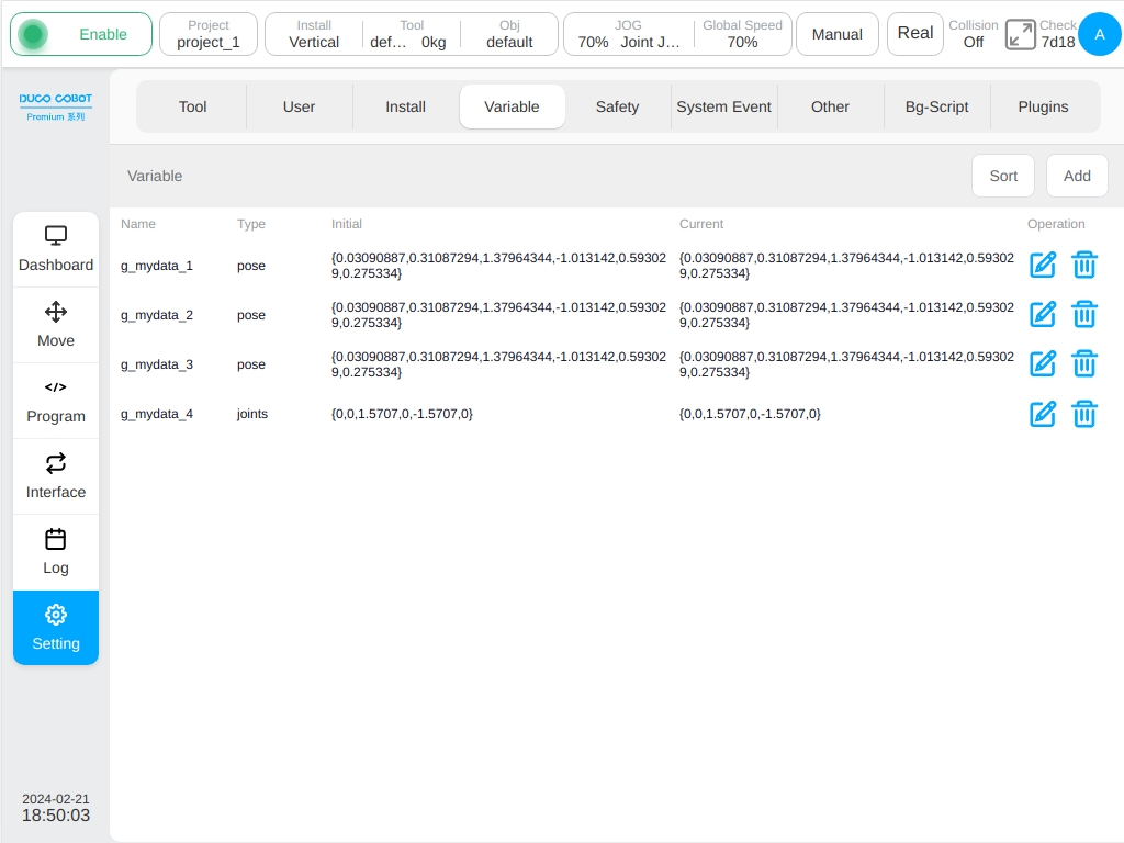
Long press the trigger ‘S’ button, and a new global variable of joints will be added to the variable setting page. For example, long press and trigger S button once, and another variable of joints will be added to the variable setting page, as shown in the figure:
When the function of ‘S’ button is configured to add motion instructions, click the trigger ‘S’ button to add a new MoveL instruction to the program page under the conditions of adding instructions (for example, it must be in the program editing state), and the Cartesian pose of the robot when the ‘S’ button is triggered corresponds to the X/Y/Z/RX/RY/RZ input box recorded in the MoveL instruction parameter page. When long press the trigger the ‘S’ button (more than 2 seconds), the newly added a MoveJ instruction program page trigger button moment robot ‘S’ each joint Angle corresponding to the record in the parameters page Joint1 MoveJ instructions/Joint2 / Joint3 Joint4 Joint5 / Joint6 input box.
When the function of ‘S’ button is configured to add variables and motion instructions, click the trigger ‘S’ button. In addition to adding a new global variable of pose type to the variable setting page, this variable records the Cartesian pose of the robot when the ‘S ‘button is triggered and a new MoveL instruction is added to the program page when the conditions of adding instructions are met. The newly added MoveL instruction is set to a variable form, the variable has been selected by default as the newly added pose global variable; After long pressing the trigger ‘S’ button, a new global variable of joints was added to the variable setting page, which recorded the angle of each joint of the robot when the ‘S’ button was triggered. A new MoveJ instruction was added to the program page when the conditions of adding instructions were met, and the newly added MoveJ instruction was set as a variable. The variables have been selected by default as global variables of the newly added joints type.
The above addition of motion instructions is valid only when the program page instruction node is under the Move node and the newly added MoveL instruction coordinate system is in use when the ‘S’ button is triggered with the parent node coordinate system option is not checked by default.
When the program page instruction node is in Spline, the ‘S’ button adds motion instructions in a way that adds waypoints to Spline.
Model Import Settings
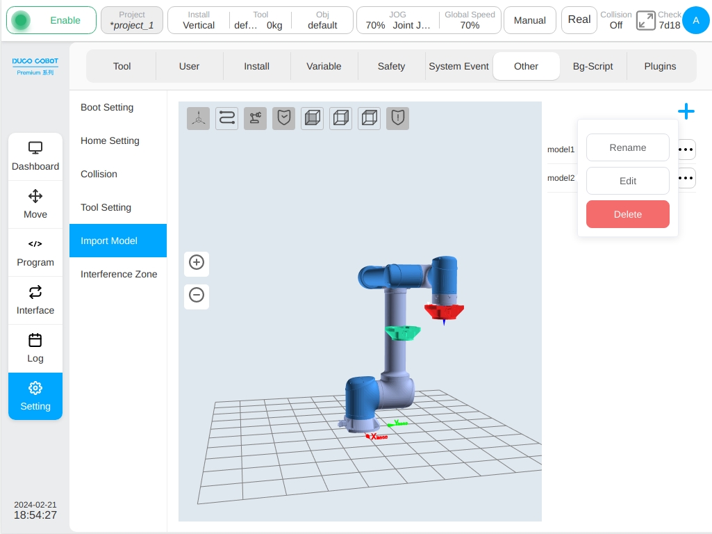
This page allows the user to import tool or artifact models and display them, the 3D simulation model is displayed on the left side of the page and the list of imported tool/artifact models is displayed on the right side. Click icon to the right of each row in the model list displays a pop-up box to rename, edit, or delete the model.
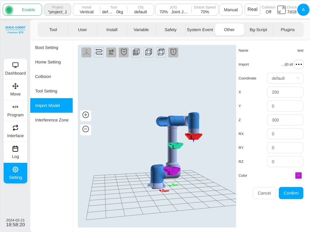
Click top right icon  popS up the virtual keyboard, enter the model name (such as: test), enter the parameter editing page of the newly added model test, as shown in the figure.

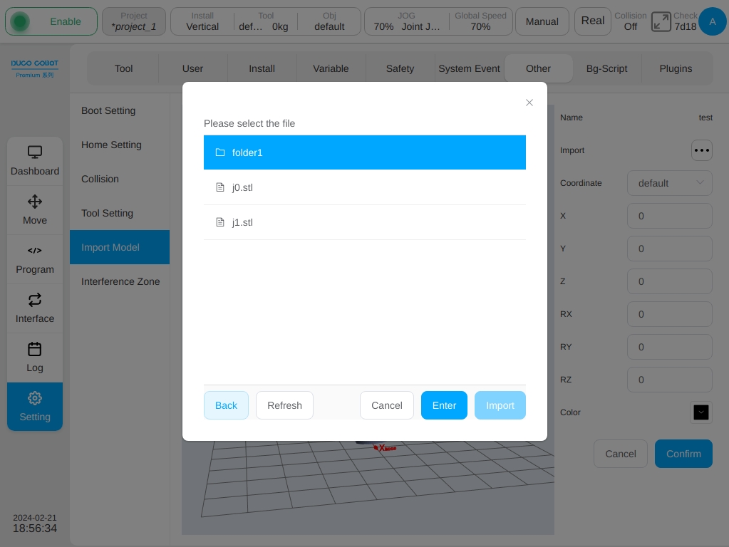
Click the ‘Import Model’ next to icon , the selection of model import mode dialog box will be displayed. There are two import modes: external import and internal import. If external import is selected, the required model file is imported from an external USB flash drive, and the size of the model file must not exceed 3M. When Internal import is selected, the required model files are imported from the system internal model folder. Model files can only have a.stl or. The format is STL.
After the model file is selected, the default reference coordinate system displayed by the model is the tool coordinate system default, the values of X, Y, Z, Rx, Ry, and Rz are all 0 by default, and the model color is black by default. Users can set the values of reference coordinate system, X, Y, Z, Rx, Ry, Rz, and model color according to their own needs.

The reference coordinate system can choose the world coordinate system, the base coordinate system, the tool coordinate system and the workpiece coordinate system. Where, the tool coordinate system and the workpiece coordinate system are the established coordinate systems in the tool setup and workpiece coordinate system pages respectively. Adjusting the model’s reference coordinate system and its offset and color parameters will transform the model’s pose and color in real time.
When editing an existing model (such as mode1), enter the model parameter editing page. If the selected tool/workpiece coordinate system parameter value is modified, it is inconsistent with the coordinate system parameter value used in the model import setting, a reminder icon  will be displayed at the reference coordinate system
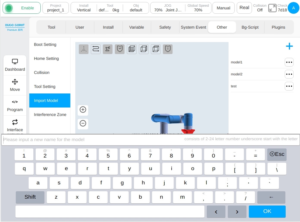
When the user renames the model, click the icon on the right of the model the ‘Rename’ button in the icon operation box will pop up a virtual keyboard, prompting you to enter a new name for the model, as shown in the figure.
When editing an existing model, click icon on the right of the model ‘Edit’ button in the icon operation box will enter the parameter editing page of the model, as shown in the above figure when creating a model. There is no unnecessary work here.
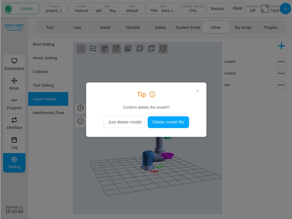
When deleting an existing model, click icon on the right of the model ‘Delete’ button in the icon operation pop-up box will display the prompt box as shown in the figure. Click the ‘Delete Model Only’ button on the right side of the pop-up box to delete only the displayed model; Clicking the ‘Delete Model File’ button will not only delete the displayed model but also delete the model file selected for the corresponding model. Click the cross in the upper right corner of the prompt box to cancel the deletion of the model.
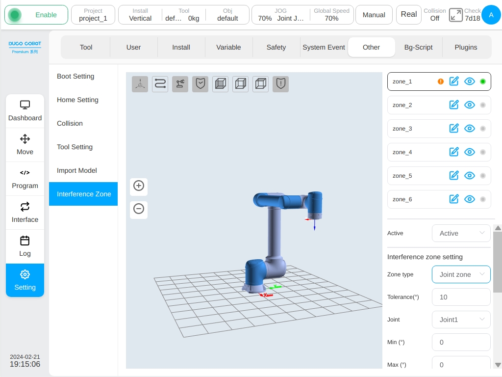
Interference Area Set
The definition types of interference region include plane, cuboid, cylinder, joint region and external axis region. The user can set up to 6 independent interference zones. After the interference area name, click icon  can switch between display and hide in the 3D display area for the interference area whose type of interference area is plane, cuboid or cylinder, and click icon after the area name (e.g. the default name zone_1) changes the name of a security zone.
  are displayed for the nterference areas that are not disabled. Otherwise,
  will be displayed. For each interference zone, after modifying any parameter, the icon will be displayed if interference zone before clicking the ‘Confirm’ button.
The activation configuration of the interference zone can be disabled or activated. Interference area action configuration activation input and response output. When the activation input signal is high power level and the TCP at the end of robot enters the interference zone, the robot will suspend the program operation. When this activation input signal disappears, the program will automatically reset and the robot will continue to run the program. Activation input Configurable general input, register BOOL input; Response output configurable general output, register BOOL output. After the robot enters the interference area, the output of the interference area is triggered. When the robot is operating in the interference area, the activation input signal of the interference area is also monitored. When the activation input signal is high power level, the operation is immediately suspended. You can configure a maximum of two intervention actions.
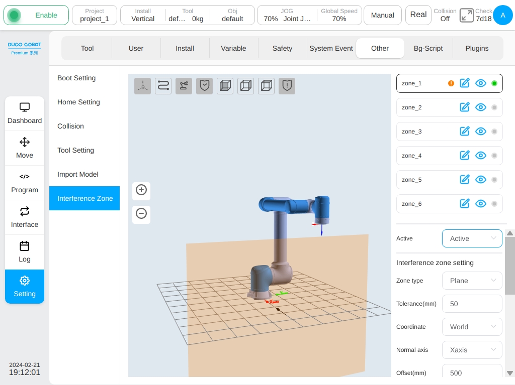
When the configuration area type is plane, the reference of the plane area is based on the world coordinate system/base/custom workpiece coordinate system, and the plane is determined by setting the plane normal axis and normal offset distance. The setting of a plane can take effect in the Select Area area, and the corresponding direction is displayed in the 3D area through the black arrow.
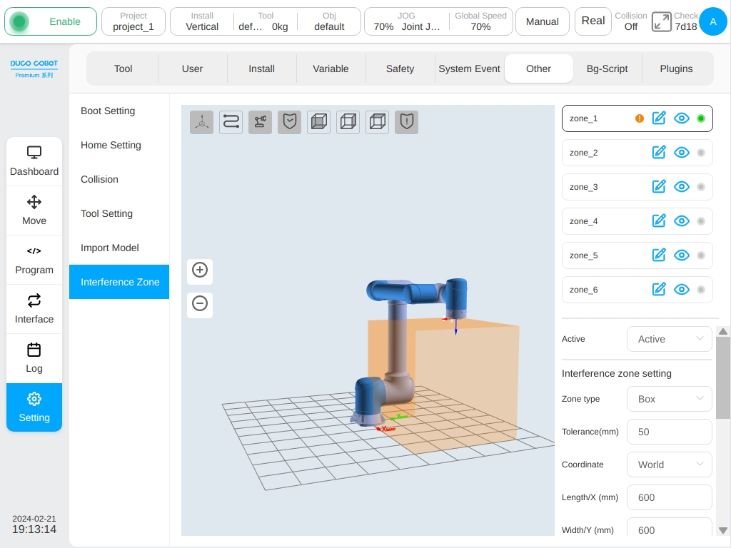
When the configuration area type is cuboid, the setting basis of the cuboid area is based on the world coordinate system/base/custom workpiece coordinate system. The workpiece coordinate system is taken as a corner point of the cuboid, and the three coordinate axis directions correspond to the length (X), width (Y) and height (Z) respectively. The length, width and height ranges from -3000mm to 3000mm.
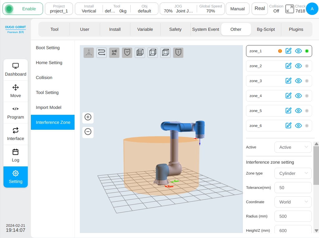
When the configuration area type is a cylinder, its setting is based on the world coordinate system/base/custom workpiece coordinate system. With the workpiece coordinate system as the center of the bottom surface of the cylinder, the Z direction points to the height direction, and the radius and height can be set. The radius ranges from 0 to 3000mm, and the height ranges from -3000mm to 3000mm.
If the configuration area type is joint area, the user can select either joint 1 or joint 6 to set the maximum value and minimum value. The maximum and minimum values range from -360° to 360°.
If the configuration area type is an external axis area, the user can set the axis name of an external axis and the maximum value (upper limit) and minimum value (lower limit) of an external axis. If no external axis is added, icon  will be displayed after the axis name. The maximum and minimum input boxes are disabled, and the ‘OK’ button at the bottom of the area configuration is disabled and cannot be clicked.
Manual-Auto Config
Some robot software features performs difference between manual mode and auto mode. To improve the performance of these features due to the real application and requirement, it is able to modify these features’ parameters by operator.
Currently, it is able to config the following manual-auto config parameters: Jog speed scale, global speed scale, collision detection scale, Pause/Stop Protect, Function IO Trigger Running and Function Register Trigger Running.
Jog speed scale:Compared to the auto mode, the maximum speed command for jog function in manual mode is automatically scaled by 25 percent in default so that the safety performance during jog process is promised. If there is a requirement to further decrease or increase the maximum speed command for jog function, the jog speed speed scale can be modified.
Global speed scale:Compared to the auto mode, the maximum speed command for all robot motion related functions, except jog function, in manual mode is automatically scaled by 25 percent in default so that the safety performance is promised in manual mode. If there is a requirement to further decrease or increase the maximum speed command, the global speed speed scale can be modified.
Note
The control command for all robot motion related functions always ensure that the safety functions, such as robot tool speed limit(TSL), robot joints speed limit(SLS) and etc, would not be triggered. So in practice, if there is no difference between the robot speed with different Jog speed scale or global speed scale, please make sure whether the robot motion already leads to a safety function violation.
Collision Detection Scale:Due to the observation error of robot joints output torque during high speed motion, the collision detection function uses a less sensitivity to detect the collision behavior in auto mode, which is about 60 percent of the sensitivity in manual mode. If higher safety performance is required, it is recommended to increase the collision detection scale to obtain higher collision detection sensitivity. Conversely, if the collision detection is always triggered in mistake during robot motion, it is recommended to further decrease the collision detection scale to obtain higher stability of features.
Pause/Stop Protect:The program system is set to be response the pause and stop opertion from UI immediately in default. In practice, mistouch may occur and it is necessary to raise a second comfimation to avoid unexpected pause and stop operation. In this circumstance, modify the configuration of Pause/Stop Protect feature is recommended.
Function IO Trigger Running:If there has a function IO input is set to be used to trig program running, the robot will response to the rising edge command signal immediately in default. In practice, this feature might cause some unexpected results during teach procedure if external signal continuously sends control signal. In this circumstance, modify the configuration of Function IO Trigger Running feature parameters is recommended, so that the safety risk can reduce.
Function Register Trigger Running:Similar to the Function IO Trigger Running feature, If there has a function Register input is set to be used to trig program running, the robot will response to the rising edge command signal immediately in default. In practice, this feature might cause some unexpected results during teach procedure if external signal continuously sends control signal. In this circumstance, modify the configuration of Function Register Trigger Running feature parameters is recommended, so that the safety risk can reduce.
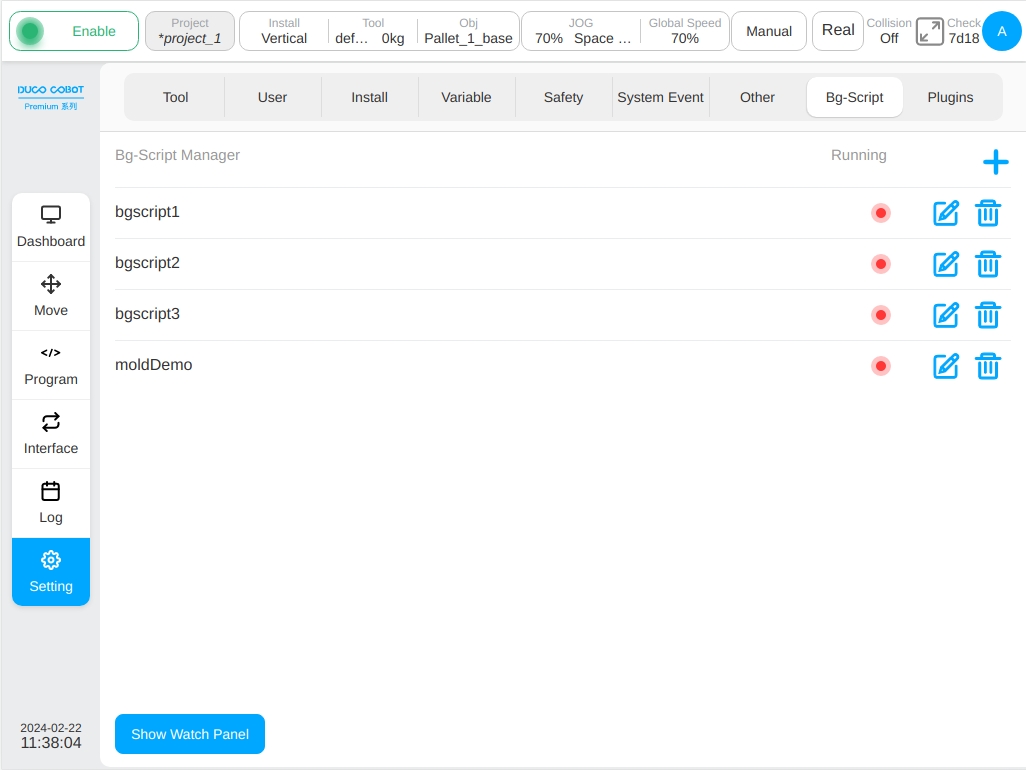
Background Script#
The ‘Background Script’ sub-page focuses on managing background programs that are independent of the robot’s program; these scripts are designed to run independently without the robot being powered up or enabled. Background scripts are used to handle periodic communications or responses to system events with complex logic. The background script management page displays a list of created background scripts, their running status, and related operation buttons that allow the user to add, edit, and delete background scripts. As shown in the figure below.
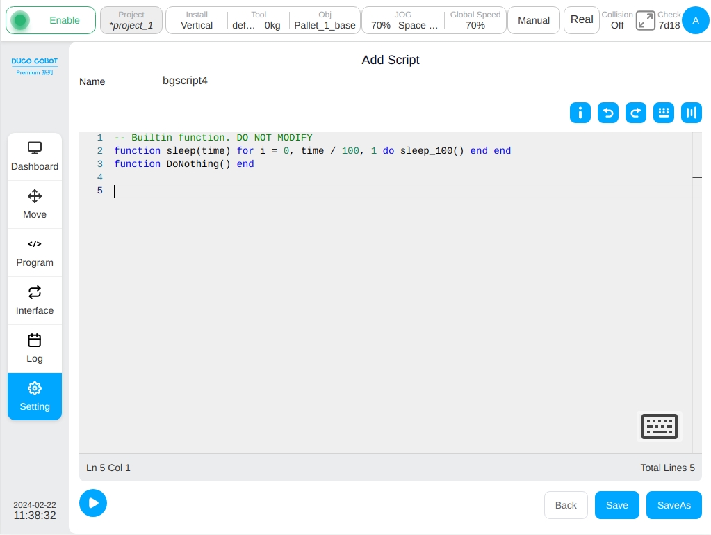
Click icon on the right top corner will arouse the virtual keyboard. The default name of background script is ‘bgscript’ with index number. After creating background script, the edit page will display as shown in the following figure.
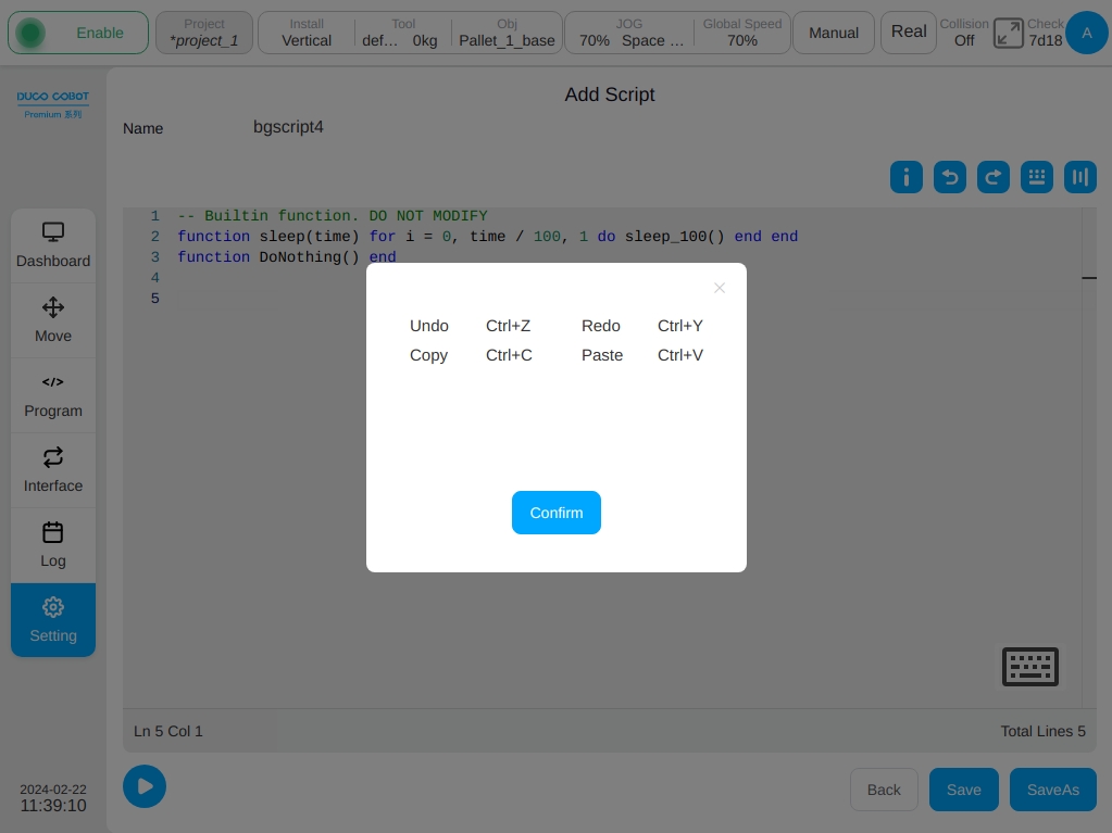
The main part of edit page is the script edition area, click icon  will pop up the prompt diaglog of shortcut key, as shown in the following figure. Icon
  is the ‘Undo’ button, icon
  is the recover button. Click icon
  will pop up the floating shortcut keyboard window, which can be dragged and located.
As shown in the following figure, click icon  will display the system variables. Click icon
  to hide the system variable.
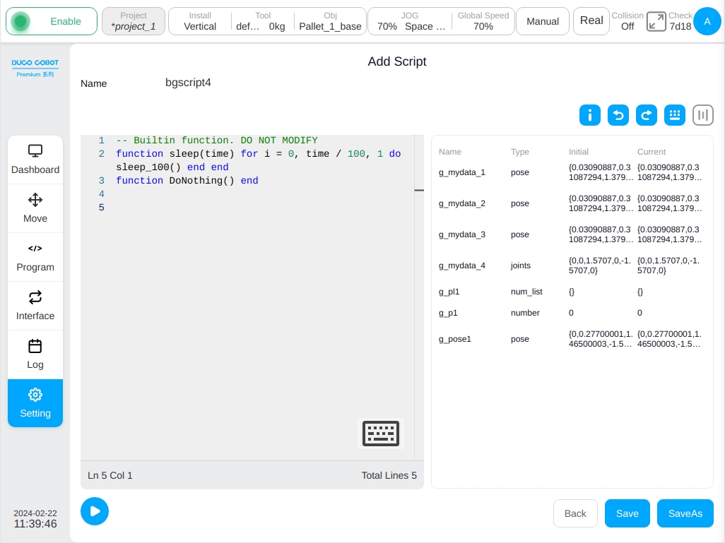
After editing the disigned background script, click the ‘Save’ icon at the right below corner to save the current background script. Returning to the background script management page, all the created background scripts will display. It is also feasible to save the background script as a copy by clicking the ‘Save As’ button. Click the ‘Run’ button with icon  , all created background scripts will start to run and the running state of background scripts will display with .
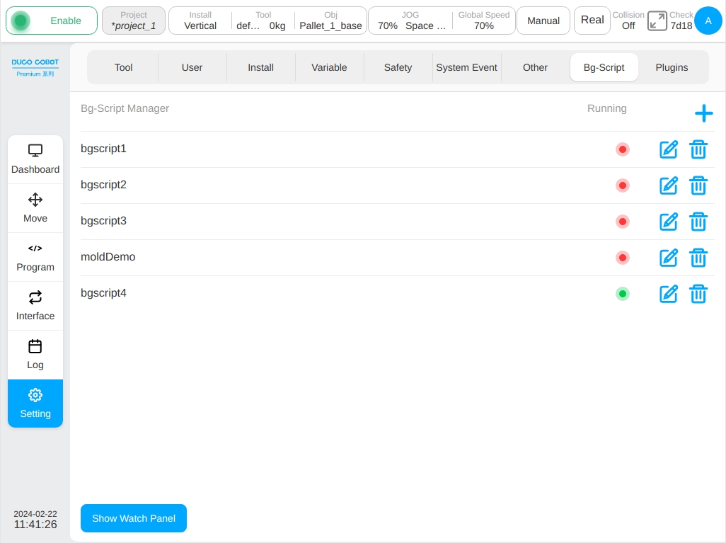
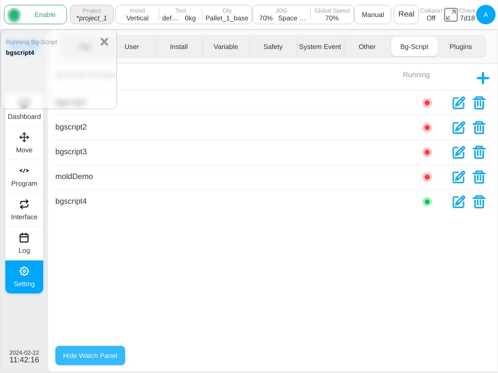
The floating window, which displays all the background scripts in running state, can be aroused by clicking the ‘Display Running’ window at the buttom left corner. Such as:
To edit the existing background scripts, click the icon and then enter the edit interface again. Click icon on the right of background script name will delete the corresponding background script.
Caution
At the end of each background script and the ‘while’ loop exists in all background script, it is necessary to add ‘Sleep’ script to ensure the background script would not cause a control suystem overload, which would lead to robot control system throw unexpected error.
Caution
All scripts related to robot move control are not allowed to be added in the background script