External Interfaces of the Control Cabinet#
The external user interfaces of the control cabinet are mainly distributed at the bottom of the control cabinet, and the interface diagram and description are shown in Figure 4:
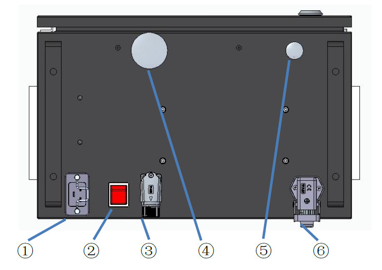
Figure 4 Interfaces at the Bottom of the Control Cabinet
1 —— AC input interface
2 —— System switch
3 —— Teaching pendant interface
4 —— Reserved hole 2
5 —— Reserved hole 1
6 —— Robot arm interface
AC Input#
The power supply input for the DC15S control cabinet is: 100-240VAC, 47-63HZ, 10A;
The power supply inputs for the DC30D control cabinet are: 200-240VAC, 47-63HZ, 10A; 100-240VAC, 47-63HZ, 16A;
(The AC input is a C20 socket with a filter function, and the power cord needs to use a standard C19 IEC 60320 plug)
System Switch#
The system switch is used to turn the power of the control cabinet on or off, enabling the power-on function of the entire system. When in the “┃” position, the system is connected to the mains supply. In this state, press the power-on button to start the operation, and the system will power on and work normally. When in the “◎” position, the system is disconnected from the power supply, and the system is in a power-off state with no power input, so the system cannot be started (Note: If the AC input is not disconnected, the incoming line terminal is live at this time, so do not touch it).
The power-on sequence of the robot system is: Connect the AC input of the control cabinet and supply power → Press the system switch to the “┃” position → Press the power-on button → The system powers on → The robot powers on; The power-off sequence of the system is: Power off through the robot UI interface on the teaching pendant (the robot powers off) → Shut down the system through the teaching pendant interface → Press the system switch to the “◎” position → Disconnect the AC input of the control cabinet.
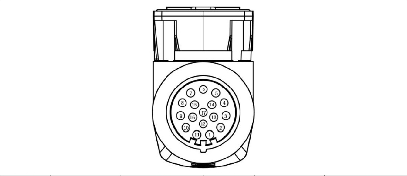
Teaching Pendant Interface#
Table 3 shows the robot teaching pendant interface. For the model of the teaching pendant, please refer to the specification list for selection. The definition of its internal wiring harness interface is as follows:
Table 3 Teaching Pendant Interface
|
Signal Definition |
Remarks |
Connector Number |
Signal Definition |
Remarks |
|---|---|---|---|---|---|
1 |
24V |
Power Supply 24V |
2 |
0V |
Power Supply 0V |
3 |
EMG1+ |
Emergency Stop Signal 1+ |
4 |
EMG1- |
Emergency Stop Signal 1- |
5 |
EMG2+ |
Emergency Stop Signal 2+ |
6 |
EMG2- |
Emergency Stop Signal 2- |
7 |
EN1+ |
Three-position Enable 1+ |
8 |
EN1- |
Three-position Enable 1- |
9 |
PUSH+ |
Power On/Off Signal + |
10 |
PUSH- |
Power On/Off Signal - |
11 |
/ |
Empty |
12 |
EN2+ |
Three-position Enable 2+ |
13 |
Eth_T_P |
Ethernet T+ |
14 |
Eth_T_N |
Ethernet T- |
15 |
Eth_R_P |
Ethernet R+ |
16 |
Eth_R_N |
Ethernet R- |
17 |
EN2- |
Three-position Enable 2- |
Reserved Holes 1 and 2#
Reserved Hole 1 is a circular hole with a diameter of Ф18. Reserved Hole 2 is a circular hole with a diameter of Ф40.
When functions such as digital IO, safety IO, and remote switches need to be used, external wire harnesses can be connected into the control cabinet through the reserved holes.
Method for removing the blanking cover: As shown in the figure, squeeze the buckle of the blanking cover toward the center of the circle, then push it outward, and the blanking cover can be removed.

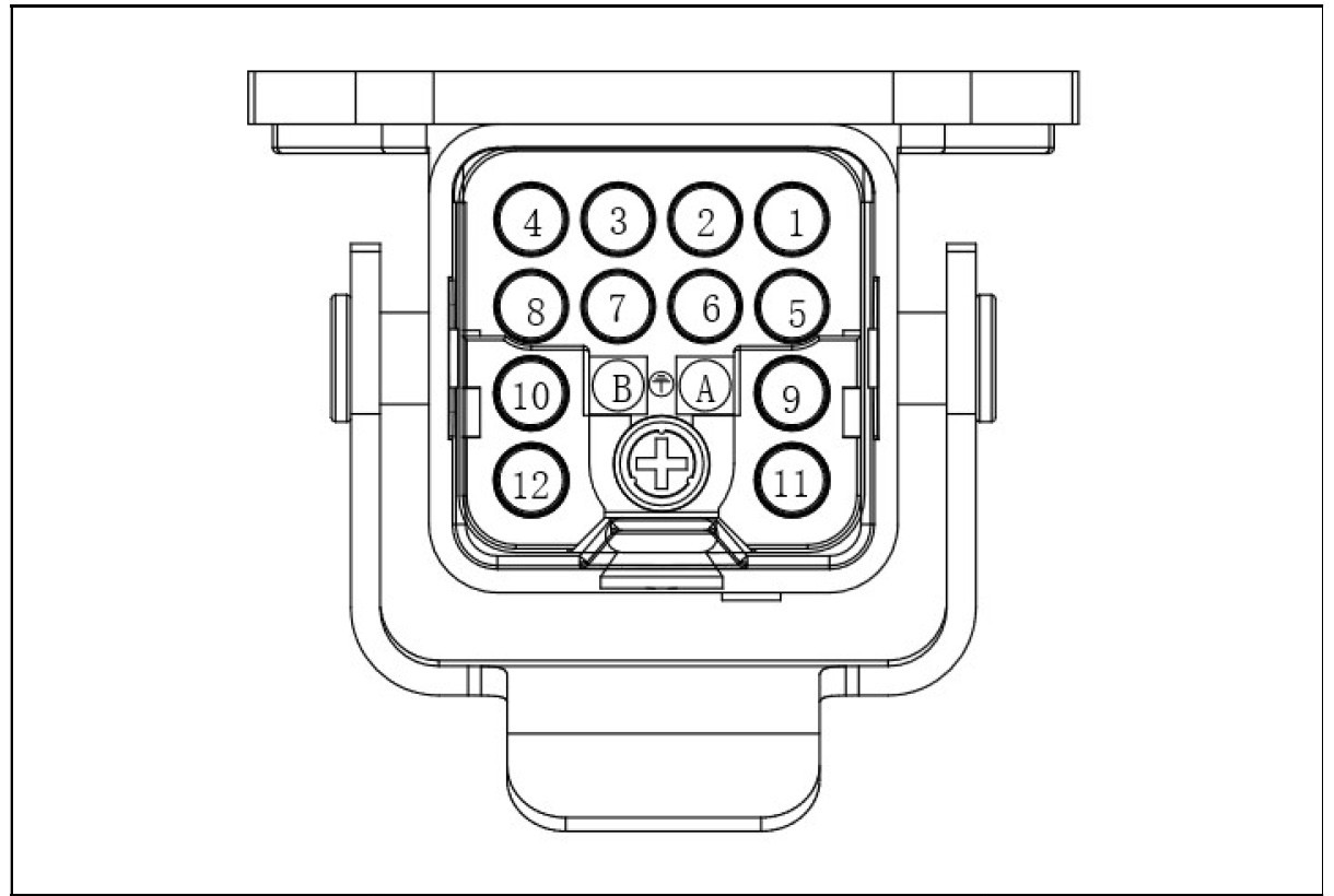
Robot Arm Interface#
The definitions of the robot interfaces for the DC15S & DC30D control cabinets are shown in Table 2:
Table 2 Definitions of Robot Interfaces for DC15S & DC30D Control Cabinets
Connector Number |
Signal Definition |
Remarks |
9 |
48V |
|
10 |
48V |
|
11 |
GND |
|
12 |
GND |
|
PE |
PE |
|
5 |
PE |
|
8 |
PE |
|
1 |
EtherCAT Tx+ |
|
2 |
EtherCAT Tx- |
|
3 |
EtherCAT Rx+ |
|
4 |
EtherCAT Rx- |