Internal Interfaces of the Control Cabinet#
The internal user interfaces of the R2 control cabinet and their descriptions are shown in the following figure: Among them, (1) is the external interface of the teaching pendant emergency stop shielding adapter board, (2) — (5) are the external interfaces of the industrial computer, and (6) — (12) are the external interfaces of the safety control board.

Figure 5 Internal User Interface Diagram of R2 Control Cabinet
No. |
Interface Name |
No. |
Interface Name |
|---|---|---|---|
1 |
TP Jumper |
2 |
VGA&COM3/4 |
3 |
LAN1+USB3.0 |
4 |
LAN2 (Occupied by Teach Pendant) +USB2.0 |
5 |
COM1 |
6 |
IO POWER |
7 |
SIO (Safety IO) |
8 |
DIO (Digital IO) |
9 |
CIO (Configurable IO) |
10 |
EIO (Function Expansion IO) |
11 |
EtherCAT2 |
12 |
ON/OFF (Power Switch) |
TP Jumper Interface#
This interface is the teach pendant emergency stop shielding interface of the R2 control cabinet. It is used for robot mode switching, emergency stop function or emergency stop short-circuit function after the teach pendant is unplugged.
The definition of the teach pendant shielding interface of the control cabinet is shown in Table 3: It is recommended that the wire harness here use 22AWG (0.2-0.3mm²) or smaller, and an 8mm-length tubular terminal.
Table 3 Teach Pendant Shielding Interface

Connector Number |
Signal Definition |
Remarks |
1 |
EMG1+ |
(Teach Pendant Emergency Stop Input 1+) |
2 |
EMG1- |
(Teach Pendant Emergency Stop Input 1-) |
3 |
EMG2+ |
(Teach Pendant Emergency Stop Input 2+) |
4 |
EMG2- |
(Teach Pendant Emergency Stop Input 2-) |
5 |
SEL1+ |
(Mode Switch Input 1+) |
6 |
SEL1- |
(Mode Switch Input 1-) |
7 |
SEL2+ |
(Mode Switch Input 2+) |
8 |
SEL2- |
(Mode Switch Input 2-) |
Application Example (for scenarios where one teach pendant is used with multiple control cabinets):
After debugging is completed, rotate the mode selection (key) switch on the teach pendant to set the robot to the automatic operation mode. Please prepare the wire harness required as shown in the figure in advance.
Use the emergency stop button wire harness shown in the left figure (optional accessory, default wire length 5m) to short-circuit the emergency stop and mode switch.

Note: After using the above wire harness to short-circuit the emergency stop shield, the emergency stop function of the teach pendant will become invalid immediately. Please ensure that the robot is equipped with the emergency stop button wire harness system shown in the left figure as required or other external emergency stops configured in accordance with relevant safety regulations.
Insert the above wire harness or shorting wire into the teach pendant shielding interface in the correct wire sequence, and then unplug the teach pendant. At this time, the operating state of the robot will not be affected.
When it is necessary to plug the teach pendant back in for manual operation, first set the mode selection switch of the teach pendant to the automatic operation mode, then insert the teach pendant into the teach pendant interface of the control cabinet, then pull out the emergency stop button wire harness or shorting plug, and then you can operate the robot normally through the teach pendant.
Note: Except for the situation where the shorting plug and the teach pendant are connected to the control cabinet at the same time during the process of plugging and unplugging the teach pendant, the shorting plug and the teach pendant are not allowed to be connected to the control cabinet at the same time at any other time.
For scenarios where one teach pendant is used with one control cabinet, this interface is prohibited from being used.
VGA & COM3, 4 Interfaces#
The VGA & COM3/4 interfaces are used for signals related to the display of the teach pendant screen and the operation of the teach pendant with the teach pendant junction box. Their interface definitions are shown in Table 10:
Table 10 Definitions of Teach Pendant VGA + 232 Interfaces

Number |
Signal Definition |
Number |
Signal Definition |
|---|---|---|---|
1 |
COM3_TX |
14 |
COM4_RX |
2 |
COM4_TX |
15 |
GND_ISO |
3 |
COM3_RX |
16 |
GND_ISO |
4 |
GND_ISO |
17 |
GND |
5 |
GND_ISO |
18 |
GND |
6 |
GND |
19 |
VGA_SCL |
7 |
GND |
20 |
VGA_SDA |
8 |
|
21 |
GND |
9 |
22 |
GND |
|
10 |
GND |
23 |
GND |
11 |
GND |
24 |
VGA_G |
12 |
VGA_B |
25 |
GND |
13 |
5V |
26 |
VGA_R |

LAN1 + USB3.0 Interface#
The LAN1 interface, with a speed of 1000M, supports PROFINET / MODBUS TCP / TCP IP communication, and is used for communicating with other controllers and robots to realize robot control; it is a standard network cable interface, and the interface definition is not listed here.
The USB3.0 interface is used to connect devices such as a mouse and keyboard, and also facilitates technicians to connect U disk devices for software copying. It is a standard USB3.0 interface, and the interface definition is not listed here.
LAN2 + USB2.0 Interface#
The LAN2 interface, with a speed of 100M, supports MODBUS TCP / TCP IP communication and is used for communicating with other controllers and robots to realize robot control; it is a standard network cable interface, and the interface definition is not listed here. (When the R2 control cabinet is equipped with a wired teach pendant, this interface will be occupied by the teach pendant communication.)
The USB2.0 interface is used to connect devices such as a mouse and keyboard, and also facilitates technicians to connect U disk devices for software copying. It is a standard USB2.0 interface, and the interface definition is not listed here. (This interface is recommended when a Wi-Fi communication module is optional.)

COM1 Interface#
The COM1 interface is an RS232 interface;
This interface is a DB9 female connector with male pins; its interface definition is shown in Table 11:
Table 11 Definition of COM1 Interface

Number |
Signal Definition |
Number |
Signal Definition |
|---|---|---|---|
1 |
NC |
2 |
COM1_RX |
3 |
COM1_TX |
4 |
NC |
5 |
GND_ISO |
6 |
NC |
7 |
NC |
8 |
NC |
9 |
NC |
IO POWER Interface#
The IO POWER (IO Power Supply) interface is used for power supply of SIO (Safety IO), DIO (Digital IO), CIO (Configurable IO) interfaces and internal circuits. Its interface definition is shown in Table 12:
It is recommended that the wire harness here use 22AWG (0.2-0.3mm²) or smaller, and an 8mm-length tubular terminal.
Table 12 Definition of IO POWER Interface

Number |
Signal Definition |
Number |
Signal Definition |
|
1 |
Power (Controller 24V Output +) |
3 |
GND (Controller 24V Output -) |
|
2 |
DC24V (10 Power Supply Input +) | 4 |
0V (10 Power Supply Input -) |
||
Note: According to the power of the IO load, two power supply modes can be selected: internal power supply and external power supply.
For internal power supply, short-circuit pin 1 with pin 2, and pin 3 with pin 4; at this time, the internal will provide 24V DC with a maximum of 2A (as shown in the figure).

For external power supply, remove the shorting wire, connect pin 2 to an external DC24V power supply, and connect pin 4 to the 0V of the external power supply; in addition, short-circuit pin 3 with pin 4 for common grounding. After power supply is applied, the 0V of the external power supply will be connected to the 48V power supply ground of the system. Note that if the external power supply used has its 0V short-circuited with the external power supply’s housing, the housing must not be connected to the system’s housing (PE) during installation. When using external power supply, it can carry a maximum of 8A of 24V DC power (as shown in the figure).


SIO Interface#
The SIO (Safety IO) interface is an external emergency stop and safety input/output interface provided by the controller, including 1 channel of user emergency stop signal input, 1 channel of system emergency stop feedback output, 1 channel of protective stop input, 2 channels of configurable safety inputs, and 2 channels of configurable safety outputs (all safety inputs and outputs are active signals).
Among them, the emergency stop signal input, protective stop input, and configurable safety inputs are dry contact interfaces;
When using the configurable safety outputs and system emergency stop feedback output, it is recommended to use solid-state relays for transfer. It is strongly recommended to use diode protection for inductive small relays.
Note: The system emergency stop feedback output is defaulted to a high-level active output. When wiring, please note to work after shutdown! Do not work with electricity!
For the operation instructions of setting other interfaces through software, please refer to the Duco core User Manual. The interface definition is shown in Table 13:
Table 13 Definition of SIO Interface

Number | Signal Definition |
Number | Signal Definition |
||
|---|---|---|---|
1 |
EI1+ (User Emergency Stop Signal Input 1+) |
2 |
EI1- (User Emergency Stop Signal Input 1-) |
3 |
EI2+ (User Emergency Stop Signal Input 2+) |
4 |
EI2- (User Emergency Stop Signal Input 2-) |
5 |
PS1+ (Protective Stop Input 1+) |
6 |
PS1- (Protective Stop Input 1-) |
7 |
PS2+ (Protective Stop Input 2+) |
8 |
PS2- (Protective Stop Input 2-) |
9 |
CI1_1+ [Configurable Safety Input 1 (1+)] |
10 |
CI1_1- [Configurable Safety Input 1 (1-)] |
11 |
CI1_2+ [Configurable Safety Input 1 (2+)] |
12 |
CI1_2- [Configurable Safety Input 1 (2-)] |
13 |
CI2_1+ [Configurable Safety Input 2 (1+)] |
14 |
CI2_1- [Configurable Safety Input 2 (1-)] |
15 |
CI2_2+ [Configurable Safety Input 2 (2+)] |
16 |
CI2_2- [Configurable Safety Input 2 (2-)] |
17 |
|
||
19 |
EO2+ (System Emergency Stop Feedback Output 2+) | 20 | EO2- (System Emergency Stop Feedback Output 2-) (24V output by default) |
||
21 |
CSO1_1+ [Configurable Safety Output 1 (1+)] |
22 |
CSO1_1- [Configurable Safety Output 1 (1-)] |
23 |
CSO1_2+ [Configurable Safety Output 1 (2+)] |
24 |
CSO1_2- [Configurable Safety Output 1 (2-)] |
25 |
CSO2_1+ [Configurable Safety Output 2 (1+)] |
26 |
CSO2_1- [Configurable Safety Output 2 (1-)] |
27 |
CSO2_2+ [Configurable Safety Output 2 (2+)] |
28 |
CSO2_2- [Configurable Safety Output 2 (2-)] |

SIO Interface Power Status Table:
SIO Interface |
220VAC Power-on |
Power-on State*1 |
Power-on & Power-off (Robot Arm) |
Open Configuration CSO |
EI*&CI* |
No Power |
24V |
24V |
24V |
EO* |
No Power |
24V |
24V |
24V |
CSO* |
No Power |
No Power |
No Power |
24V |
*1 The power-on state can be entered by pressing the power-on button on the teach pendant, the power-on button on the box, or via remote power on.
It is recommended that the wire harness here use 22AWG (0.2-0.3mm²) or smaller, and a 8mm-length tubular terminal.
The electrical parameters of the safety IO interface are shown in Table 14:
Table 14 Parameter Table of Safety IO Interface (PNP Type)
Safety DI |
|||||
Terminal |
Parameter |
||||
EIx |
Dry contact input |
||||
PSIx |
Dry contact input |
||||
CSIx |
Dry contact input |
||||
Safety DO |
|||||
Terminal |
Parameter |
Minimum |
Typical |
Maximum |
|
EOx/CSOx |
Current |
0A |
— |
0.2A |
|
Voltage |
23.52V |
24V |
25.2V |
||
Signal Type | PNP |
|||||
The timing diagram of Safety DI is shown in Figure 8:

Figure 8 Timing Diagram of Safety Input
The diagnostic pulse at the Safety DI input terminal is shown in Figure 7. The MCU checks whether the hardware circuit is faulty by sending diagnostic pulses. The diagnostic pulse has a period of 20ms and a negative pulse width of 500 (±100) μs.
The timing of Safety DO is shown in Figure 9:

Figure 9 Timing Diagram of Safety Output
The diagnostic pulse at the output terminal of Safety DO is shown in Figure 8. The output control signal sent by the MCU carries a diagnostic pulse signal, which has a period of 160ms and a negative pulse width of 600 (±100) μs.
SIO Interface Wiring Diagram#
Default Safety Configuration
Figure 10 shows the wiring diagram of the default configuration for the safety interface, which allows robot operation without any additional safety devices.

Figure 10 Default Safety Configuration Wiring Diagram
Connecting External Safety Input Signals
Figure 11 shows the wiring diagram for connecting external safety input signals to the safety input interface. Note that the external safety input signals are dry contact signals, and the emergency stop button is taken as an example of the external safety input signal.

Figure 11 External Safety Signal Input Wiring Diagram
Connecting Protective Stop Signals
Figure 12 shows the wiring diagram for protective stop input signals. Note that the external protective stop input signals are dry contact signals.

Figure 12 Protective Stop Signal Input Wiring Diagram
Connecting Configurable Safety Input Signals
The wiring diagram for configurable safety input signals is similar to that for protective stop input signals.
Sharing Emergency Stop with Other Machines
When robots are used in conjunction with other machines, it is often necessary to set up a common emergency stop circuit. By setting up a common line, operators do not have to think about which emergency stop button to use.
Since both machines need to wait for each other to exit the emergency stop condition, the standard robot emergency stop input cannot be used for sharing. To share the emergency stop function with other machines, it must be configured through the safety input and safety output of the controller’s safety IO.
In addition, the safety output is an active signal and needs to be used after being transferred through a solid-state relay, as shown in Figure 13:

Figure 13 Schematic Diagram of Emergency Stop Cascading for Two Robot Controllers
DIO Interface#
The DIO (Digital IO) interface provided by the controller includes 8 channels of digital input (DI) interfaces and 8 channels of digital output (DO) interfaces. Its interface definition is shown in Table 15:
It is recommended that the wire harness here use 22AWG (0.2-0.3mm²) or smaller, and a 8mm-length tubular terminal;
Table 15 Definition of DIO Interface

Number | Signal Definition |
Number | Signal Definition |
||
|---|---|---|---|
1 |
24V |
2 |
0V |
3 |
24V |
4 |
0V |
5 |
DI1 (General DI Input 1) |
6 |
DO1 (General DO Output 1) |
7 |
DI2 (General DI Input 2) |
8 |
DO2 (General DO Output 2) |
9 |
DI3 (General DI Input 3) |
10 |
DO3 (General DO Output 3) |
11 |
DI4 (General DI Input 4) |
12 |
DO4 (General DO Output 4) |
13 |
DI5 (General DI Input 5) |
14 |
DO5 (General DO Output 5) |
15 |
DI6 (General DI Input 6) |
16 |
DO6 (General DO Output 6) |
17 |
DI7 (General DI Input 7) |
18 |
DO7 (General DO Output 7) |
19 |
DI8 (General DI Input 8) |
20 |
DO8 (General DO Output 8) |
21 |
24V |
22 |
0V |
23 |
24V |
24 |
0V |
Digital Input (DI)#
The digital input (DI) interface provided by the controller has an input voltage range of: -3-30VDC (0~15mA). The electrical parameters of the interface are shown in Table 16:
Table 16 DI Interface Parameter Table (PNP Type)
Terminal |
Parameter |
Minimum |
Typical |
Maximum |
Digital Input |
||||
DIX-24V |
Voltage |
-3V |
—— |
30V |
DIX-24V |
ON Region |
11V |
—— |
30V |
DIX-24V |
OFF Region |
-3V |
—— |
5V |
DIX-24V |
TON/TOFF Delay |
TON:50ms TOFF: 50ms |
||
DIX-24V |
Function |
PNP Type |
||
Dry contact signal input
Figure 14 shows the wiring method between the dry contact signal (button) and the DI port.

Figure 14 Wiring Diagram of Dry Contact Signal Input
PNP signal input
Figure 15 shows the wiring method between the PNP signal (output from the DO port of PLC, PNP type) input and the DI port.

Figure 15 Wiring Diagram of PNP Signal Input
Digital Output (DO)#
The digital output (DO) interface provided by the controller has an output voltage range of 23.52-25.2VDC, a maximum current of 0.5A, and switching time. The electrical parameters of the interface are shown in Table 17:
Table 17 DO Interface Parameter Table (PNP Type)
Terminal |
Parameter |
Minimum |
Typical |
Maximum |
Digital Output |
||||
DOX-0V |
Current |
0A |
—— |
0.5A |
DOX-0V |
Voltage |
23.52V |
—— |
25.2V |
DOX-0V |
TON/TOFF Delay |
TON:50ms TOFF: 50ms |
||
DOX-0V |
Function |
PNP Type |
||
DO output connected to load
Figure 16 shows the wiring diagram for the direct connection of DO output to a load (relay), with a maximum output current of 0.5A.

Figure 16 Reference Wiring Diagram of DO Output and Load
Wiring diagram of DO output and other PNP input devices
Figure 17 shows the wiring diagram between the DO port output and other PNP-type DI input devices (PLC):

Figure 17 Wiring Diagram with Other PNP-type DI Input Devices
CIO Interface#
The CIO (Configurable Digital IO) interface provided by the controller includes 8 channels of configurable digital input (DI) interfaces and 8 channels of configurable digital output (DO) interfaces; this interface can be configured as user DIO or functional DIO through software operation, and it is set as user DIO by default; its interface definition is shown in Table 18:
It is recommended that the wire harness here use 22AWG (0.2-0.3mm²) or smaller, and a 8mm-length tubular terminal;
Table 18 Definition of Configurable Digital IO Interface

Number |
Signal Definition |
Number |
Signal Definition |
|---|---|---|---|
1 |
24V |
2 |
0V |
3 |
24V |
4 |
0V |
5 |
CDI1 (Configurable DI Input 1) |
6 |
CDO1 (Configurable DO Output 1) |
7 |
CDI2 (Configurable DI Input 2) |
8 |
CDO2 (Configurable DO Output 2) |
9 |
CDI3 (Configurable DI Input 3) |
10 |
CDO3 (Configurable DO Output 3) |
11 |
CDI4 (Configurable DI Input 4) |
12 |
CDO4 (Configurable DO Output 4) |
13 |
CDI5 (Configurable DI Input 5) |
14 |
CDO5 (Configurable DO Output 5) |
15 |
CDI6 (Configurable DI Input 6) |
16 |
CDO6 (Configurable DO Output 6) |
17 |
CDI7 (Configurable DI Input 7) |
18 |
CDO7 (Configurable DO Output 7) |
19 |
CDI8 (Configurable DI Input 8) |
20 |
CDO8 (Configurable DO Output 8) |
21 |
24V |
22 |
0V |
23 |
24V |
24 |
0V |
Note: For instructions on configuring this interface as user DIO or functional DIO through software settings, please refer to the Duco core User Manual.
Configurable Digital Input (CDI)#
The controller provides a Configurable Digital Input (CDI) interface, with an input voltage range of: -3-30VDC (0~15mA).
Please refer to the chapter description of 4.10.1 Digital Input (DI) for the interface parameter table, timing diagram, and wiring method.
Configurable Digital Output (CDO)#
The controller is equipped with a Configurable Digital Output (CDO) interface, which has an output voltage range of 23.52-25.2VDC and a maximum current of 0.5A.
For the interface parameter table, timing diagram, and wiring method, please refer to the description in section 4.10.2 Digital Output (DO).
EIO Interface#
The EIO (Function Expansion IO) interface of the DC00 controller is an interface provided by the controller for external use, including 2 channels of voltage analog input interfaces, 2 channels of voltage analog output interfaces, 1 channel of external CAN communication interface, 1 channel of external RS485 communication interface, an INC encoder differential signal interface, and 1 channel of remote up/down point interface. Its interface definition is shown in Table 19:
It is recommended that the wire harness here use 22AWG (0.2-0.3mm²) or smaller, and an 8mm-length tubular terminal;
Note: If the 24V power supply of the INC encoder is short-circuited, it may cause damage to the slave interface board. Avoid short circuits during use.
Table 19 Definition of Function Expansion 1 Interface

Number |
Signal Definition |
Number |
Signal Definition |
|---|---|---|---|
1 |
AI1 (Voltage Analog Input 1) |
2 |
AG (Analog Ground) |
3 |
AI2 (Voltage Analog Input 2) |
4 |
AG (Analog Ground) |
5 |
AO1 (Voltage Analog Output 1) |
6 |
AG (Analog Ground) |
7 |
AO2 (Voltage Analog Output 2) |
8 |
AG (Analog Ground) |
9 |
24VE |
10 |
RC1 (Remote Switch ON+) |
11 |
GND |
12 |
PowerON (Remote Switch ON-) |
13 |
A+ (INC Signal Phase A+) |
14 |
RC2 (Remote Switch OFF+) |
15 |
A- (INC Signal Phase A-) |
16 |
PowerOFF (Remote Switch OFF-) |
17 |
A- (INC Signal Phase A-) |
18 |
CAN_L |
19 |
B- (INC Signal Phase B-) |
20 |
CAN_H |
21 |
Z+ (INC Signal Phase C+) |
22 |
485_B |
23 |
Z- (INC Signal Phase C-) |
24 |
485_A |
Voltage Analog Interface#
Voltage Analog Input (0~10V ±1%)
The voltage analog input is factory-set to a default input voltage range of 0-10V (with an accuracy of ±1%).
Voltage Analog Output (0~10V, ±1%)
The voltage analog output is factory-set to a default output voltage of 0V.
Analog Signal Isolation Specifications
Analog signals are electrically isolated from each other, and the electrical specifications refer to Table 20 as follows:
Table 20 Analog Electrical Specifications
Terminal |
Parameter |
Minimum |
Typical |
Maximum |
Voltage Analog Input |
||||
AI_VX-AGND |
Voltage |
0V±1% |
—— |
10V±1% |
Resistance |
— |
48kΩ |
— |
|
Resolution |
— |
12-bit |
— |
|
l Schematic Diagram of Analog Wiring
Figure 18 shows the schematic diagram of the analog interface wiring:

Figure 18 Schematic Diagram of Analog Input Wiring
Communication Interfaces (CAN, RS485, INC Signals)#
The external communication interfaces are signal-isolated from each other, and the communication parameter specifications refer to Table 21 as follows:
Table 21 Communication Parameter Specifications
Terminal |
Parameter |
Data |
CAN Communication |
Baud Rate |
10k, 20k, 50k, 100k, 125k, 250k, 500k, 1000k bps |
RS485 Communication |
Baud Rate |
|
|
Supply Voltage |
24VDC |
Allowed Frequency |
<200KHz |
|
Input Signal |
Square Wave Signal (Compatible with Single-ended/Differential) |
INC Interface Description#
Before wiring the INC, it is necessary to first check the form of the output circuit of the INC encoder. The following are examples of wiring methods for several common output forms:

Remote Switch Interface#
A remote switch allows the system to be turned on or off without using the power-on button on the teaching pendant or controller panel.
The “PowerON” input works on the same principle as the power-on button. It is essential to use the “PowerOFF” input for remote shutdown, as this signal enables the controller to save open files and shut down normally (similar to a system soft shutdown).
The definition of the remote switch interface is shown in Table 22:
Table 22 Definition of Remote Switch Interface
Connector Number |
Signal Definition |
Input Signal Type |
10 |
RC1 |
Dry Contact |
12 |
PowerON |
|
14 |
RC2 |
Dry Contact |
16 |
PowerOFF |
The electrical specifications are as shown in Table 23 below:
Table 23 Electrical Specifications of Remote Switch Interface
Terminal |
Parameter |
Minimum |
Maximum |
PowerON-RC1 |
Voltage |
0VDC |
25.2VDC |
PowerOFF -RC2 |
Voltage |
0VDC |
25.2VDC |
PowerON Activation Time |
>1S |
||
PowerOFF Shutdown Time |
>3S |
||
The wiring method of the remote switch is as follows:
Remote PowerON Interface (Dry Contact Input)
Figure 21 shows the wiring method of the remote PowerON button, where a self-resetting button is used.

Figure 21 Schematic Diagram of Remote Power-On Wiring
Remote PowerOFF Interface (Dry Contact Input)
Figure 22 shows the wiring method of the remote PowerOFF button, where a self-resetting button is used.

Figure 22 Schematic Diagram of Remote Power-Off Wiring
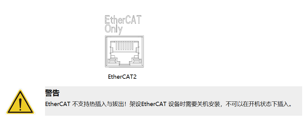
EtherCAT2 Interface#
The EtherCAT2 interface supports EtherCAT communication; it is reserved for backup use. It is a standard network cable interface, and the interface definition is not listed here.