DC00-J9 Controller#
The DC00 controller, whose appearance is shown in Figure 6, can be independently selected as a control unit. It provides functions such as algorithm implementation, motion control, and human-machine interaction for the robot system, and the peripheral interfaces offer functions like external communication and IO interfaces.

Figure 6 Appearance Diagram of DC00 Controller
Basic Parameters#
Specification Parameters of DC00 Controller
Parameter |
Specification |
Weight |
2.5kg |
Dimensions |
252x173x67mm |
Ambient Temperature and Humidity |
-10-45℃, 20%-70%RH |
Protection Class |
IP30 |
Material |
Steel, aluminum alloy shell |
Input Power |
DC48V (45-59.2V), DC24V (22-26V) |
Power |
100W |
Communication Interfaces |
Supports CAN, RS485, LAN, EtherCAT |
Communication Methods |
TCP/IP, Modbus TCP, Modbus RTU |
I/O Ports |
8 channels of DI, 8 channels of DO, 8 channels of configurable IO |
Function Expansion IO |
interface |
Usage Requirements#
When users use the robot and DC00 control cabinet, they must operate in accordance with the recommended electrical parameters. Reaching or exceeding the limit parameters may cause damage to the controller hardware.
Power Supply Requirements#
The DC00 control cabinet requires two sets of external power supplies: DC24V and DC48V. These two sets of power supplies are isolated from each other and do not share a common ground.
Voltage Range |
Minimum Value |
Maximum Value |
|---|---|---|
DC48V |
45V |
59.2V |
DC24V |
22V |
26V |
DC24V provides power for the control circuit, supplying power to the teach pendant, RC controller, fan, EIO function expansion IO, and the control circuit of the five-in-one unit itself. The GND of DC24V is short-circuited with PE (shell) on the RC control board. DC48V supplies power to the robotic arm after control. Additionally, DC48V is converted to 24V to provide internal IO power, as well as power for DIO (Digital IO) and CIO (Configurable IO) interfaces. The IO power further supplies SIO (Safety IO). The grounds of DC48V and 24V IO are not connected to PE (shell) and are defined as 0V in this manual.
The electrical logic of power management is as follows: black represents the 0V of DC48V and 24V, and blue represents the GND of DC24V connected to the shell PE.

Notes: The ground or negative pole of the devices connected to SIO (Safety IO), DIO (Digital IO), and CIO (Configurable IO) must be isolated from the conductive parts of the shell; if they are connected to the conductive parts of the main body’s shell, they must not be connected to the main body system’s shell (PE).
The power consumption and recommended peak power supply requirements for matching GCR series robotic arms are as follows:
No |
Robotic arm specifications |
Typical working condition power consumption |
Peak power supply requirement |
|---|---|---|---|
1 |
GCR3 |
200W |
1000W |
2 |
GCR5,GCR7 |
300W |
1800W |
3 |
GCR10,GCR12,GCR16-910 |
400W |
2100W |
4 |
GCR16-2000,GCR20,GCR25,GCR30 |
600W |
3000W |
Installation Requirements#
The DC00 controller sealing component_ angle iron can be optionally equipped as needed (it is recommended to select 4 pieces). Remove the M3 screws from the controller shell as shown in the diagram to assemble the angle irons, and then use M3 screws (provided by the customer) to fix the controller through the reserved holes of the angle irons according to the required length. For the reference dimensions of the bottom assembly, see Figure 23:

Figure 23 Installation Dimension Diagram of DC00 Controller
The DC00 control cabinet should be installed in a well-ventilated and dry place, and natural convection should be used to cool the DC00 control cabinet. When the application scenario generates a large amount of heat, such as when the robot body runs at a high speed, has a large load, or brakes frequently, an external fan is required to cool the DC00 control cabinet. To ensure effective cooling through fans and natural convection, install it in the manner shown in the following figure. Ensure that a spacing of more than 100mm is reserved between each DC00 control cabinet (for heat dissipation needs), and a spacing of more than 50mm is reserved on both longitudinal sides, as shown in Figure 24.

Figure 24 Installation Spacing of DC00 Control Cabinet
Power On/Off#
The DC00 control cabinet supports multiple ways of power on and off, and the usage methods are as follows:
Emergency Stop#
The emergency stop button is connected to the safety IO interface. For detailed wiring, please refer to section (b) of the 5.9.1 SIO Interface Wiring Diagram.

DC00-J9 Controller Interface Description#
The interface diagram and interface description of the DC00-J9 controller are as follows:
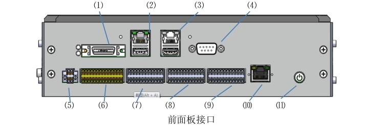
No. |
Interface Name |
No. |
Interface Name |
|---|---|---|---|
1 |
VGA&COM3/4 |
2 |
LAN1+USB3.0 |
3 |
LAN2+USB2.0 |
4 |
COM1 |
5 |
IO POWER (IO Power Supply) |
6 |
SIO (Safety IO) |
7 |
DIO (Digital IO) |
8 |
CIO (Configurable IO) |
9 |
EIO (Function Expansion IO) |
10 |
EtherCAT2 |
11 |
ON/OFF (Power On/Off) |

No. |
Interface Name |
No. |
Interface Name |
|---|---|---|---|
1 |
TP (Teach Pendant IO) |
2 |
Grounding |

No. |
Interface Name |
No. |
Interface Name |
|---|---|---|---|
1 |
24V_INPUT |
2 |
FAN(fan) |
3 |
EtherCAT1 |
4 |
48V_OUTPUT |
5 |
TR(brake resistor) |
6 |
48V_INPUT |
Figure 6 Interface Diagram of DC00 Controller (Please refer to the actual product for the panel version)
TP Interface#
The TP (Teach Pendant IO) interface is used to interact with the teach pendant junction box for signals such as the teach pendant’s emergency stop, enable, mode selection, and illuminated power on/off buttons. Its interface definition is shown in Table 9:
Table 9 Definition of TP Interface

Number |
Signal Definition |
Number |
Signal Definition |
|---|---|---|---|
1 |
EN1+ (Three-position Enable Input 1+) |
2 |
EN1- (Three-position Enable Input 1-) |
3 |
EN1+ (Three-position Enable Input 2+) |
4 |
EN2- (Three-position Enable Input 2-) |
5 |
SEL1+ (Mode Switch Input 1+) |
6 |
SEL1- (Mode Switch Input 1-) |
7 |
SEL2+ (Mode Switch Input 2+) |
8 |
SEL2- (Mode Switch Input 2-) |
9 |
EMG1+ (Teach Pendant Emergency Stop Input 1+) |
10 |
EMG1- (Teach Pendant Emergency Stop Input 1-) |
11 |
EMG2+ (Teach Pendant Emergency Stop Input 2+) |
12 |
EMG2- (Teach Pendant Emergency Stop Input 2-) |
13 |
PUSH+ (Illuminated Button Input +) |
14 |
PUSH- (Illuminated Button Input -) |
15 |
DC24V |
16 |
GND |
Note: This interface must be wired when in use; in WI-FI mode, the emergency stop button box wiring harness needs to be connected; in teach pendant mode, the teach pendant wiring harness needs to be connected; otherwise, an emergency stop will be triggered.
Grounding Interface#
This interface is connected to the PE wire, which is used to eliminate static electricity from the shell and protect the equipment as well as personal safety.
VGA & COM3, 4 Interfaces#
The VGA & COM3/4 interfaces are used for signals related to the display of the teach pendant screen and the operation of the teach pendant through the teach pendant junction box. Their interface definitions are shown in Table 10:
Table 10 Definitions of Teach Pendant VGA + 232 Interfaces

Number |
Signal Definition |
Number |
Signal Definition |
|---|---|---|---|
1 |
COM3_TX |
14 |
COM4_RX |
2 |
COM4_TX |
15 |
GND_ISO |
3 |
COM3_RX |
16 |
GND_ISO |
4 |
GND_ISO |
17 |
GND |
5 |
GND_ISO |
18 |
GND |
6 |
GND |
19 |
VGA_SCL |
7 |
GND |
20 |
VGA_SDA |
8 |
|
21 |
GND |
9 |
22 |
GND |
|
10 |
GND |
23 |
GND |
11 |
GND |
24 |
VGA_G |
12 |
VGA_B |
25 |
GND |
13 |
5V |
26 |
VGA_R |

LAN1 + USB3.0 Interface#
The LAN1 interface, with a speed of 1000M, supports PROFINET/MODBUS TCP/IP communication. It is used for communicating with other controllers and robots to realize robot control. It is a standard network cable interface, and its interface definition will not be listed here.
The USB3.0 interface is used to connect devices such as a mouse and keyboard, and also facilitates technicians to connect a USB flash drive for software copying. It is a standard USB3.0 interface, and its interface definition will not be listed here.
LAN2 + USB2.0 Interface#
The LAN2 interface, with a speed of 100M, supports MODBUS TCP/IP communication. It is used for communicating with other controllers and robots to realize robot control. It is a standard network cable interface, and its interface definition will not be listed here.
The USB2.0 interface is used to connect devices such as a mouse and keyboard, and also facilitates technicians to connect a USB flash drive for software copying. It is a standard USB2.0 interface, and its interface definition will not be listed here.
*If the customer selects a teach pendant, it will occupy the LAN2 interface for data transmission.

COM1 Interface#
The COM1 interface is an RS232 interface;
This interface is a DB9 female connector with male pins; its interface definition is shown in Table 11:
Table 11 Definition of COM1 Interface

Number |
Signal Definition |
Number |
Signal Definition |
|---|---|---|---|
1 |
NC |
2 |
COM1_RX |
3 |
COM1_TX |
4 |
NC |
5 |
GND_ISO |
6 |
NC |
7 |
NC |
8 |
NC |
9 |
NC |
IO POWER Interface#
The IO POWER (IO Power Supply) interface is used for power supply of SIO (Safety IO), DIO (Digital IO), CIO (Configurable IO) interfaces and internal circuits. The interface definition is shown in Table 12:
It is recommended that the wire harness here use 22AWG (0.2-0.3²) or smaller, with 8MM length tubular terminals.
Table 12 Definition of IO POWER Interface

Number |
Signal Definition |
Number |
Signal Definition |
|
1 |
Power (Controller 24V Output +) |
3 |
GND (Controller 24V Output -) |
|
2 |
DC24V (10 Power Supply Input +) | 4 |
0V (10 Power Supply Input -) |
||
Note: According to the power of the IO load, two power supply modes can be selected: internal power supply and external power supply.
For internal power supply, short-circuit pin 1 with pin 2, and pin 3 with pin 4; at this time, the internal will provide 24V DC with a maximum current of 2A (as shown in the figure).
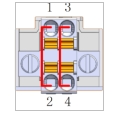
For external power supply, remove the shorting wire, connect pin 2 to an external DC24V power supply, and connect pin 4 to the 0V of the external power supply. In addition, short-circuit pin 3 with pin 4 for common grounding. After power supply is applied, the 0V of the external power supply will be connected to the 48V power supply ground of the system. Note that if the 0V of the external power supply used is short-circuited with the shell of the external power supply, the shell must not be connected to the system shell (PE) during installation. For external power supply, it can carry a maximum of 8A of 24V DC power (as shown in the figure). .. image:: ./image/16.jpg
- width:
120px


SIO Interface#
The SIO (Safety IO) interface is an external emergency stop and safety input/output interface provided by the controller, including 1 channel of user emergency stop signal input, 1 channel of system emergency stop feedback output, 1 channel of protective stop input, 2 channels of configurable safety inputs, and 2 channels of configurable safety outputs (all safety inputs and outputs are active signals).
Among them, the emergency stop signal input, protective stop input, and configurable safety inputs are dry contact interfaces;
When using the configurable safety outputs and system emergency stop feedback output, it is recommended to use solid-state relays for transfer. It is strongly recommended to use diode protection for inductive small relays.
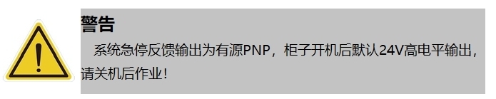
Note: The system emergency stop feedback output is defaulted to a high-level active output. Please note to operate after shutdown when wiring! Do not work with live electricity!
For the operation instructions of other interfaces for setting this interface through software, please refer to the Duco core User Manual. The interface definition is shown in Table 13:
Table 13 Definition of SIO Interface

Number |
Signal Definition |
Number |
Signal Definition |
|---|---|---|---|
1 |
EI1+ (User Emergency Stop Signal Input 1+) |
2 |
EI1- (User Emergency Stop Signal Input 1-) |
3 |
EI2+ (User Emergency Stop Signal Input 2+) |
4 |
EI2- (User Emergency Stop Signal Input 2-) |
5 |
PS1+ (Protective Stop Input 1+) |
6 |
PS1- (Protective Stop Input 1-) |
7 |
PS2+ (Protective Stop Input 2+) |
8 |
PS2- (Protective Stop Input 2-) |
9 |
CI1_1+ [Configurable Safety Input 1 (1+)] |
10 |
CI1_1- [Configurable Safety Input 1 (1-)] |
11 |
CI1_2+ [Configurable Safety Input 1 (2+)] |
12 |
CI1_2- [Configurable Safety Input 1 (2-)] |
13 |
CI2_1+ [Configurable Safety Input 2 (1+)] |
14 |
CI2_1- [Configurable Safety Input 2 (1-)] |
15 |
CI2_2+ [Configurable Safety Input 2 (2+)] |
16 |
CI2_2- [Configurable Safety Input 2 (2-)] |
17 |
EO1+ (System Emergency Stop Feedback Output 1+) (24V output by default) |
18 |
EO1- (System Emergency Stop Feedback Output 1-) |
19 |
EO2+ (System Emergency Stop Feedback Output 2+) (24V output by default) |
20 |
EO2- (System Emergency Stop Feedback Output 2-) |
21 |
CSO1_1+ [Configurable Safety Output 1 (1+)] |
22 |
CSO1_1- [Configurable Safety Output 1 (1-)] |
23 |
CSO1_2+ [Configurable Safety Output 1 (2+)] |
24 |
CSO1_2- [Configurable Safety Output 1 (2-)] |
25 |
CSO2_1+ [Configurable Safety Output 2 (1+)] |
26 |
CSO2_1- [Configurable Safety Output 2 (1-)] |
27 |
CSO2_2+ [Configurable Safety Output 2 (2+)] |
28 |
CSO2_2- [Configurable Safety Output 2 (2-)] |
SIO Interface Power Status Table:
SIO Interface |
220VAC Power-on |
Power-on State*1 |
Power-on & Power-off (Robot Arm) |
Open Configuration CSO |
EI*&CI* |
No Power |
24V |
24V |
24V |
EO* |
No Power |
24V |
24V |
24V |
CSO* |
No Power |
No Power |
No Power |
24V |
*1 The power-on state can be entered by pressing the power-on button on the teach pendant, the power-on button on the box, or via remote power on.
It is recommended that the wire harness here use 22AWG (0.2-0.3²) or smaller, with 8MM length tubular terminals.
The electrical parameters of the safety IO interface are shown in Table 14:
Table 14 Parameter Table of Safety IO Interface (PNP Type)
Safety DI |
||||
Terminal |
Parameter |
|||
EIx |
Dry contact input |
|||
PSIx |
Dry contact input |
|||
CSIx |
Dry contact input |
|||
Safety DO |
||||
Terminal |
Parameter |
Minimum |
Typical |
Maximum |
EOx/CSOx |
Current |
0A |
— |
0.2A |
Voltage |
23.52V |
24V |
25.2V |
|
Signal Type |
PNP |
|||
The timing diagram of Safety DI is shown in Figure 8:

Figure 8 Timing Diagram of Safety Input
The diagnostic pulse at the Safety DI input end is shown in Figure 7. The MCU checks whether the hardware circuit is faulty by sending diagnostic pulses. The diagnostic pulse has a period of 20ms and a negative pulse width of 500 (±100) μs.
The timing of Safety DO is shown in Figure 9:
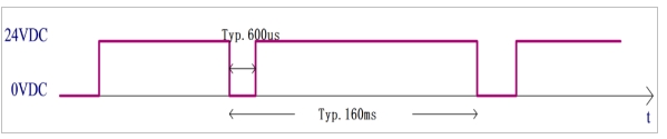
Figure 9 Timing Diagram of Safety Output
The diagnostic pulse at the output end of the Safety DO output is shown in Figure 8. The output control signal sent by the MCU contains a diagnostic pulse signal, with a diagnostic pulse period of 160ms and a negative pulse width of 600 (±100) μs.
Wiring Diagrams of SIO Interface#
Default Safety Configuration
Figure 10 shows the wiring diagram for the default configuration of the safety interface, which allows robot operation without any additional safety equipment.

Figure 10 Wiring Diagram for Default Safety Configuration
Connecting External Safety Input Signals
Figure 11 shows the wiring diagram for connecting external safety input signals to the safety input interface. Note that the external safety input signals are dry contact signals, and the emergency stop button is taken as an example of the external safety input signal.

Figure 11 Wiring Diagram for External Safety Signal Input
Connecting Protective Stop Signals
Figure 12 shows the wiring diagram for protective stop input signals. Note that the external protective stop input signals are dry contact signals.

Figure 12 Wiring Diagram for Protective Stop Signal Input
Connecting Configurable Safety Input Signals
The wiring diagram for configurable safety input signals is similar to that for protective stop input signals.
Sharing Emergency Stop with Other Machines
When robots are used in conjunction with other machines, it is often necessary to set up a common emergency stop circuit. By setting up a common line, operators do not have to think about which emergency stop button to use.
Since both machines need to wait for each other to exit the emergency stop condition, the standard robot emergency stop input cannot be used for sharing. To share the emergency stop function with other machines, it must be configured through the safety inputs and safety outputs of the controller’s safety IO.
In addition, the safety output is an active signal and must be used after being transferred through a solid-state relay, as shown in Figure 13:

Figure 13 Schematic Diagram of Emergency Stop Cascading for Two Robot Controllers
DIO Interface#
The DIO (Digital IO) interface provided by the controller includes 8 channels of digital input (DI) interfaces and 8 channels of digital output (DO) interfaces. The interface definitions are shown in Table 15:
It is recommended that the wire harness here use 22AWG (0.2-0.3²) or smaller, with 8MM length tubular terminals;
Table 15 Definition of DIO Interface

Number |
Signal Definition |
Number |
Signal Definition |
|---|---|---|---|
1 |
24V |
2 |
0V |
3 |
24V |
4 |
0V |
5 |
DI1 (General DI Input 1) |
6 |
DO1 (General DO Output 1) |
7 |
DI2 (General DI Input 2) |
8 |
DO2 (General DO Output 2) |
9 |
DI3 (General DI Input 3) |
10 |
DO3 (General DO Output 3) |
11 |
DI4 (General DI Input 4) |
12 |
DO4 (General DO Output 4) |
13 |
DI5 (General DI Input 5) |
14 |
DO5 (General DO Output 5) |
15 |
DI6 (General DI Input 6) |
16 |
DO6 (General DO Output 6) |
17 |
DI7 (General DI Input 7) |
18 |
DO7 (General DO Output 7) |
19 |
DI8 (General DI Input 8) |
20 |
DO8 (General DO Output 8) |
21 |
24V |
22 |
0V |
23 |
24V |
24 |
0V |
Digital Input (DI)#
The digital input (DI) interface provided by the controller has an input voltage range of: -3-30VDC (0~15mA). The electrical parameters of the interface are shown in Table 16:
Table 16 Parameter Table of DI Interface (PNP Type)
Terminal |
Parameter |
Minimum |
Typical |
Maximum |
Digital Input |
||||
DIX-24V |
Voltage |
-3V |
—— |
30V |
DIX-24V |
ON Region |
11V |
—— |
30V |
DIX-24V |
OFF Region |
-3V |
—— |
5V |
DIX-24V |
TON/TOFF Delay |
TON:50ms TOFF: 50ms |
||
DIX-24V |
Function |
PNP Type |
||
Dry contact signal input
Figure 14 shows the wiring method between the dry contact signal (button) and the DI port.

Figure 14 Wiring Diagram for Dry Contact Signal Input
PNP signal input
Figure 15 shows the wiring method between the PNP signal (output from the DO port of PLC, PNP type) input and the DI port.

Figure 15 Wiring Diagram for PNP Signal Input
Digital Output (DO)#
The digital output (DO) interface provided by the controller has an output voltage range of 23.52-25.2VDC, a maximum current of 0.5A, and switch time. The electrical parameters of the interface are shown in Table 17:
Table 17 Parameter Table of DO Interface (PNP Type)
Terminal |
Parameter |
Minimum |
Typical |
Maximum |
Digital Output |
||||
DOX-0V |
Current |
0A |
—— |
0.5A |
DOX-0V |
Voltage |
23.52V |
—— |
25.2V |
DOX-0V |
TON/TOFF Delay |
TON:50ms TOFF: 50ms |
||
DOX-0V |
Function |
PNP Type |
||
DO Output Connected to Load
Figure 16 shows the wiring diagram for the DO output directly connected to a load (relay), with a maximum output current of 0.5A.

Figure 16 Reference Wiring Diagram for DO Output and Load
Wiring Diagram for DO Output and Other PNP Input Devices
Figure 17 shows the wiring diagram between the DO port output and other PNP-type DI input devices (PLC):

Figure 17 Wiring Diagram for Connection with Other PNP-type DI Input Devices
CIO Interface#
The CIO (Configurable Digital IO) interface provided by the controller includes 8 channels of configurable digital input (DI) interfaces and 8 channels of configurable digital output (DO) interfaces; this interface can be configured as user DIO or functional DIO through software operations, and it is set as user DIO by default; its interface definitions are shown in Table 18:
It is recommended that the wire harness here use 22AWG (0.2-0.3²) or smaller, with 8MM length tubular terminals;
Table 18 Definition of Configurable Digital IO Interface

Number |
Signal Definition |
Number |
Signal Definition |
|---|---|---|---|
1 |
24V |
2 |
0V |
3 |
24V |
4 |
0V |
5 |
CDI1 (Configurable DI Input 1) |
6 |
CDO1 (Configurable DO Output 1) |
7 |
CDI2 (Configurable DI Input 2) |
8 |
CDO2 (Configurable DO Output 2) |
9 |
CDI3 (Configurable DI Input 3) |
10 |
CDO3 (Configurable DO Output 3) |
11 |
CDI4 (Configurable DI Input 4) |
12 |
CDO4 (Configurable DO Output 4) |
13 |
CDI5 (Configurable DI Input 5) |
14 |
CDO5 (Configurable DO Output 5) |
15 |
CDI6 (Configurable DI Input 6) |
16 |
CDO6 (Configurable DO Output 6) |
17 |
CDI7 (Configurable DI Input 7) |
18 |
CDO7 (Configurable DO Output 7) |
19 |
CDI8 (Configurable DI Input 8) |
20 |
CDO8 (Configurable DO Output 8) |
21 |
24V |
22 |
0V |
23 |
24V |
24 |
0V |
Note: For instructions on configuring this interface as user DIO or functional DIO through software, please refer to the Duco core User Manual.
Configurable Digital Input (CDI)#
The configurable digital input (CDI) interface provided by the controller has an input voltage range of: -3-30VDC (0~15mA).
For the interface parameter table, timing diagram, and wiring method, please refer to the description in the chapter 4.10.1 Digital Input (DI).
Configurable Digital Output (CDO)#
The configurable digital output (CDO) interface provided by the controller has an output voltage range of 23.52-25.2VDC and a maximum current of 0.5A.
For the interface parameter table, timing diagram, and wiring method, please refer to the description in the chapter 4.10.2 Digital Output (DO).
EIO Interface#
The EIO (Functional Expansion IO) interface of the DC00 controller is an interface provided by the controller for the outside, including 2 channels of voltage analog input interfaces, 2 channels of voltage analog output interfaces, 1 channel of external CAN communication interface, 1 channel of external RS485 communication interface, an INC encoder differential signal interface, and 1 channel of remote up/down point interface. Its interface definitions are shown in Table 19:
It is recommended that the wire harness here use 22AWG (0.2-0.3²) or smaller, with 8MM length tubular terminals;
Note: If the 24V power supply of the INC encoder is short-circuited, it may cause damage to the slave interface board. Avoid short circuits during use.
Table 19 Definition of Functional Expansion 1 Interface

Number |
Signal Definition |
Number |
Signal Definition |
|---|---|---|---|
1 |
AI1 (Voltage Analog Input 1) |
2 |
AG (Analog Ground) |
3 |
AI2 (Voltage Analog Input 2) |
4 |
AG (Analog Ground) |
5 |
AO1 (Voltage Analog Output 1) |
6 |
AG (Analog Ground) |
7 |
AO2 (Voltage Analog Output 2) |
8 |
AG (Analog Ground) |
9 |
24VE |
10 |
RC1 (Remote Switch ON+) |
11 |
GND |
12 |
PowerON (Remote Switch ON-) |
13 |
A+ (INC Signal Phase A+) |
14 |
RC2 (Remote Switch OFF+) |
15 |
A- (INC Signal Phase A-) |
16 |
PowerOFF (Remote Switch OFF-) |
17 |
A- (INC Signal Phase A-) |
18 |
CAN_L |
19 |
B- (INC Signal Phase B-) |
20 |
CAN_H |
21 |
Z+ (INC Signal Phase C+) |
22 |
485_B |
23 |
Z- (INC Signal Phase C-) |
24 |
485_A |
Voltage Analog Interface#
Voltage Analog Input (0~10V ±1%)
The voltage analog input is factory-set to a default 0-10V voltage input (with an accuracy of ±1%);
Voltage Analog Output (0~10V, ±1%)
The voltage analog output is factory-set to a default 0V voltage output;
Analog Signal Isolation Specifications
Analog signals are electrically isolated from each other, and the electrical specifications refer to Table 20:
Table 20 Analog Electrical Specifications
Terminal |
Parameter |
Minimum |
Typical |
Maximum |
Voltage Analog Input |
||||
AI_VX-AGND |
Voltage |
0V±1% |
—— |
10V±1% |
Resistance |
— |
48kΩ |
— |
|
Resolution |
— |
12 bits |
— |
|
Analog Wiring Diagram
Figure 18 shows the schematic diagram of analog interface wiring:

Figure 18 Schematic Diagram of Analog Input Wiring
Communication Interfaces (CAN, RS485, INC Signals)#
The external communication interfaces are signal-isolated from each other, and the communication parameter specifications refer to Table 21:
Table 21 Communication Specifications of Communication Parameters
Terminal |
Parameter |
Data |
CAN Communication |
Baud Rate |
10k, 20k, 50k, 100k, 125k, 250k, 500k, 1000k bps |
RS485 Communication |
Baud Rate |
4800, 9600, 19200, 38400, 115200 bps |
Line Impedance |
120Ω |
|
|
Supply Voltage |
24VDC |
Allowed Frequency |
<200KHz |
|
Input Signal |
Square Wave Signal (Compatible with Single-Ended/Differential) |
INC Interface Description#
Before wiring the INC, it is necessary to first check the form of the output circuit of the INC encoder. The following are examples of wiring methods for several common output forms:

Remote Switch Interface#
Using the remote switch, the system can be turned on or off without using the power-on button on the teach pendant or controller panel.
The “PowerON” input works on the same principle as the power-on button. It is essential to use the “PowerOFF” input for remote shutdown. This signal allows the controller to save open files and shut down normally (similar to a system soft shutdown).
The definition of the remote switch interface is shown in Table 22:
表22 远程开关接口定义
Connector Number |
Signal Definition |
Input Signal Type |
10 |
RC1 |
Dry Contact |
12 |
PowerON |
|
14 |
RC2 |
Dry Contact |
16 |
PowerOFF |
The electrical specifications are as shown in Table 23:
Table 23 Electrical Specifications of Remote Switch Interface
Terminal |
Parameter |
Minimum |
Maximum |
PowerON-RC1 |
Voltage |
0VDC |
25.2VDC |
PowerOFF -RC2 |
Voltage |
0VDC |
25.2VDC |
PowerON Activation Time |
>1S |
||
PowerOFF Shutdown Time |
>3S |
||
The wiring method for the remote switch is as follows:
Remote PowerON Interface (Dry Contact Input)
Figure 21 shows the wiring method for the remote PowerON button, where a self-resetting button is used.

Figure 21 Schematic Diagram of Remote Power-On Wiring
Remote PowerOFF Interface (Dry Contact Input)
Figure 22 shows the wiring method for the remote PowerOFF button, where a self-resetting button is used.

Figure 22 Schematic Diagram of Remote Power-Off Wiring
EtherCAT2 Interface#
The EtherCAT2 interface supports EtherCAT communication; it is reserved for backup use. It is a standard network cable interface, and the interface definition is not listed here.

24V_INPUT Interface#
The 24V_INPUT interface is a DC24V power supply provided by the 48V-to-24V isolation module. In addition to supplying power to the main controller at the MCU end of the DC00 controller, it also supplies power to the RC (internal interface), IO interface, TP teach pendant, and fan respectively after being controlled by the MCU. The interface definition is shown in Table 24:
Table 24 Definition of 24V_INPUT Interface

Number |
Signal Definition |
Number |
Signal Definition |
1 |
|
2 |
|
FAN Interface#
The FAN (fan) interface is used to supply driving current to the DC fan (without frequency conversion); the output voltage of this port is DC24V, the maximum output current is 2A, and it is recommended to use a DC fan with a power of 5~10W; its interface definition is shown in Table 25:
Table 25 Definition of FAN Interface
Number |
Signal Definition |
Number |
Signal Definition |
1 |
DC24V |
2 |
GND |
EtherCAT 1 Interface#
The EtherCAT 1 interface is specifically used for communication and interaction with the robotic arm; its interface definition is shown in Table 26:
Table 26 Definition of Ecat OUT1 Interface

Number |
Signal Definition |
Number |
Signal Definition |
1 |
TX+ |
2 |
TX- |
3 |
RX+ |
4 |
RX- |
48V_OUTPUT Interface#
The 48V_OUTPUT interface is specifically used to provide DC48V power for the robotic arm, and its interface definition is shown in Table 27:
Table 27 Definition of DC48V Output Interface

Number |
Signal Definition |
Number |
Signal Definition |
1 |
48V+ |
2 |
48V- |
3 |
PE |
TR Interface#
The TR interface is connected to the braking resistor; when the direction of the motor’s output torque is opposite to that of its rotational speed, it indicates that energy is transmitted back from the load end to the driver. This energy feedback causes the voltage to rise. When it rises to a certain value, the feedback energy can only be consumed by the braking resistor. The definition of this interface is shown in Table 28:
The standard braking resistor is 150W, 3Ω.
Table 28 Definition of Braking Resistor Interface

Number |
Signal Definition |
Number |
Signal Definition |
1 |
R+ |
2 |
R- |
48V_INPUT Interface#
The 48V_INPUT interface is specifically used to provide DC48V power for the robotic arm; its interface definition is shown in Table 29:
Table 29 Definition of DC48V Input Interface

Number |
Signal Definition |
Number |
Signal Definition |
1 |
48V+ |
2 |
0V |