


Overview#
This paper introduces important information of safety function and risk assessment, which must be read and understood by the user before the robot is powered on for the first time.
Before performing any operation, ensure that you have read all the operation instructions provided with the device, especially the dangers, warnings, and precautions that may endanger the safety of the human body and the device to minimize the chance of accidents. If this document is different from the document delivered with the device, the document delivered with the device shall prevail.
The personnel responsible for the installation and maintenance of the equipment must be trained professionals who have mastered the proper operation methods and all safety precautions. Only trained and qualified personnel are allowed to install and maintain devices.
Effective scope and responsibility statement#
This information does not include how to design, install and operate a complete robot system, nor does it include all peripherals that can affect the safety of the entire system. In order to protect human safety, the system must be well designed and must be installed in accordance with the safety requirements specified in the standards and regulations of the country in which the robot is installed.
The robot integrator shall be responsible for ensuring that the robot system complies with the applicable safety laws and regulations of the country or region in which it is located, and that the necessary safety equipment to protect the operator of the robot system is properly designed and installed.
The details include but are not limited to the following:
Ensure that robot systems meet all basic requirements;
Perform a risk assessment of the complete system;
Ensure the design and installation of the entire system is accurate;
Make appropriate safety settings in the software and ensure that they are not modified by users;
Formulate detailed operating instructions;
Issue a declaration of conformity;
Collect all information in technical documents;
Label the installed robot system with the integrator’s logo and contact information;
Siasun Co., Ltd. is committed to providing reliable safety information, for which it shall not be liable unless it has been willfully or grossly negligent in providing reliable safety information. It should be made clear that even if everything is operated in accordance with safe practices, there is no guarantee that the robotic system will not cause damage to the user’s person or property.
Siasun Co., Ltd. will not be liable for user losses caused by the following reasons:
Force majeure events (e.g. natural disasters, fires, wars, etc.);
Natural damage or wear of the robot system;
The field operating environment (for example, voltage, temperature, humidity, etc.) or external factors (for example, external interference, etc.) cannot meet the environmental requirements for normal operation that have been prompted;
The robot system is not installed correctly (including not re-installed correctly after relocation);
Due to intentional or negligent use by the User or a third party, improper use (including the user’s failure to use in accordance with this User manual and/or other requirements of Siasun) or sabotage.
Unless otherwise agreed, the company shall not be liable for indirect, special or incidental losses caused by the use of the robot system, including but not limited to loss of revenue, loss of actual or expected earnings, loss of business, loss of opportunity, loss of goodwill, loss of reputation, loss of data, damage or disclosure.
Reference Standard#
The standard referenced for the design, development, and validation of the GCR series robots are as follows:
Standard number |
Definition |
|---|---|
ISO 10218-1:2011 |
Robots and robotic devices — Safety requirements for industrial robots — Part 1: Robots |
IEC 60204-1: 2016 |
Safety of Machinery – Electrical equipment of machines – Part 1: General requirements |
ISO 13849-1:2023 |
Safety of machinery — Safety-related parts of control systems —Part 1:General principles for design |
IEC/EN 62061: 2021 |
Safety of machinery – Functional safety of safety-related electrical, electronic and programmable electronic control systems |
IEC 61800-5-2: 2022 |
Adjustable speed electrical power drive systems – Parts 5-2, Safety requirements - functional |
IEC 61784-3: 2021 |
Industrial communication networks – Profiles – Part3: Functional safety fieldbuses – General rules and profile definitions. |
IEC 61508-1:2010 |
Functional safety of electrical/electronic/programmable electronic safety-related systems - Part 1: General requirements |
IEC 61508-2:2010 |
Functional safety of electrical/electronic/programmable electronic safety - related systems - Part 2: Requirements for electrical / electronic / programmable electronic safety-related systems |
IEC 61508-3:2010 |
Functional safety of electrical/electronic/programmable electronic safety-related systems - Part 3:Software requirements |
IEC 61508-4:2010 |
Functional safety of electrical/electronic/programmable electronic safety-related systems - Part 4:Definitions and abbreviations |
IEC 60664-1:2020 |
Insulation coordination for equipment within low-voltage supply systems – Part 1: Principles, requirements and tests |
IEC 61000-6-2: 2016 |
Electromagnetic compatibility (EMC) Part 6-2: Generic standards - Immunity for industrial environments |
IEC 61000-6-4: 2018 |
Electromagnetic compatibility (EMC) Part 6-4: Generic standards - Emission standard for industrial environments |
IEC 61000-6-7: 2014 |
Electromagnetic compatibility (EMC) - Part 6-7: Generic standards – Immunity requirements for equipment intend to perform functions in a safety-related system (functional safety) in industry locations. |
IEC 61326-3-1:2017 |
Electrical equipment for measurement, control and laboratory use – EMC requirements – Part 3-1: Immunity requirements for safety-related systems and for equipment intended to perform safety-related functions (functional safety) General industrial applications. |
Risk Assessment#
Risk assessment is one of the most important tasks that an integrator must perform. The robot itself is a partially completed machine, and the safety of the robot installation depends on how the robot is integrated (e.g. TCPs, obstacles, and other machinery).
Integrators are advised to perform risk assessments in accordance with standards ISO12100 and ISO10218-2. Alternatively, the technical specification ISO/TS 15066 can be selected as additional guidance. Integrators performing risk assessments should consider all work procedures throughout the robot’s application life, including but not limited to:
Demonstrating the robot while developing a robot installation
Fault diagnosis and maintenance;
Normal operation of robot installation.
The risk assessment must be carried out before the robot is powered on for the first time. Part of the risk assessment performed by the integrator is to identify the correct safety configuration Settings and determine whether additional emergency stop buttons and other protective measures are required.
The following identifies the major risks that integrators must consider. Please note that there may be other significant hazards associated with a particular robot device.
The finger is sandwiched between joint 4 and joint 5 of the robot.
Sharp edges and sharp points on TCPs or TCP connectors puncture the skin.
Sharp edges and sharp points on obstacles near the robot’s trajectory puncture the skin.
Sprains or fractures due to impact between the robot payload and a solid surface.
Consequences of loose bolts used to hold the robot or TCP in place.
Items fall off the TCP, for example due to improper clamping or power failure.
Operation errors due to different emergency stop buttons on different machines.
If the robot is installed in a non-collaborative robot application where the risk cannot be adequately eliminated using its internal safety features, such as the use of hazardous TCPs, the system integrator must install additional protection based on the risk assessment (for example, using protection that can protect the integrator during installation and programming). Due to the failure to install protective devices caused by the loss, Siasun Co., Ltd. will not be responsible for this.
Risks and countermeasures#
Clamp injury and collision risk#
There are still blind spots in the collision detection function during the actual operation of the robot, and users must pay attention to the risk of collision detection failure or clamp injury under special working conditions. Three typical working conditions are described below. Taking GCR30-1100 as an example, other arm types are converted proportionally.
Working condition 1: When the end position of the robot is more than 1000mm away from the center of the robot base, if the robot moves in the direction of the red arrow as shown in Figure 1‑1 and Figure 1‑2, the robot is less sensitive to external forces in the direction of movement, and is more prone to the risk of clamping injury. When the robot moves in the direction of the green arrow as shown in Figure 1‑1 and Figure 1‑2, if the robot collides with the external environment, it will be sensitive to the external force caused by the collision.

Figure 1‑1 Front view of robot under working condition 1
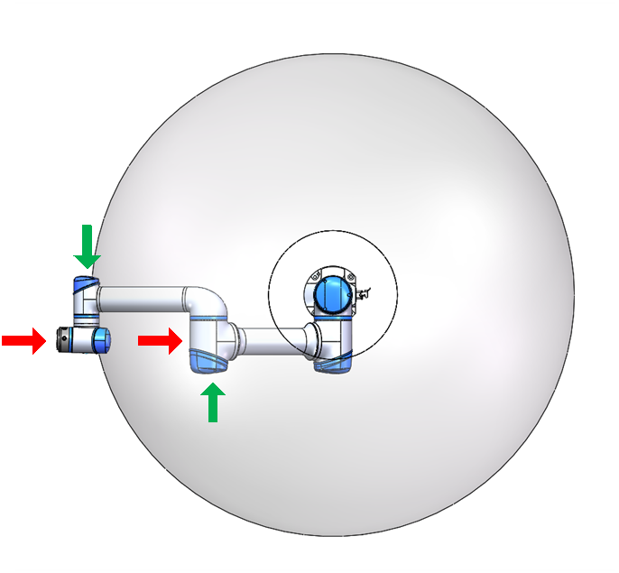
Figure 1‑2 Top view of robot under working condition1
Working condition 2: With the Z direction of the robot base as the center and the radius of about 350mm, if the contact point is within this range and the direction of the contact force is perpendicular to the plane where the connecting rod of joint 2 and joint 3 is located, the collision detection function is difficult to detect the collision between the robot and the outside world. The red arrows in Figure 1‑3 and Figure 1‑4 are shown; At this time, if the direction of the contact force between the robot and the outside world is more consistent with the direction of the base mark Z, the robot is more sensitive to the external force generated by the collision, as shown by the green arrow in Figure 1‑3.

Figure 1‑3 Front view of robot under working condition 2

Figure 1‑4 Top view of robot under working condition 2
Working condition 3: No matter what pose and motion state the robot is in, when the robot collides with the outside world, if the collision point is centered on the origin of the robot’s base position and the radius is about 350mm, it is difficult for the robot to detect this kind of collision, and the danger of nip injury is more likely to occur, as shown by the red arrow in Figure 1‑5 and Figure 1‑6. When the collision point is outside the range and does not meet the collision detection blind zone conditions described in working conditions 1 and 2, the robot is easier to detect the collision with the outside world, as shown by the green arrow in Figure 1‑5 and Figure 1‑6.

Figure 1‑5 Three-side view of robot under working condition 3
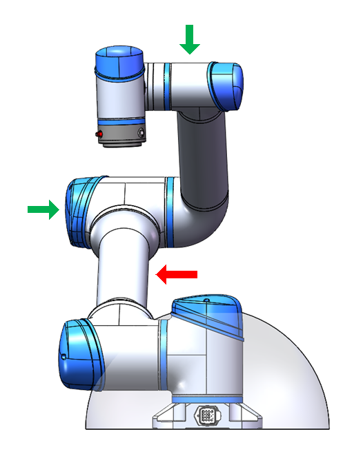
Figure 1‑6 Three positive view of robot under working condition 3
For all the above described working conditions, if the robot moves in a direction that is not sensitive to external collision detection, the operating speed should be reduced as much as possible, taking into account the limited needs of the robot’s cooperation with the outside world.
Manual release brake#
When the nip accident unfortunately occurs, it is able to use the manual release brake function to reduce the loss caused by the accident. When the robot is powered on but not enabled, starting “Manual release lock function” at the lower left corner of the interface. After clicking the “manual release brake” button, the interface will switch as shown in the Figure 1‑7 below:
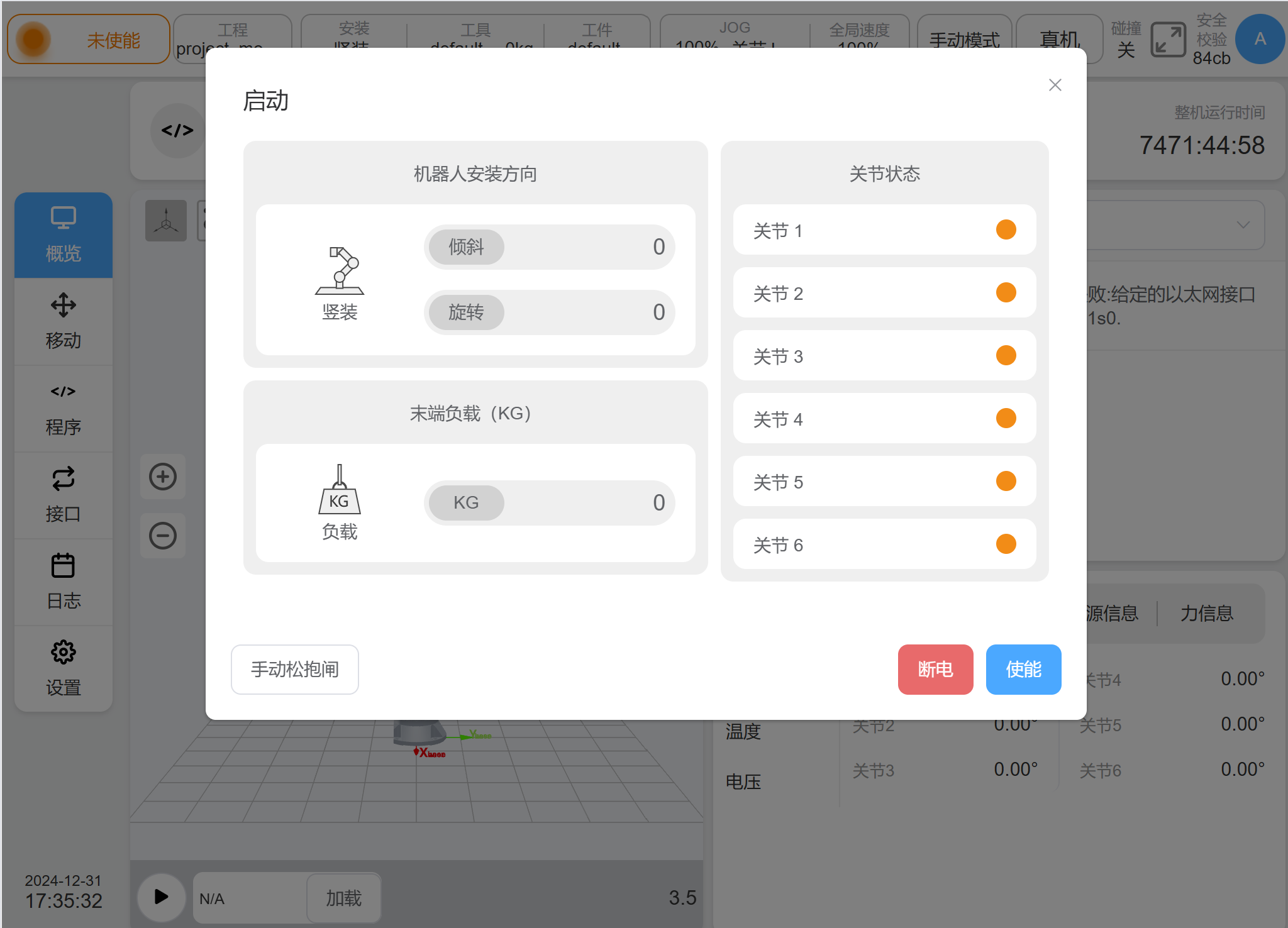
Figure 1‑7 Starting interface for manual release brake#
Click the “release lock” button to release the lock of the corresponding joint and allow the joint to be driven without power. The red indicator on the left of the interface indicates the lock status. Click “close lock gate” button to re-close the lock gate of the corresponding joint shown in Figure 1‑8
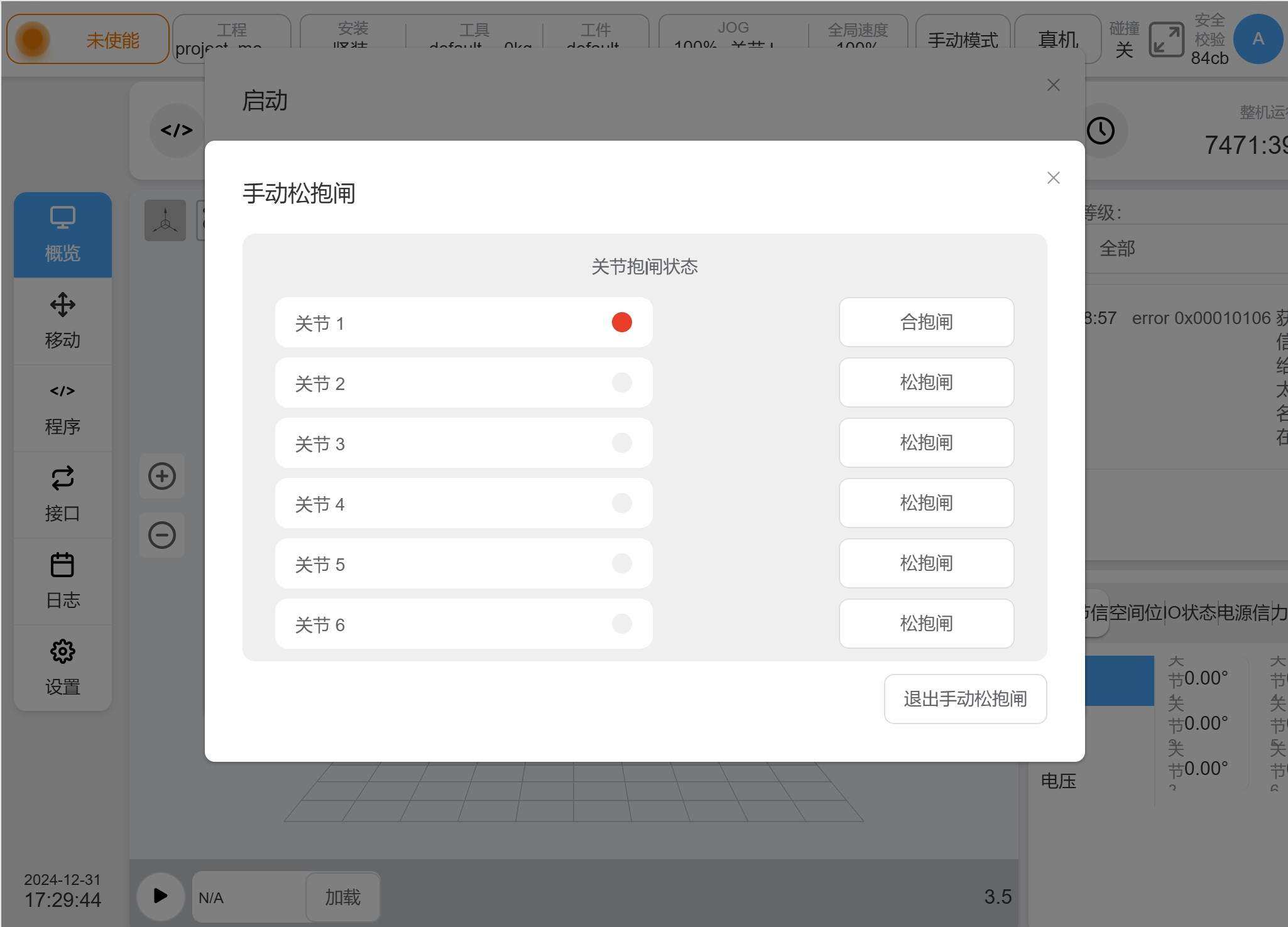
Figure 1‑8 Interface for manual release brake#
Robotic Singularity Stall Risk#
The robot automatically decelerates when motion planning (straight line, arc, etc., excluding articulated motions) is performed near singularities, and should be taught to avoid singularities or pass through singularities with articulated motions. For the GCR series configuration, there are shoulder singularities, elbow singularities, and wrist singularities.
Shoulder Singularity#
When the center of the wrist joint (the intersection of the axis of joint J5 and joint J6) is on the axis of joint J1, the shoulder singularity is caused at this time, resulting in no solution to the joint 1. A singular effect is also experienced when O6 is located very close to J1, where moving the extremity may cause joint 1 overdrive. Refer to the figure below Figure 1‑9.
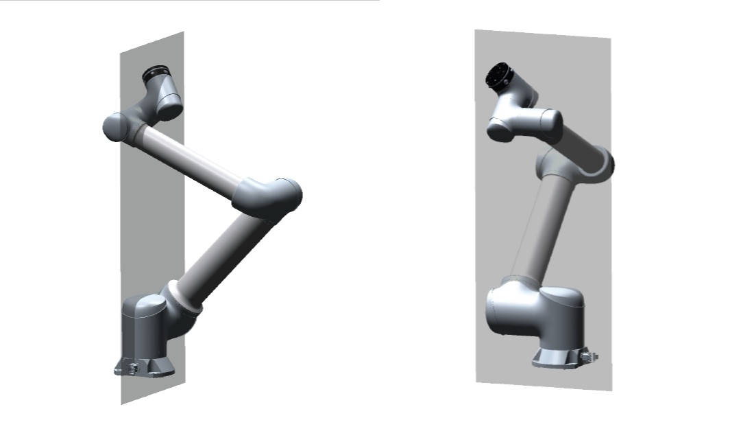
Figure 1‑9 Shoulder singular reference pose#
Elbow singularity#
When joint 2, 3 and 4 axes J2, J3 and J4 are coplanar, there is no solution to the joint 2. As an example when joint 3 is in the near singular pose near 0 degrees, moving the end may cause joint 2, joint 3, and joint 4 to overdrive. Refer to the Figure 1‑10 below.
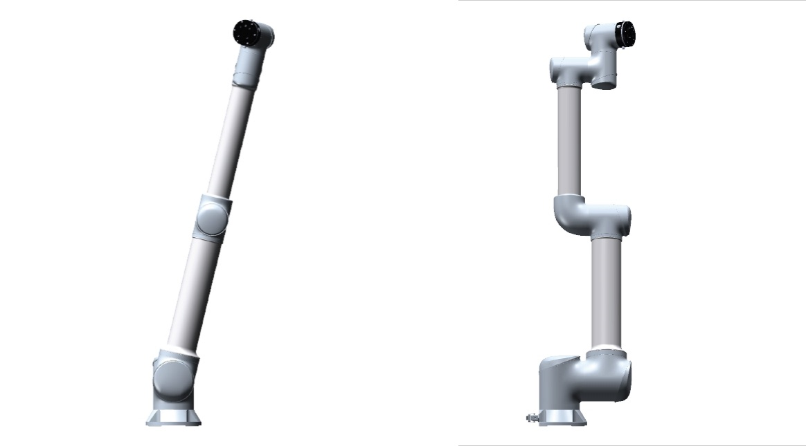
Figure 1‑10 Elbow singular reference pose#
Wrist Singularity#
When joint 5 is at 0 degrees or 180 degrees, there is no solution to joint 6, resulting in wrist singularity. When joint 5 is close to 0 degree, causing a near-wrist singular posture. In this case moving the extremity may cause the joint 4, joint 5 and joint 6 to over speed. Refer to the following Figure 1‑11.
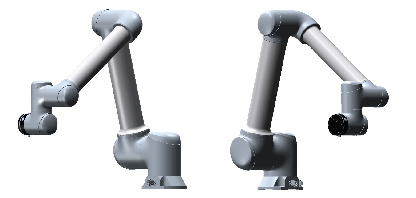
Figure 1‑11 Wrist singular reference pose#
When the robot runs to or near the above singular points, the planned motion based on Cartesian coordinates cannot be inversely solved to the joint motion of each axis, and the motion planning cannot be carried out correctly. The node motion or move j motion command can be adopted.
Warning
Please avoid using commands such as straight lines, arcs, moving the end along X, Y, Z, RX, RY, RZ directions that near singularities which may getting robot a risk of stalling.
Trajectories with singular risks must be fully safety assessed before they are run.
Emergency Stop#
Emergency stop is a condition that takes precedence over all other robot control operations and will result in all controlled hazardous stops, eliminate motor power from the robot drive, remain active until reset, and can only be restored by manual operation.
The emergency shutdown condition means that the power system is disconnected and the robot cannot move. The user must perform the restore step, that is, reset the emergency stop button and press the “Power on” button on the teach pendant to resume normal operation. Emergency downtime cannot be used as a risk reduction measure, but can be used as a secondary protection device.
Emergency shutdown should not be used for normal program stops, as this may cause additional unnecessary depletion on the robot.
Assumptions and Constraints#
Assumptions:
The safety control system is designed to comply with the related standards specified in Clause1.3
According to IEC 61508-2:2010 section 7.4.4.1.3, the GCR series Cobot system is type B.
The functional safety system fulfill Cat.3 PL d according to ISO 13849, and SIL 2 according to IEC 61508, with corresponding MTTFd,DC=Medium to high, HFT=1.Certain safety functions e.g. emergency stop, protective stop, safety brake control, STO, enabling device and mode selection, shall fulfill Cat.3 PL e according to ISO13849-1, and SIL 3 according to IEC61508.
If customers purchase DC00 controller for secondary system integration, the configured bulid-in power supply must be HWS600P-48. And should install the DC00 controller in an environment meet to IP54.
Before using the robot, the customer should conduct a risk assessment against the contents of the “Safety Manual” to confirm that the collision detection performance and magnetic environment meets its operating conditions
If the robot detects a malfunction or violation in the safety system (e.g. A line is cut in the emergency stop circuit or a safety limit violation occurs), a Class 0 stop will be initiated.
The use of safety configuration parameters that differ from those identified in the risk assessment can lead to hazards that cannot reasonably be eliminated or risks that cannot be adequately reduced
Ensure that the TCP and gripper are connected correctly to avoid hazards in the situation of a power interruption.
The function of end-effector is not protected by the GCR safety system. The connecting cable of the end-effector is not monitored.
Constraint:
System integration:
The factory configuration, the external emergency stop input is short circuited. Therefore, the external emergency stop function is bypass. The integrator should configure an external emergency stop button at first.
An emergency stop button which compliance to IEC 60947-5-5:2017 is demanded to apply as the external emergency stop button.
A dual channel button which compliance to IEC 60947-5-1:2009 is demanded to apply as the safety input button.
When the STO/SBC and SS1 function is triggered, the motion will deviate the trajectory expected, therefore the stop time and stop distance should be considered as part of the application risk assessment.
Due to the robotic arm structure or other reason, in some positions, the collision force will inevitably exceed the limit value shown in ISO 15066:2016 table A.2. The System integrator should verify/test collision force when they integrate the robot in application with actual working condition.
The collision force along the robot extension direction will always generate significant forces. During the integration, it is advisable to avoid collisions between operators and the robot in the extension direction as much as possible. If it cannot be avoided, it is necessary to reduce the speed or payload.
Electrical:
Since the safety signal is at a high level and normal, a low level is considered triggering. Under normal circumstances, there is a 24V output. Therefore, the system must be completely powered off before wiring.
Application:
Due to the physical characteristics of the robot and the realization principle of the collision detection function, there are still blind areas of the collision detection function during the actual operation of the robot. The blind areas of the collision detection function for each model needs refer to the safety manual.Pay attention to the risk of collision detection failure or pinch injury. Refer to the section 1.4.1
The cobot system cannot use in strong magnetic environment because the encoder of cobot is magnetic encoder. According to the technical data sheet of encoder, encoder will be damage if it working in magnetic fields higher than 50mT. As a matter of experience, if the magnetic field is 350mT at the surface of cobot, after attenuation, the magnetic fields is 8mT at the surface of encoder.
The use and configuration of safety functions and interfaces must follow the risk assessment procedure for each robot application
According our test result, the collision of upper arm is always dangerous. Therefore, do not touch the upper arm and close to the robot base during robot running.
The system integrators should re-verification the robot safety functions performance after re-configuration safety parameters.
Forbidden operate robot manually while using TP shielding port. Because the three-position enable function is bypass.
If the customer modifies the security parameters, they should double check the safety parameters before confirming the download. Refer to the section “Safety Parameters-Change and Application of Safety Parameters”.
Before the robot switch to auto mode, all persons should leave the robot’s motion space.
During programming, the operator must hold the teach pendant to enter the robot’s motion space.
If there is a sudden power-off in factory, should also press the emergency input button and turn-off the system rocker-switch.
Since the recording of the power-down position is cyclical, there is a probability that an accidental power failure during the movement of the arm will trigger an “abnormal movement occurred” error at the next power-up.
To ensure that the emergency stop function is always active, it is required that the arm be powered off and re-power on every 90 days to ensure that the safety controller carries out a functional check of this section of the electrical circuit. If this is not executed, the hardware integrity cannot reach SIL3.
To ensure that SS2/SOS function remain effective, the user should move the robot one time, if the robot stays at SS2/SOS state more than 24h.
Maintenance:
Ensure no objects on the fixture before maintenance.
At least two people are required to maintenance, with one person who is stayed outside the robot’s motion space, holding the emergency stop input to prevent accidents.
To ensure the safety function STO/SBC execute normally, the stop time and distance is normal. Users are required to perform a brake check on a regular basis to prevent the risk of the arm failing due to a brake failure. The system will remind the user of the need to carry out the brake test periodically, and the factory default is to remind the user every 30 days. Refer to <GCR series Cobot User Manual(Software)>