


Safety Parameters#
Viewing Safety Parameters#
Click the ‘Safety CRC’ button on the upper status bar to bring up the following dialog box to view the currently active Safety configuration parameters.
Alternatively, you can view the Safety configuration parameters in the Settings page - Safety Settings.
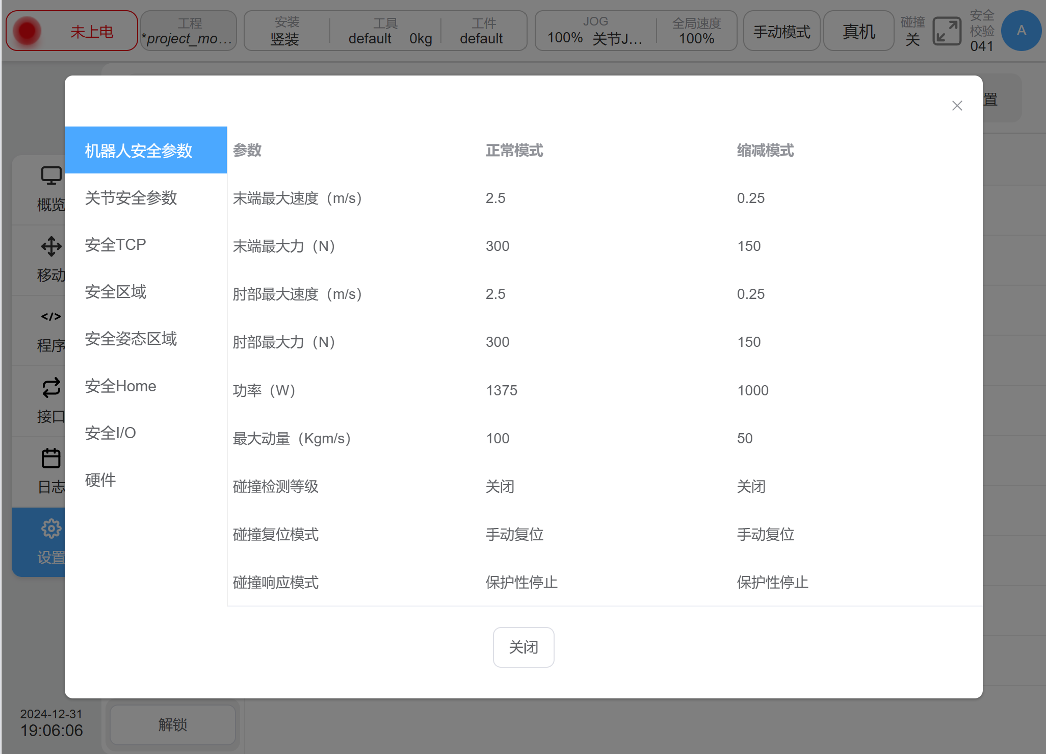
Figure 4‑1 view safety parameter#
Change and Application of Safety Parameters#
Before changing the Safety configuration, you must use the password to unlock the robot. Enter the Setup page - Safety Configuration, click the ‘Unlock’ button on the lower left, only in the case of “cut off the power supply of arm” can be unlocked, enter the password (the login password of the current logged-in user), and then enter the Safety parameter configuration mode after passing the verification. At this time, the status display area on the status bar shows ‘Safety Parameter Configuration’.
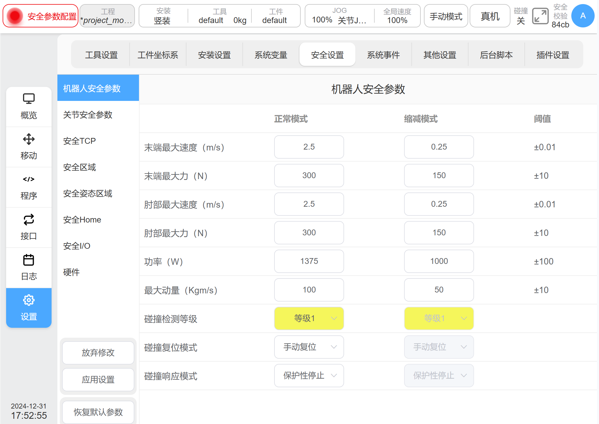
Figure 4‑2 safety parameters configuration#
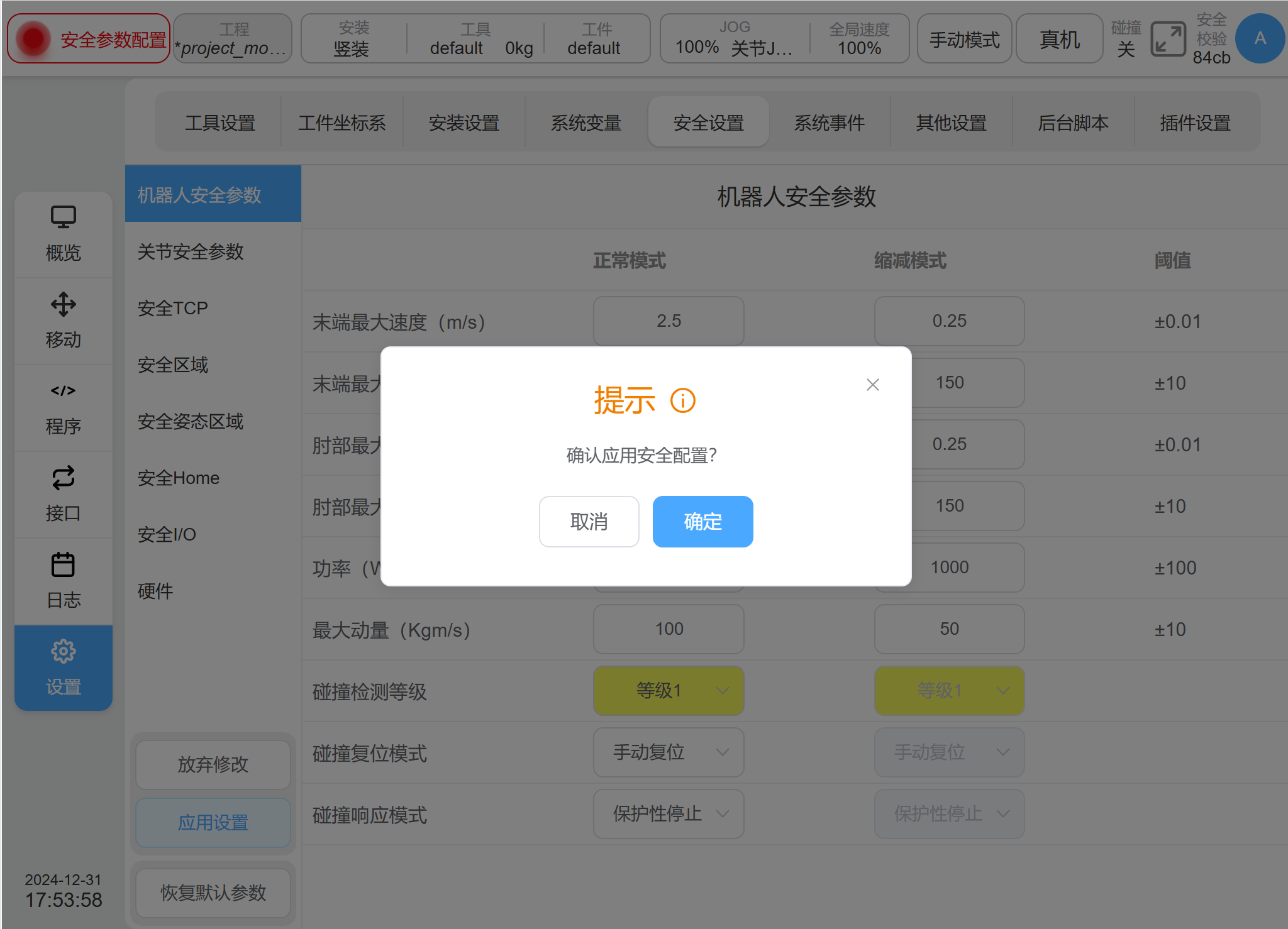
Figure 4‑3 confirm safety parameters#
After single clicking the ‘Confirm’ button, a prompt box for the process of loading Safety parameters will be displayed, as shown in the figure.
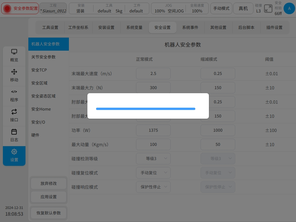
Figure 4‑4 downloading safety parameters#
After the Safety parameter configuration is completed, the system will display the configured Safety parameters again in a pop-up window for users to check. As shown in the figure below, after checking and confirming that there is no error, click the ‘OK’ button to configure the Safety parameters. After successful configuration, the Safety check at the top of the status bar will be changed.

Figure 4‑5 Verification safety parameters#
Robot Safety Parameters#
Robot parameters are used to limit general robot motion. It is able to configure its parameter values in normal and reduced modes.
Parameter |
Description |
|---|---|
TCP Maximum Speed |
Limit the maximum linear speed of robot safety tcp in space |
TCP Maximum Force |
Limit the maximum force by the robot safety tcp |
Elbow Maximum Speed |
Limit the maximum linear speed of the robot’s elbow in space |
Elbow Maximum Force |
Limit the maximum force by the robot’s elbow. |
Power |
Limit the maximum amount of mechanical power by the robot, with the robot payload considered part of the robot body |
Maximum Momentum |
Limit the maximum amount of momentum output by the robot, with the robot payload considered part of the robot body. |
Collision level |
Sensitivity of the robot to detect collisions with the outside world, the higher the level the higher the sensitivity (see section “Safety Functions-Collision Detect” for details). The system integrators can estimate the collision force quickly according to section “Safety Functions-Collision Detect- Collision Force Estimation” |
Collision response |
Switch which safety stop should trigger as the reaction after collision. Can setting as SS2 or STO. |
Warning
The system integrators should re-assess the robot collision detect performance after configuration.
Joint Safety Parameters#
Joint parameter limits are used to limit the minimum position, maximum position, velocity, and torque of each joint of the robot. It is able to configure their parameter values in normal and reduced modes.
Parameter |
Description |
|---|---|
Minimum Position |
Defines the minimum position of each joint. |
Maximum Position |
Defines the maximum position of each joint. |
Maximum Velocity |
Defines the maximum angular velocity of each joint. |
Maximum Torque |
Defines the maximum torque of each joint. |
Safety TCP#
The safety system can define three sets of TCP offsets, which, when configured, will be used by the robot for speed monitoring and position monitoring. Any one of the TCP position and speed exceeding the safety setting will trigger a safety violation.
Velocity monitoring is the maximum linear velocity of the robot’s safe TCP center in space in the ‘Robot Safety Parameters’, and position monitoring is the ‘Safe Area’. Three safe TCPs can be set, and there are two ways to define the TCPs, either by choosing the TCP coordinate system defined in the global variables, or by customizing the value of the input coordinate system. When a predefined TCP coordinate system is used, the TCP coordinate system is selected and the value of the TCP coordinate system is displayed in the X, Y, Z input box. If the X, Y, and Z values are modified, the coordinate system becomes customized. When Custom input data is selected, the values of X, Y, Z, Rx, Ry, Rz, and the radius of the envelope are edited directly.
Each safety TCP can be set: disabled, always active, auto mode active, safety combination configuration 1, safety combination configuration 2, five activation conditions. When all three TCPs are disabled, the safety control system uses the flange coordinate system by default, with a ball radius of 50 mm. on the TCP configuration list, the configuration status of the corresponding TCP is displayed, and the corresponding status is grayed out if a TCP is disabled.
Safety Zone#
Safety zone definition types include flat, rectangular and cylindrical forms. Users can set up to 6 mutually independent space zones.
The activation configurations of the safety zone are: disabled, always active, auto mode active, safety combination configuration 1, and safety combination configuration 2, overall 5 types.
Boundary response of the safety zone refers to the response when the robot enters the safety zone from the outside and exceeds the boundary in the internal movement, and there are two response modes, i.e.: limit exceeding the boundary, and entering the zone triggering reduce mode. When selecting Limit Exceeds Boundary, it describes the response when the robot exceeds the boundary in internal movement; when selecting Trigger Reduce Mode, it describes the response when the robot enters the zone from outside, and restores the normal mode when the robot leaves the zone. The spatial region can also be set to include an elbow restriction or not, and the spatial extent of the elbow is set in the form of a ball radius.
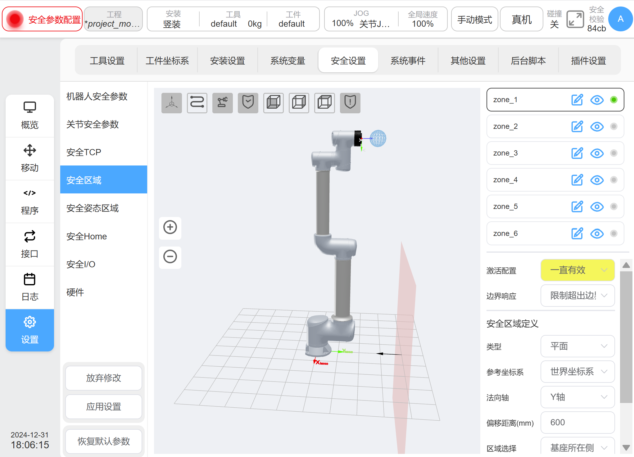
Figure 4‑6 Safety Area Maps in Plane#
When the configured area type is planar, the reference datum of the planar area is based on the world coordinate system/base/set work coordinate system, and the plane is determined by setting the plane normal direction and normal offset. The plane can be configured as an effective area by ‘Area Selection’, and the corresponding direction is displayed in the 3D area with a black arrow.
When the configured area type is Spatial Rectangle, the base of the rectangle area is based on the world coordinate system/base/work piece coordinate system, and the work piece coordinate system is used as a corner point of the rectangle, and the three coordinate axes correspond to the length (X), width (Y), and height (Z), respectively. The setting range of length, width and height is -3000mm-3000mm.
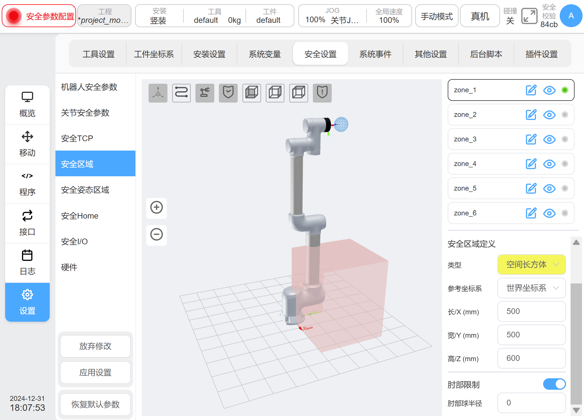
Figure 4‑7 Safety Area Maps in Space Rectangles#
When the configuration area type is spatial cylinder, its setting reference is based on the world coordinate system/base/set work piece coordinate system, with the work piece coordinate system as the center of the circular plane, and the Z direction pointing to the height direction, and you can set the radius and height. The range of radius is 0-3000mm and the range of height is -3000mm-3000mm.
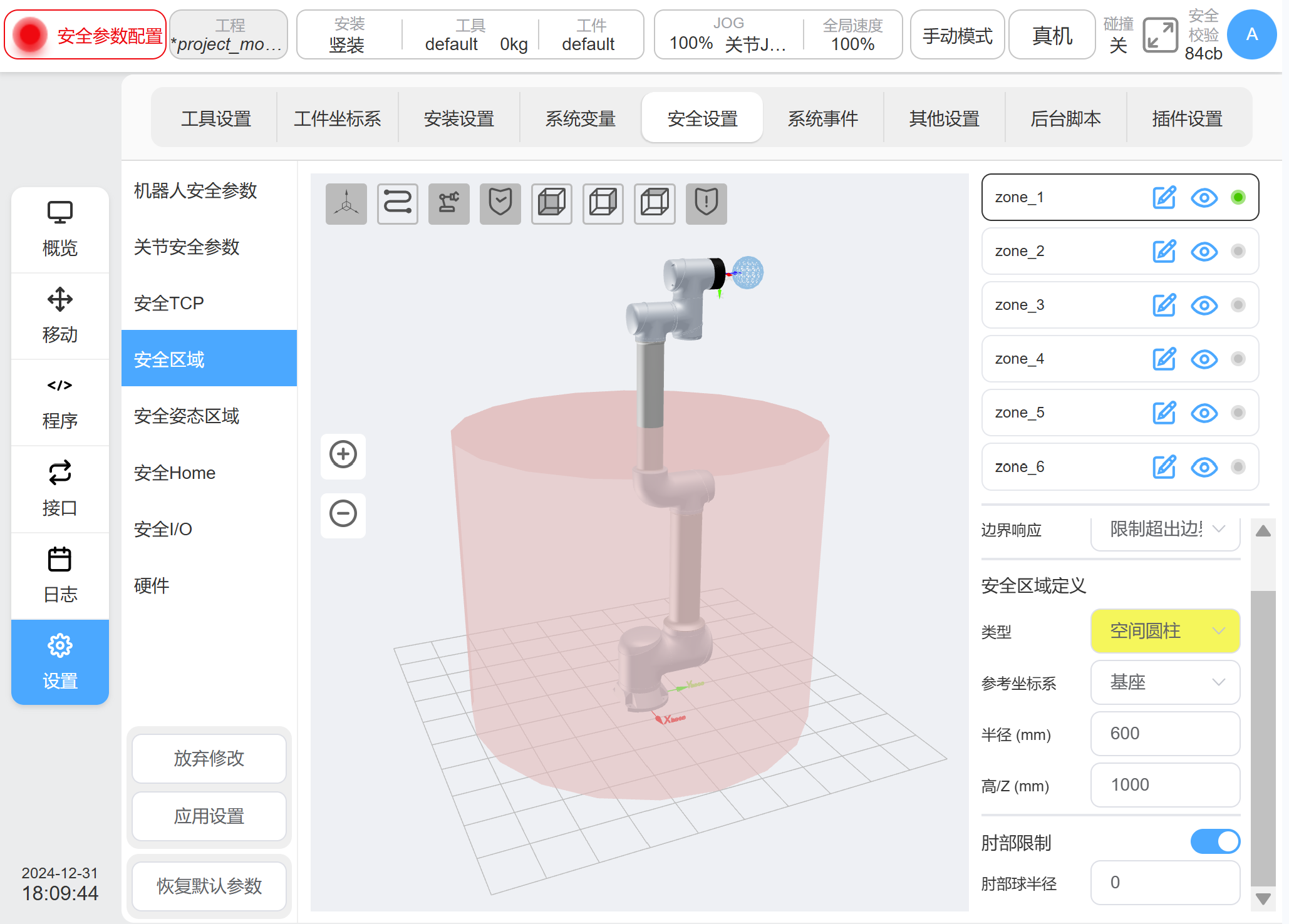
Figure 4‑8 Safety Area Maps in Spatial Cylinder#
Safety TCP Orientation#
Once the safety TCP orientation is set, the posture area which refers
to forming a conical Angle around a direction vector in the base
coordinate system of the robot will be activated. The posture
restriction only restricts the Z-axis of the robot TCP to the posture
region. Users can set up to three posture areas at most. A single
posture area can be shown or hidden by clicking the icon
 beside to the name on the right of the posture area, which
is default to display. The icon
beside to the name on the right of the posture area, which
is default to display. The icon  after the name can be
clicked to modify the pose area name.
after the name can be
clicked to modify the pose area name.  will be displayed if
the posture area is enabled, otherwise
will be displayed if
the posture area is enabled, otherwise  will be displayed as
disabled.
will be displayed as
disabled.
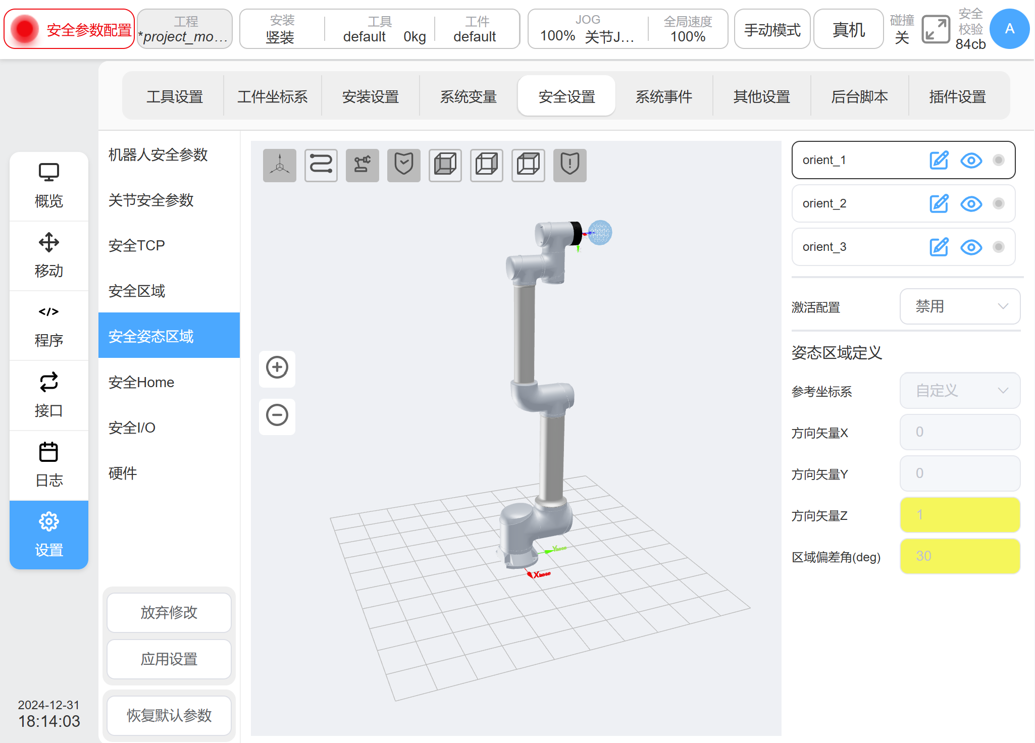
Figure 4‑9 Safety TCP orientation activate#
The safety posture area can be activated in five modes: disabled, always valid, automatic mode valid, safety group configuration 1, and safety group configuration 2. The safety TCP orientation is different from the safety zone in that only the Z axis direction of TCP is restricted, and there is only one response protective stop mode triggered after the area is exceeded.
There are three ways to define a reference coordinate system for the safety posture area: custom, capturing the current TCP pose, and defining it through a predefined work-piece coordinate system. When custom is selected, manually modify the value of the direction vector X, Y, Z, which describes the value in the robot base coordinate system; When the current TCP posture is selected, the z-axis direction of the current TCP is taken as the reference direction of the posture area, and the direction is converted to the robot base coordinate system to describe the vector direction X, vector direction Y, vector direction Z. If the value is manually modified, it will become a custom mode. When defined by the work-piece coordinate system, the Z-axis direction of the work-piece coordinate system is taken as the reference direction of the posture area, and converted to the robot base coordinate system, the value will be changed into a custom mode after manual modification.
If the orientation of the work-piece coordinate system has been
changed externally, a reminder icon  is displayed at the
reference coordinate system. The area deviation angle ranges from 5
to 180 degrees. For example:
is displayed at the
reference coordinate system. The area deviation angle ranges from 5
to 180 degrees. For example:
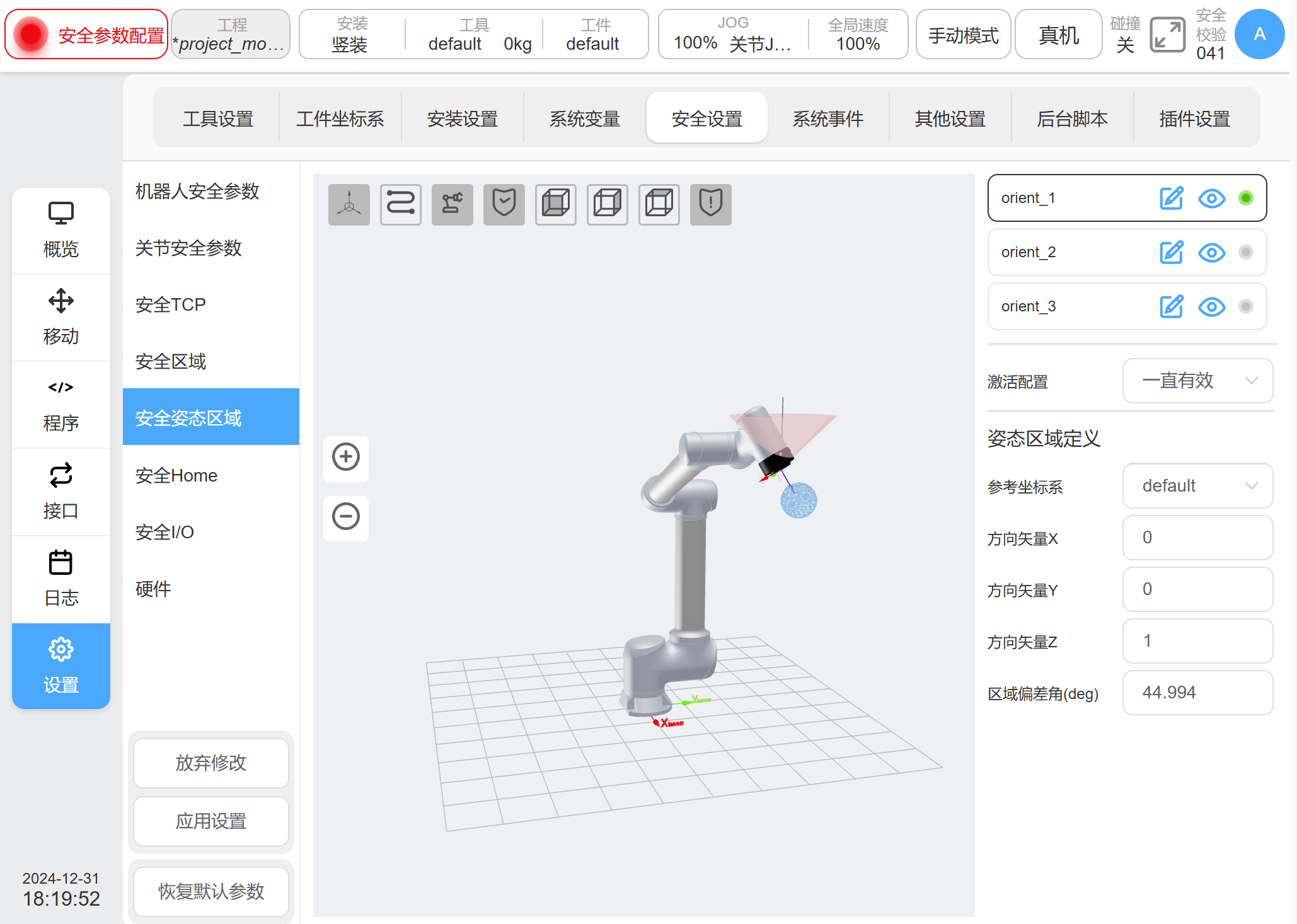
Figure 4‑10 Safety TCP orientation parameters setting#
Safe Home#
For Safe Home Settings, Safe Home Monitor will synchronize the Home
location settings in the ‘Other Settings’ screen. If the location in
the Safe Home settings does not match the Home location in Other
Settings, a reminder icon  is displayed at the Synchronize
Home Settings screen. If the settings are not synchronized, the home
position of the system is based on the safety settings. The home
point operation in the mobile interface, and the output of home
signal from other ports of the robot (e.g., port 2001) are based on
the settings of the safety controller. The home point in the ‘Other
Settings’ screen is only a record, not a basis for judging the home
point. The monitoring threshold of Home point can be set, ranging
from 1 to 5°.
is displayed at the Synchronize
Home Settings screen. If the settings are not synchronized, the home
position of the system is based on the safety settings. The home
point operation in the mobile interface, and the output of home
signal from other ports of the robot (e.g., port 2001) are based on
the settings of the safety controller. The home point in the ‘Other
Settings’ screen is only a record, not a basis for judging the home
point. The monitoring threshold of Home point can be set, ranging
from 1 to 5°.
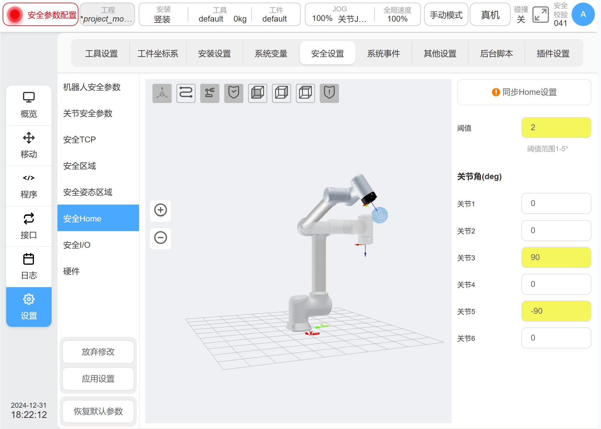
Figure 4‑11 Safety Home setting#
When the synchronized Home position is selected, the joint angle of Home position is displayed. And the 3D model display area robot model is refreshed to the corresponding position.
Safety I/O#
Two configurable safety input ports and two configurable safety output ports are included on the Safety IO module.
Safe input functions are included:
Protective stop reset input: When a guard stop occurs, this port is triggered and the robot returns to its normal state
Auto Mode protective stop input: When configured, the robot performs a guard stop when this port is triggered while the robot is in auto mode.
Auto-mode protective stop reset input: When an auto-mode guard stop occurs, trigger this port and the robot returns to normal state
Reduce Mode Input: When configured, triggering this port will transition the robot to reduce mode. The robot will decelerate so that the parameter limits match the safety parameter limits in reduced mode.
Safe Combination Configuration 1 / 2: When the Safe Combination Configuration 1 or Safe Combination Configuration 2 port is triggered, all safety features configured as Safe Combination Configuration 1 or Safe Combination Configuration 2, including Safe TCPing, Safe Zones, and Safe Gesture Zones, will be activated and started to be monitored;
Safety output features are included:
Protective stop output: This port is triggered when the robot is in the guard stop state.
Auto mode guard stop output: triggered when the robot is in auto mode guard stop
Reduce mode output: triggered when the robot is in reduce mode.
HOME position: Triggered when the robot is near the safe HOME position;
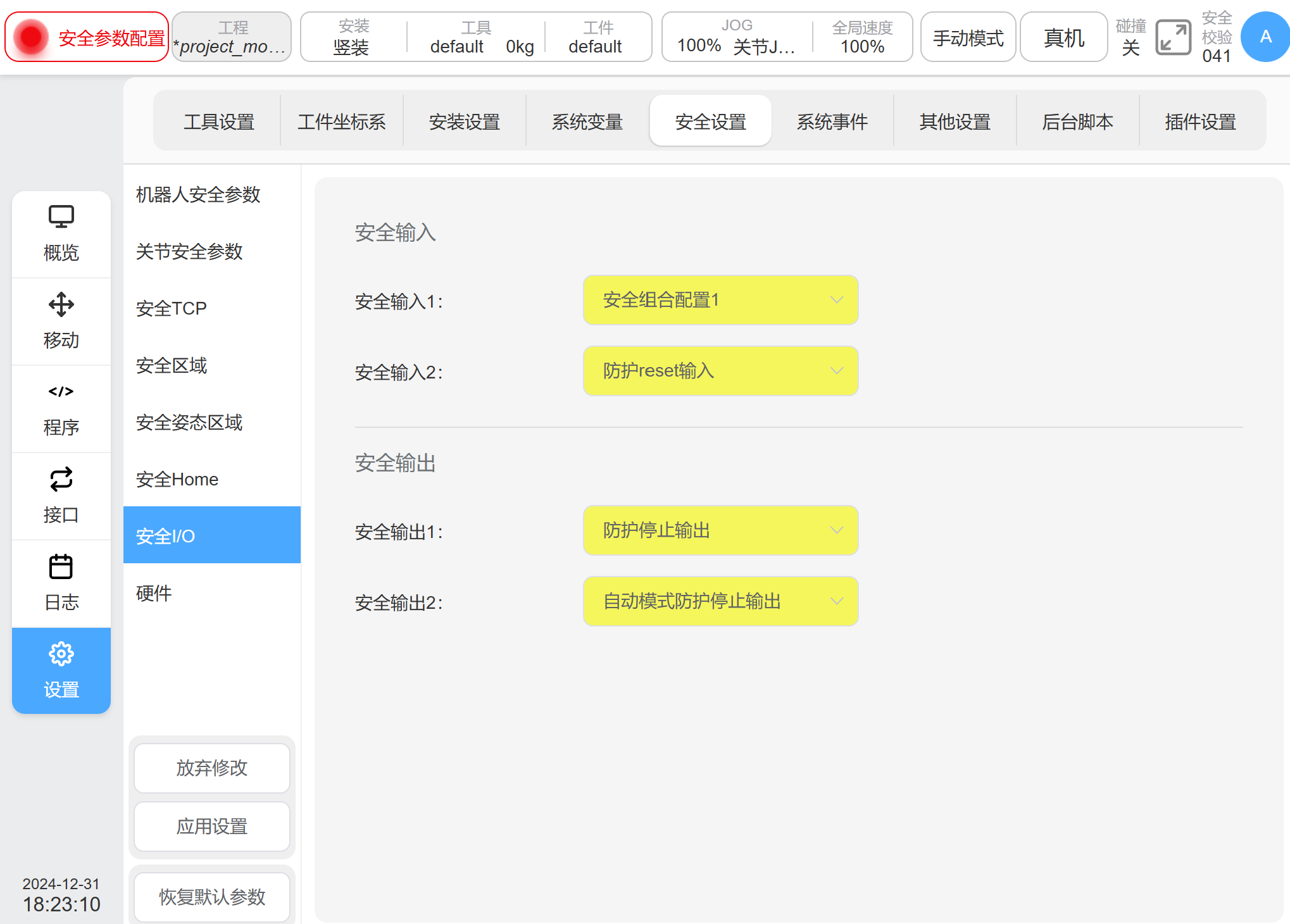
Figure 4‑12 Safety I/O setting#
Three-position Enabler#
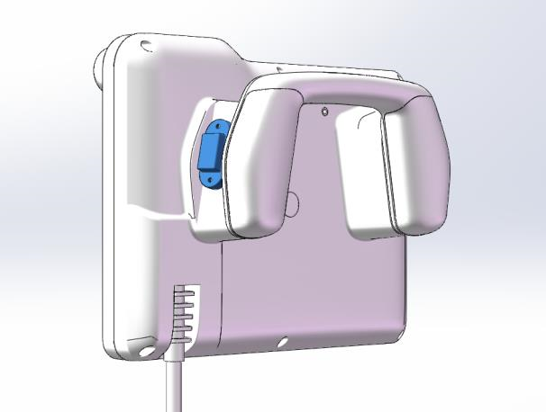
Figure 4‑13 Three-position Enabler#
In the position of the demonstrator handle, it is a three-position enabling device shown in Figure 4‑13. When the robotic arm is in manual mode, this three positions enable needs to be pressed to the center gear. If this button is not pressed, or if it is pressed fully, it will trigger Safety Stop SS2 and upon completion enter the SOS safety function to monitor abnormal arm movement.
If the Teach-pendant shielding port is using, the three-position enable function will bypass temporary. Refer to <GCR series Cobot User Manual(Control Cabinet)>
Warning
The teach-pendant (TP) shielding port is forbidden for the application of single TP and single control cabinet.
Forbidden operate robot manually while using TP shielding port. Because the three-position enable function is bypass.