


Collision Detect#
Collision Level Setting#
Collision Level |
Collision Coefficient |
Reference equivalent collision force NOTE |
|
|---|---|---|---|
Transient |
quasi-static |
||
1 |
50% |
390N |
195N |
2 |
40% |
360N |
180N |
3 |
30% |
330N |
165N |
4 |
20% |
300N |
150N |
5 |
10% |
270N |
135N |
NOTE: The reference equivalent collision force is the designed max collision force by GCR30-1100 with 250mm/s TCP speed and max payload in the dexterous workspace.
The robot provides a total of 5 levels of collision sensitivity, with higher levels providing higher sensitivity. The corresponding designed transient and quasi-static forces within the worst case (the largest robot model, the heaviest payload, the fast velocity) are shown in the table above. The factory default collision level is 4. In special application scenarios where the load cannot be measured accurately, or where the load varies greatly during operation, the collision level can be lowered after an on-site safety assessment in order to ensure that the robot can move properly.
Collision Response#
The robot provides two post-collision response actions. The default is to retreat 500ms and enter STOP 2 state. The action retreat means the robot changes to torque control mode, then the collision force will lead the robot retreat until the collision force becomes 0N. In some special application scenarios, the retreat strategy may cause a greater safety risk, in which case, it is recommended to set the collision responsive mode to “safety emergency stop”.
Since STO is an immediate disconnection of the robotic arm, due to inertia, this response action will cause the quasi-static force to no longer follow the standard requirements.
Schematic of Collaborative Forces#
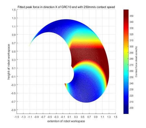
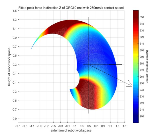
Below we provide the theoretical collision force thermograms for five robots, which were performed under the test conditions of each robotic arm, maximum load, end velocity of 250 mm/s, collision level 4, and collision response action is retreat 500ms then switch into STOP 2.
The contact point of robot body is shown as the table below:
End Effector |
Robot wrist |
|---|---|
|
|
Robot lower arm |
Robot elbow |
|
|


GCR5-910 and GCR7-910#


GCR10-1300 and GCR12-1300#


GCR20-1400#


GCR16-960#


GCR30-1100#


Schematic Reading Method#
Confirm the robot arm used.
Confirm the collision area.
Confirm the direction of collision.
4. Read the right side force information according to the color displayed at the collision location.
5. If the collision event is triggered in the red zone in thermograms, it means the collision force will exceed 300N, the system integrator should verify/test this collision force.
For example, we need to know the collision force of the end of GCR10-1300 robotic arm, in the form of Z-direction collision, when the collision occurs at the position of 0.5 meters’ horizontal distance from the base of the robotic arm and 0.3 meters’ height. By checking the figure, it can be seen that in the end load is 10KG, the end speed is 250mm/s, the collision level is 4, and the collision response is 500ms back to STOP 2, the collision force at this point is about 240N.
Collision Force Estimation#
In practice, a quick estimation of the collaborative forces is required to set parameters that are more in line with the field conditions. According to Section 3.17.1, it is known that there is about 30N of collision force variability between neighboring collision sensitivities, in addition to which end loads and end velocities have a large impact on the final collision effect.
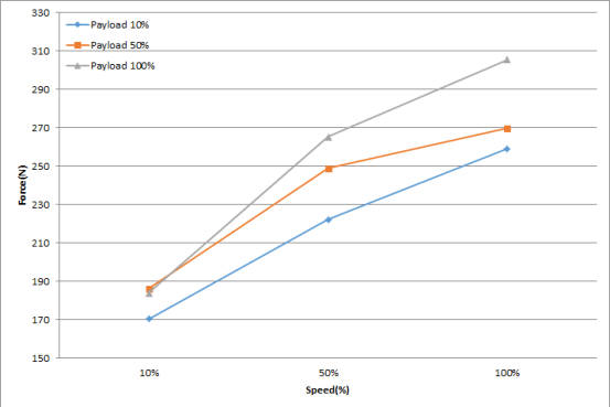
Figure 3‑1 collision force effect of speed & payload#
The user can estimate the collision force based on the theoretical values obtained from the heat map lookup table after it has been completed, and again based on the trend graph of the effect of load and speed on the collision force shown in the table above.
For example, it is necessary to know the collision force of the end of the GCR10 robotic arm when a collision occurs in the Z-direction collision with the condition of setting the collision level to 3 at the position of 0.5 meters horizontal distance from the base of the robotic arm and 0.3 meters height with an end load of 5 KG and an end speed of 125 mm/s.
The reference collision force for this condition can be 240N according to the description in section 3.17.9.
According to chapter 3.17.1, it can be seen that the reference force increases by approximately 30N when the collision level is 3.
Based on the trend graphs in this section, it can be seen that when the load is reduced by half and the speed is reduced by half, the reference force is approximately 250/300 = 83% of the reference force.
Estimate the collision force for this condition as (240+30) x (250/300) = 225N