DC00-J9 controller#
The DC00 controller is built into the DC30D/15S, providing the algorithm implementation, motion control, human-computer interaction and other functions of the robot system, and the peripheral port provides external communication, IO and other functions. The DC00 controller is available as a separate control unit (see sections 5, 6 for details).
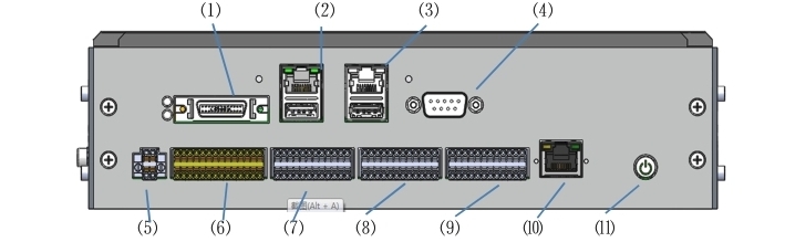
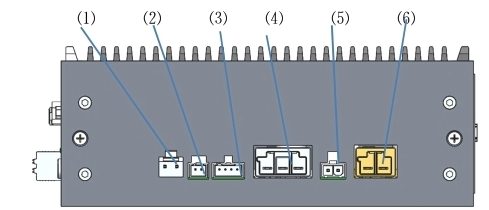
The appearance style of DC00 controller is shown in Figure 5, and the port diagram and port description are shown in Figure 6:
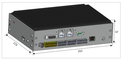
Figure 6 Appearance of the DC00 controller
No |
Port |
No |
Port |
|---|---|---|---|
1 |
VGA&COM3/4 |
2 |
LAN1+USB3.0 |
3 |
LAN2+USB2.0 |
4 |
COM1 |
5 |
IO POWER(IO power supply) |
6 |
SIO(safety IO) |
7 |
DIO(Digital IO) |
8 |
CIO(Configurable IO) |
9 |
EIO(Function Expansion IO) |
10 |
EtherCAT2 |
11 |
ON/OFF(Power On and off) |
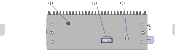
No |
Port |
No |
Port |
|---|---|---|---|
1 |
ANT(WIFI Antenna) |
2 |
TP(Teach-pendant IO) |
3 |
Grounding |
No |
Port |
No |
Port |
|---|---|---|---|
1 |
24V_INPUT |
2 |
FAN |
3 |
EtherCAT1 |
4 |
48V_OUTPUT |
5 |
TR(Resistance to braking) |
6 |
48V_INPUT |
Figure 7 port diagram of DC00 controller
ANT PORT#
The ANT (WIFI antenna) port is a male internal needle, used to install the antenna extension cable, or optionally a gain antenna with a female internal hole;
TP PORT#
TP (teach pendant IO) port is used to interact with teach pendant terminal box. teach pendant emergency stop, enable, mode selection, signal with light switch button. The port definition is shown in Table 9:
Table 9 TP port definitions

No |
Signal Definition |
No |
Signal Definition |
|---|---|---|---|
1 |
EN1+(Three-position enable input 1+) |
2 |
EN1-(Three-position enable input 1-) |
3 |
EN2+(Three-position enable input 2+) |
4 |
EN2-(Three-position enable input 2-) |
5 |
SEL1+(Mode switching input 1+) |
6 |
SEL1-(Mode switching input 1-) |
7 |
SEL2+(Mode switching input 2+) |
8 |
SEL2-(Mode switching input 2-) |
9 |
EMG1+(TP emergency stop input 1+) |
10 |
EMG1-(TP emergency stop input 1-) |
11 |
EMG2+(TP emergency stop input 2+) |
12 |
EMG2-(TP emergency stop input 2-) |
13 |
PUSH+(Button input with light +) |
14 |
PUSH-(Button input with light -) |
15 |
24V |
16 |
0V |
Note: This port must be connected when in use; The wiring harness of the emergency stop button box needs to be connected in WIFI mode. In the teach pendant mode, it is necessary to connect the teach pendant harness; Otherwise, an emergency stop will be triggered.
Ground connection PORT#
This port is connected to the PE cable, which is used to eliminate static electricity of the shell and protect the equipment and personal safety.
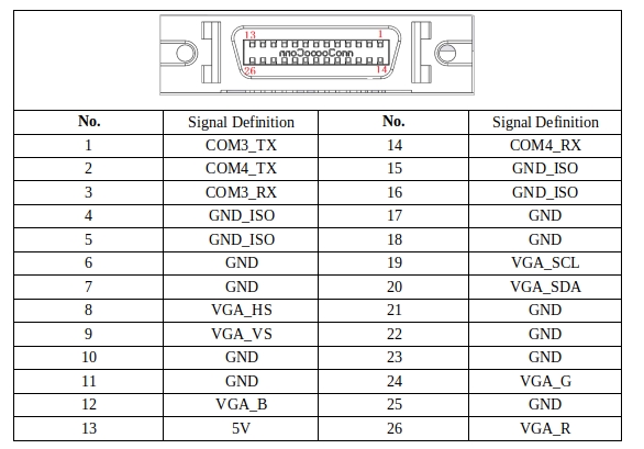
VGA&COM3、4 PORT#
VGA&COM3/4 port is used for the display of the display screen and the signal of the operation of teach pendant. The port definition is shown in Table 10:
Table 10 shows the VGA+232 port definition of teach pendant
LAN1+USB3.0 PORT#
LAN1 port, 1000M, support PROFINET/MODBUS TCP/ TCP IP communication, used to communicate with other controllers and robots to achieve robot control; Standard network cable port, no longer display port definition;
USB3.0 port is used to connect devices such as mouse and keyboard, and facilitate technical personnel to connect U disk devices to copy software. Standard USB3.0 port, no longer display port definition;
LAN2+USB2.0 PORT#
LAN2 port, 1000M, support MODBUS TCP /TCP IP communication, used to communicate with other controllers and robots to achieve robot control; Standard network cable port, no longer display port definition;
USB2.0 port is used to connect devices such as mouse and keyboard, and to facilitate technical personnel to connect U disk devices for software copy. Standard USB2.0 port, no longer display port definition;
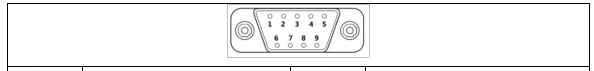
COM1 PORT#
The COM1 port is an RS232 port.
This port is a DB9 male pin connector. The port definition is shown in Table 11:
Table 11 COM1 port definition
No |
Signal Definition |
No |
Signal Definition |
|---|---|---|---|
1 |
NC |
2 |
COM1_RX |
3 |
COM1_TX |
4 |
NC |
5 |
GND_ISO |
6 |
NC |
7 |
NC |
8 |
NC |
9 |
NC |
IO POWER PORT#
The IO POWER port is used to power digital I/O and analog I/O. The port definition is shown in Table 12:
It is recommended to use 8MM tubular terminals of 22AWG(0.2-0.3²) or less for the wiring harness
Table 12 IO POWER port definition
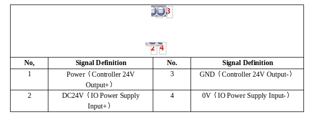
Note: Depending on the I/O load power, you can use the internal power supply and external power supply
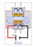
For internal power supply, short-connect pin 1 to pin 2, and pin 3 to pin 4; At this time, 24V DC up to 2A will be provided internally (as shown)
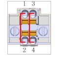
For external power supply, remove the short cable and connect pin 2 to DC24V and pin 4 to DC0V. 24V DC of up to 8A when powered externally (as shown)
SIO PORT#
The SIO (Safety IO) port is an external SCram and safety input and output port provided by the controller, including one user SCram signal input, one system scram feedback output (active signal), one protective stop input, two configurable safety inputs, and two configurable safety outputs (active signal). Protective stop input and configurable safety input as dry contact port; In addition, when the configurable safety output and system scram feedback output are used, the relay needs to be connected for switching. For instructions on how to set up this port through software, see the Duco core user manual. The port definition is shown in Table 13:
It is recommended to use 8MM tubular terminals of 22AWG(0.2-0.3²) or less for the wiring harness
Table 13 SIO port definitions
No |
Signal Definition |
No |
Signal Definition |
|---|---|---|---|
1 |
EI1+ (User emergency stop signal input 1+) |
2 |
EI1- (User emergency stop signal input 1-) |
3 |
EI2+ (User emergency stop signal input 2+) |
4 |
EI2- (User emergency stop signal input 2-) |
5 |
PSI1+ (Protective stop input 1+) |
6 |
PSI1- (Protective stop input 1-) |
7 |
PSI2+ (Protective stop input 2+) |
8 |
PSI2- (Protective stop input 2-) |
9 |
CSI1_1+ [Configurable safety input 1(1+)] |
10 |
CSI1_1- [Configurable safety input 1(1-)] |
11 |
CSI1_2+ [Configurable safety input 1(2+)] |
12 |
CSI1_2- [Configurable safety input 1(2-)] |
13 |
CSI2_1+ [Configurable safety input 2(1+)] |
14 |
CSI2_1- [Configurable safety input 2(1-)] |
15 |
CSI2_2+ [Configurable safety input 2(2+)] |
16 |
CSI2_2- [Configurable safety input 2(2-)] |
17 |
EO1+(System emergency stop feedback output 1+) |
18 |
EO1-(System emergency stop feedback output 1-) |
19 |
output 2+) |
20 |
EO2-(System emergency stop feedback output 2-) |
21 |
CSO1_1+[Configurable safety output 1(1+)] |
22 |
CSO1_1-[Configurable safety output 1(1-)] |
23 |
CSO1_2+[Configurable safety output 1(2+)] |
24 |
CSO1_2-[Configurable safety output 1(2-)] |
25 |
CSO2_1+[Configurable safety output 2(1+)] |
26 |
CSO2_1-[Configurable safety output 2(1-)] |
27 |
CSO2_2+[Configurable safety output 2(2+)] |
28 |
CSO2_2-[Configurable safety output 2(2-)] |
The electrical parameters of the safety IO port are shown in Table 14:
Table 14 Safety IO port parameters (PNP type)
safety DI |
||||
Terminal |
Parameter |
|||
EIx |
Dry contact input |
|||
PSIx |
Dry contact input |
|||
CSIx |
Dry contact input |
|||
safety DO |
||||
Terminal |
Parameter |
Minimum |
Typical Value |
Maximum |
EOx/CSOx |
Current |
0A |
— |
0.5A |
Voltage |
23.52V |
24V |
25.2V |
|
Signal type |
PNP |
|||
The safe DI timing diagram is shown in Figure 8:
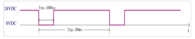
Figure 8 Security input timing diagram
The diagnostic pulse at the safety DI input is shown in Figure 7. The MCU checks whether the hardware circuit is faulty by sending a diagnostic pulse with a period of 20ms and a negative pulse width of 500 (±100) μs.
The safety DO timing is shown in Figure 9:
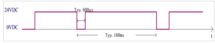
Figure 9 Safety output timing diagram
The output diagnostic pulse of the safety DO output is shown in Figure 8. The MCU sends an output control signal with a diagnostic pulse signal with a diagnostic pulse period of 160ms and a negative pulse width of 600 (±100) μs.
SIO port wiring diagram#
a Default safety configuration
Figure 10 shows the wiring diagram of the default configuration of the safety interface, which allows robot operation without any additional safety devices.
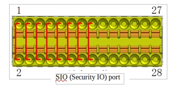
Figure 10 Default safety configuration wiring diagram
d Connect the external security input signal
Figure 11 shows the connection diagram between the safety input port and the external safety input signal. Note that the external safety input signal is a dry contact signal, and the emergency stop button is used as an example.
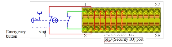
Figure 11 External safety signal input wiring diagram
e Connect the protective stop signal
Figure 12 shows the wiring diagram of the protective stop input signal. Note that the external protective stop input signal is a dry contact signal.
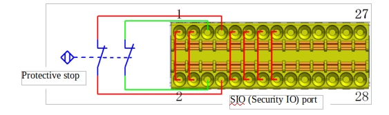
Figure 12 Protective stop signal input wiring diagram
f Connection can be configured with safety input signals
The configurable safety input signal wiring diagram is similar to the protective stop input signal wiring.
g Share emergency stops with other machines
When the robot is used with other machines, it is often necessary to set up a public emergency stop circuit. By setting up a public line, the operator doesn’t have to think about which emergency stop button to use.
Since both machines need to wait for each other to jump out of the emergency stop condition, the standard robot emergency stop input cannot be used for sharing, and to share the emergency stop function with other machines, it must be configured through the safety input and safety output of the controller safety IO.
In addition, the safety output is an active signal, which needs to be connected to the relay before use, as shown in Figure 13:
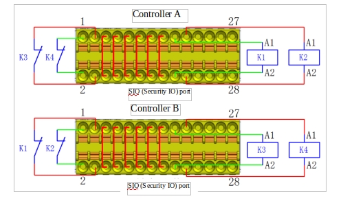
FIG. 13 Schematic diagram of emergency stop of two robot controllers
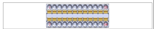
DIO PORT#
The DIO (digital IO) port provided by the controller includes 8-way digital input (DI) port and 8-way digital output (DO) port. The port definition is shown in Table 15:
Here, it is recommended to use 22AWG(0.2-0.3²) or less, length of 8MM tubular terminals.
Table 15 DIO port definitions
No |
Signal Definition |
No |
Signal Definition |
|---|---|---|---|
1 |
24V |
2 |
0V |
3 |
24V |
4 |
0V |
5 |
DI1(Normal DI input 1) |
6 |
DO1(Normal DO output 1) |
7 |
DI2(Normal DI input 2) |
8 |
DO2(Normal DO output 2) |
9 |
DI3(Normal DI input 3) |
10 |
DO3(Normal DO output 3) |
11 |
DI4(Normal DI input 4) |
12 |
DO4(Normal DO output 4) |
13 |
DI5(Normal DI input 5) |
14 |
DO5(Normal DO output 5) |
15 |
DI6(Normal DI input 6) |
16 |
DO6(Normal DO output 6) |
17 |
DI7(Normal DI input 7) |
18 |
DO7(Normal DO output 7) |
19 |
DI8(Normal DI input 8) |
20 |
DO8(Normal DO output 8) |
21 |
24V |
22 |
0V |
23 |
24V |
24 |
0V |
Digital Input (DI)#
The controller provides a digital input (DI) interface whose input voltage ranges from -3 to 30VDC (0 to 15mA). Table 16 lists the electrical parameters of the port.
Table 16 DI interface parameters (PNP type)
Terminal |
Parameter |
Minimum |
Typical Value |
Maximum |
Digital Input |
||||
DIX-24V |
Voltage |
-3V |
—— |
30V |
DIX-24V |
ON area |
11V |
—— |
30V |
DIX-24V |
OFF area |
-3V |
—— |
5V |
DIX-24V |
TON/TOFF delay |
TON:50ms TOFF: 50ms |
||
DIX-24V |
Fuction |
PNP type |
||
a Dry contact signal input
Figure 14 shows the cable connection between the dry contact signal (button) and the DI port.
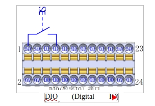
Figure 14 Dry contact signal input wiring diagram
h PNP signal input
Figure 15 shows the wiring mode of PNP signal (PLC DO port output, PNP type) input and DI port.
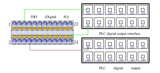
Figure 15 PNP signal input wiring diagram
Digital Output (DO)#
The controller provides A digital output (DO) interface. The output voltage ranges from 23.52-25.2VDC, and the maximum current is 0.5A. The switching time is as follows: Table 17 lists the electrical parameters of the port:
Table 17 DO interface parameters (PNP type)
Terminal |
Parameter |
Minimum |
Typical Value |
Maximum |
Digital Output |
||||
DOX-0V |
Current |
0A |
—— |
0.5A |
DOX-0V |
Voltage |
23.52V |
—— |
25.2V |
DOX-0V |
TON/TOFF delay |
TON:50ms TOFF: 50ms |
||
DOX-0V |
Function |
PNP type |
||
a DO output connection load
Figure 16 shows the wiring diagram of the DO output directly connected to the load (relay), with a maximum output current of 0.5A.
Figure 16 DO output and load reference wiring diagram
i DO output and other PNP input equipment wiring diagram
Figure 17 shows the connection diagram between the DO port output and other PNP type DI input devices (PLCS) :
Figure 17 Connection diagram with other PNP type DI input devices
CIO PORT#
The CIO (configurable digital IO) interface provided by the controller includes eight configurable digital input (DI) ports and eight configurable digital output (DO) ports. This port can be configured as user DIO or function DIO through software operation, and the default setting is user DIO. The port definition is shown in Table 18:
Here, it is recommended to use 22AWG(0.2-0.3²) or less, length of 8MM tubular terminals.
Table 18 Configurable digital I/O port definitions
编号 |
信号定义 |
编号 |
信号定义 |
|---|---|---|---|
1 |
24V |
2 |
0V |
3 |
24V |
4 |
0V |
5 |
CDI1 (Configurable DI input 1) |
6 |
CDO1 (Configurable DO output 1) |
7 |
CDI2 (Configurable DI input 2) |
8 |
CDO2 (Configurable DO output 2) |
9 |
CDI3 (Configurable DI input 3) |
10 |
CDO3 (Configurable DO output 3) |
11 |
CDI4 (Configurable DI input 4) |
12 |
CDO4 (Configurable DO output 4) |
13 |
CDI5 (Configurable DI input 5) |
14 |
CDO5 (Configurable DO output 5) |
15 |
CDI6 (Configurable DI input 6) |
16 |
CDO6 (Configurable DO output 6) |
17 |
CDI7 (Configurable DI input 7) |
18 |
CDO7 (Configurable DO output 7) |
19 |
CDI8 (Configurable DI input 8) |
20 |
CDO8 (Configurable DO output 8) |
21 |
24V |
22 |
0V |
23 |
24V |
24 |
0V |
Note: Please refer to the Duco core user manual for instructions on how to configure this port to user DIO or function DIO through software Settings
Configurable Digital Input (CDI)#
The controller provides a configurable digital input (CDI) interface. The input voltage ranges from -3-30VDC (0 to 15mA). For the interface parameter table, time sequence diagram, and connection mode, see section 4.10.1 Digital Input (DI).
Configurable Digital Output (CDO)#
The controller provides A configurable digital output (CD0) interface with an output voltage range of 23.52-25.2VDC and a maximum current of 0.5A. Interface parameter table, time sequence diagram, connection mode, please refer to 4.10.2 Digital Output (D0) chapter description;
EIO PORT#
The EIO (Function Extension IO) port of the DC00 controller is two configurable analog input ports, two configurable analog output ports, one external CAN communication port, one external RS485 communication port, INC encoder differential signal port, and one remote updown port provided by the controller. The port definition is shown in Table 19:
Here, it is recommended to use 22AWG(0.2-0.3²) or less, length of 8MM tubular terminals.
Note: The 24V power supply of the INC encoder may cause damage to the slave port board in case of short circuit. Avoid short circuit during use.
Table 19 Function Extension 1 port definition
No |
Signal Definition |
No |
Signal Definition |
|---|---|---|---|
1 |
AI1(Configurable analog input 1) |
2 |
AG(Analog Grounding) |
3 |
AI2(Configurable analog input 2) |
4 |
AG(Analog Grounding) |
5 |
AO1(Configurable analog output 1) |
6 |
AG(Analog Grounding) |
7 |
AO2(Configurable analog output 2) |
8 |
AG(Analog Grounding) |
9 |
24V |
10 |
RC1(Remote Switch ON+) |
11 |
0V |
12 |
PowerON(Remote Switch ON-) |
13 |
A+(INC signal A phase +) |
14 |
RC2(Remote Switch OFF+) |
15 |
A-(INC signal A phase -) |
16 |
Power0FF(Remote Switch OFF-) |
17 |
B+(INC signal B phase +) |
18 |
CAN_L |
19 |
B-(INC signal B phase -) |
20 |
CAN_H |
21 |
Z+(INC signal C phase +) |
22 |
485_B |
23 |
Z-(INC signal C phase -) |
24 |
485_A |
Configurable analog interface#
a Configurable analog input (0~10V/4~20mA,±1%)
Configurable analog input interface can be configured by software into voltage analog input or current analog input two different working modes (factory default 0-10V voltage input);
Note: Please refer to the Duco core User Manual for instructions on how to configure this interface as a voltage or current analog input via software
j Configurable analog output (4-20mA/0~10V,±1%)
Configurable analog output interface can be configured by software into voltage analog output or current analog output two different working modes (factory default 0V voltage output);
Note: Please refer to the Duco core User Manual for instructions on how to configure this interface as a voltage or current analog input via software
k analog signal isolation specification
Electrical isolation between analog signals, electrical specifications refer to Table 20:
Table 20 Electrical specifications for analog quantities
Terminal |
Parameter |
Minimum |
ypical Value |
Maximum |
Analog input in current mode |
||||
AI_CX-AGND |
Current |
4mA±1% |
—— |
20mA±1% |
Resistance |
— |
160Ω |
— |
|
Resolution |
— |
12bit |
— |
|
Analog input in voltage mode |
||||
AI_VX-AGND |
Current |
0V±1% |
—— |
10V±1% |
Resistance |
— |
15KΩ |
— |
|
Resolutio |
— |
12bit |
— |
|
l Analog wiring diagram
Figure 18 shows the schematic diagram of analog interface wiring:
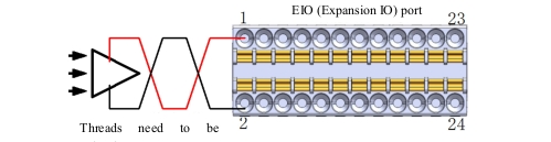
Figure 18 Schematic diagram of analog input wiring
Communication interface (CAN,RS485,INC signal)#
External communication interfaces are isolated from each other, and the communication parameter specifications are shown in Table 21:
Table 21 Communication parameter specifications
Terminal |
Parameter |
Data |
CAN communication |
Baud rate |
10k, 20k,50k ,100k ,125k,250k, 500k,1000k bps |
RS485 communication |
Baud rate |
4800, 9600,19200 ,38400 ,115200 bps |
Line impedance |
120Ω |
|
INC encoder communication A+,A-;B+,B-;Z+,Z- |
Supply voltage |
24VDC |
Allowable frequency |
<200KHz |
|
Input signal |
Square wave signal (compatible with single terminal/differential) |
Figure 19 shows the schematic diagram of INC interface differential encoder connection:
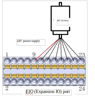
Figure 19 Schematic diagram of differential INC encoder connection
Figure 20 shows the schematic diagram of INC interface single-ended encoder connection:
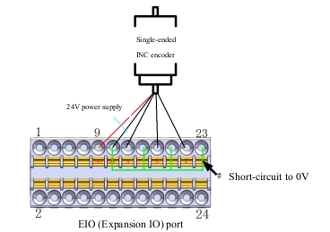
FIG. 20 Schematic diagram of single-ended INC encoder connection
Remote switching interface#
With the remote switch, the system can be turned on or off without the use of teach pendant or the power on button on the controller panel.
The PowerON input is the same as the power-on button. You must use PowerOFF input for remote shutdown. This signal allows the controller to save the opened file and shut it down normally (similar to a system soft shutdown).
The remote switch interface is defined as shown in Table 22:
Table 22 Remote switch interface definition
Connector Numbe |
Signal Definition |
Input Signal Type |
10 |
RC1 |
Dry contact |
12 |
PowerON |
|
14 |
RC2 |
Dry contact |
16 |
PowerOFF |
Electrical specifications are shown in Table 23 as follows:
Table 23 Electrical specifications for remote switching interfaces
Terminal |
Parameter |
Minimum |
Maximum |
PowerON-RC1 |
Voltage |
0VDC |
25.2VDC |
PowerOFF -RC2 |
Voltage |
0VDC |
25.2VDC |
PowerON activation time |
>1S |
||
PowerOFF Turn-off time |
>3S |
||
The connection method of the remote switch is as follows:
a Remote PowerON port (dry contact input)
Figure 21 shows how the remote PowerON button is wired, where the button uses a self-reset button.
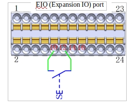
Figure 21 Remote power-on cable diagram
m Remote PowerOFF port (dry contact input)
Figure 22 shows how the remote PowerOFF button is wired, where the button uses a self-reset button.
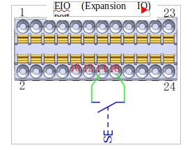
Figure 22 Schematic diagram of remote power-off cable
EtherCAT2 PORT#
EtherCAT2 port, supporting EtherCAT communication; Reserve for use; Standard network cable port, no longer display port definition;
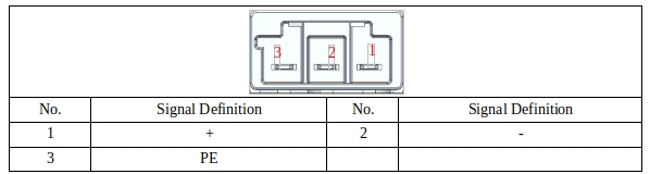
24V_INPUT PORT#
The 24V_INPUT PORT is connected to an externally supplied power supply to power the MCU end master controller of the DC00 controller. The port definition is shown in Table 24:
Table 24 24V_INPUT port definition
FAN PORT#
The FAN port is used to drive current to the DC FAN(no frequency conversion); The output voltage of this port is DC24V, and the output current is up to 2A. It is recommended to use a DC fan with a power of 5 to 10W. The port definition is shown in Table 25:
Table 25 Definitions of fan ports
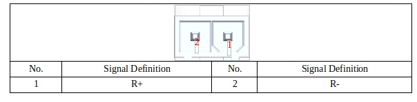
EtherCAT 1 PORT#
The EtherCAT 1 port is dedicated to communicating with the robot; The port definition is shown in Table 26:
Table 26 Ecat OUT1 port definitions
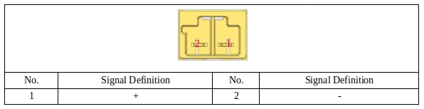
48V_OUTPUT PORT#
48V_OUTPUT port is dedicated to providing DC48V power to the robot, and its port definition is shown in Table 27:
Table 27 DC48V output port definition
TR PORT#
TR port is connected to brake resistance; When the torque of the motor and the speed of the opposite direction, it represents the energy from the load end back to the driver. This energy recharge causes the voltage value to rise. When it rises to a certain value, the energy of the recharge can only be consumed by the brake resistance. The port definition is shown in Table 28:
The standard brake resistance is 150W, 3Ω.
Table 28 Brake resistance port definition
48V_INPUT PORT#
48V_INPUT port is dedicated to provide DC48V power to the robot; The port definition is shown in Table 29:
Table 29 DC48V input port definition
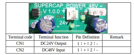
24V module PORT#
Table 32 shows the port description of the 24V module:
Table 30 port definition of 24V module.