Electrical Installation#
brief introduction#
This section mainly describes the basic matters that should be paid attention to when installing a robot system.
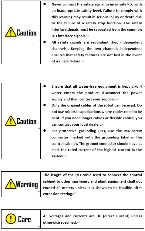
Warning and caution signs#
Always follow the following warnings and precautions when installing a robot system. Follow these warnings and precautions when performing maintenance operations.
Control cabinet installation#
The control cabinet should be placed on a flat surface. A 50mm gap should be reserved on each side of the control cabinet to ensure smooth air circulation. The support at the bottom of the control cabinet has holes reserved for installation. Install 4*M8 bolts as required. For details, see Appendix F: Dimensions of DC15S/DC30D control cabinets.
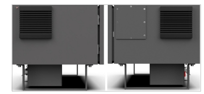
Figure 8.1 Direction diagram of fan dust cover in robot control cabinet
Note: For different types of control cabinets, install the fan dust cover in the correct direction; otherwise, the IP protection level will be affected.
Teaching application#
The optional teach pendant or PAD is used for programming, display and operation of the robot system. The application forms are listed as follows:
Application Scenario 1: Optional teach pendant (1 teach pendant and 1 control cabinet)
In this application scenario, the teach pendant is not removed or inserted during use, and the shielding port of the teach pendant cannot be used.

Application Scenario 2: Optional teach pendant (1 teach pendant with multiple control cabinets) ·
In this application scenario, when the control cabinet connected to teach pendant is connected, the shielding port of teach pendant is prohibited. For control cabinets where teach pendant is removed, teach pendant shielding port must be connected to a prefabricated 8-pin short-circuit plug and pull connector (optional).
Robot is Automatic operation In mode, the process of removing teach pendant is as follows:
1. Insert the prefabricated 8-core short-plug connector into the control cabinet teach pendant shielding interface;.
Unplug and show teach pendant plug.
Re-insert the indicator (the control cabinet is not connected to the indicator when the robot is in automatic mode)
Confirm that the gear switch of teach pendant is in A (automatic) gear;
Insert the connector of teach pendant into the port of teach pendant;
Unplug the 8-core short-circuit plug connector.
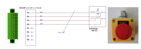
Application Scenario 3: Optional PAD
When using the PAD, the SCram function must be configured. Insert the SCram button box into the shielding port of teach pendant.. Emergency stop button box is optional, please contact the dealer to purchase. The default length of the optional emergency stop button box wiring harness is 5m. If the length is not suitable, users can make their own wiring harness according to actual needs. The wiring principle diagram is as follows: