01 Product Description#
An overview of robot system#
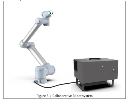
The collaborative robot system mainly consists of the following parts:
Robot body
Robot control cabinet
Connect cables
Software
Other optional accessories, accessories
Robot ontology specification#
Robot ontology overview#
The collaborative robot is composed of a base and 6 modular joints with functions such as traction, teaching and collision detection. The robot can be installed in any direction. Each joint of the robot is equipped with an encoder to detect the operating position of the joint, and a reliable braking system is equipped for stopping.
The robot body is mainly composed of the following parts:
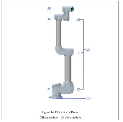
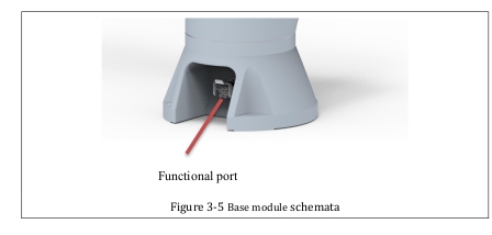
Base Module①
The base module is at the bottom of the robot, and the robot cables are connected to the control cabinet through the port board of the base module to provide power supply and data transmission for the robot.
Joint module②
Each robot is made of six joints, with a separate drive module and an aluminum alloy casting shell.
Electrical System
The electrical system consists of all the electrical components (including drivers, connectors, cables, etc.) that power and control each articulated motor.
Robot joint coordinate#
The robot joint coordinate diagram is as follows:
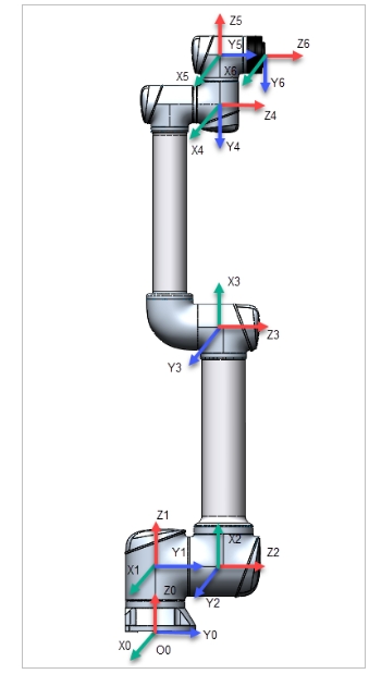
Figure 3-12 Schematic diagram of robot joint coordinates
Robot zero position and positive direction#
The robot zero position and positive direction are as follows:
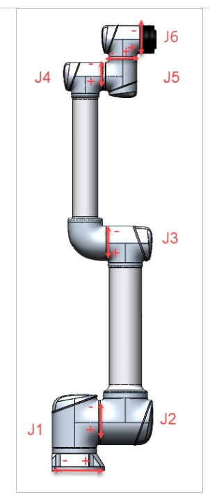
Figure 3-13 Robot zero position and robot positive direction
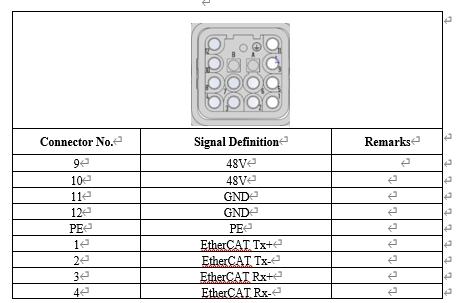
Base Enter the panel description#
The base input panel is located at the bottom of the robot and contains a communication power supply port for connecting cables between disks to provide power supply and data transmission for the robot.
The robot port is defined as follows:
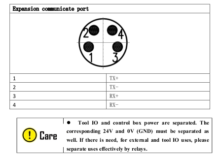
Wrist flange description#
The end of robot is a wrist flange (in accordance with GB/T 14468.1-50-4-M6 and ISO 9409-1-0-4-M6 standard), and the flange has a screw hole and a pin hole for installation, which can be used to install the end tool. The extended I/O port and communication port on the flange can be used to connect the end tool.
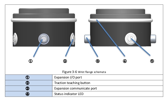
This connector provides power and control signals for grippers and sensors used on specific robot tools, as shown below:
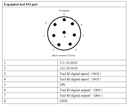
Basic electrical parameters:
2-way digital output DO drive capability (24V 0.6A)
▪ Provides tools for basic start-stop drive control
2 digital input DI
▪ Provides voltage input signals up to 24V
1 24V power supply, maximum power 28.8W
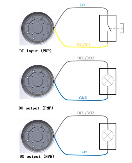
The tool I/O connection mode is as follows:
Strip definition#