04GCR7-910 Robot#
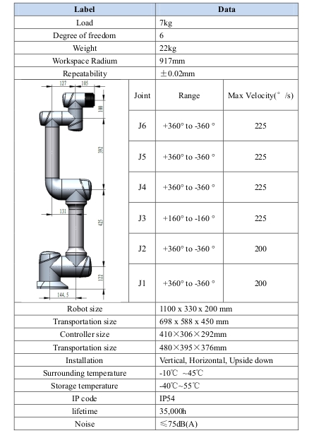
Robot technical parameter#
Basic parameter#
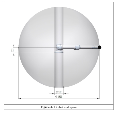
Work space#
The shape and size of the collaborative robot workspace are as follows:
load#
Load basic parameter#
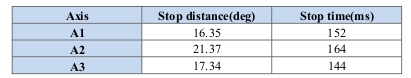
Load diagram#
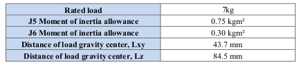
The rated load size is related to the distance between the center of gravity of load and the end shaft flange. For a certain load, the rated offset distance between the center of gravity of the load and the center of the end flange is shown in the load curve in Figure 4-17.

The load curve corresponds to the maximum load capacity. Each load must check two values (load mass and moment of inertia). It will affect the service life of the robot.
The load mass and moment of inertia obtained here are very important when planning the use of the robot. According to the corresponding operation and programming guidelines, the load mass and moment of inertia need to be input into the robot control system when the robot is put into operation.
Stop time and stop distance#
Basic description#
General information about stop parameters:
Stop distance refers to the Angle of the robot from triggering the stop signal to a complete stop.
Stop time refers to the time taken by the robot from triggering the stop signal to a complete stop.
The data shown is for base axes A1, A2, and A3. The base axis is the axis with the greatest deflection.
Shaft movements that overlap each other may result in longer stopping trips.
The travel and time of the delayed operation are in accordance with DIN EN ISO 10218-1.
Type of downtime:
Stop Category 0 » Stop0
Stop Category 1 » Stop1
According to IEC 60204-1:
The given value for stop 0 is a reference value derived from tests and simulations. They are average values and meet the requirements specified in DIN EN ISO 10218-1. The actual stopping distance and stopping time may vary depending on internal and external effects on the braking torque. Therefore, it is recommended to determine the stop travel and stop time under the actual conditions of the robot site if necessary.
Depending on the mode of operation, the use of the robot, and the number of STOP0s triggered, different brake wear conditions may occur. It is therefore recommended to check the stopping distance at least once a year.
Stop time and stop distance of axes 1 to 3 at Stop0#
The following table shows the stop distance and stop time when the trigger stop category is Stop 0. The data is for the following configurations:
Range l = 100%
Velocity multiplier POV = 100%
Mass m = maximum load
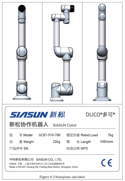
Name plate and label#
The following nameplates and labels are attached to the robots and control systems. It is not allowed to remove it or make it unrecognizable. Unrecognized nameplates and labels must be replaced.
Mechanical installation#
Base parameter#
The specific forces and moments required for mounting the base are given below, including the robot’s load and inertial forces.
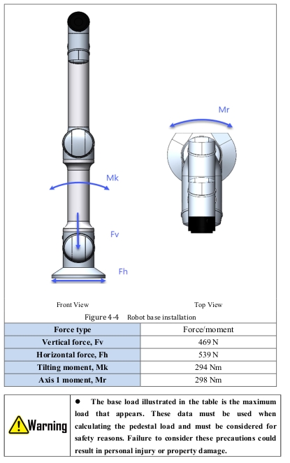
Base mounting#
The robot body uses four M8 (level 10.9 and above) bolts, two Ø6 pins, and is positioned through four 9mm holes and two pin holes in the robot base. Bolts are recommended to be tightened at 35N·m torque.
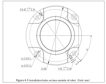
The robot must be mounted on a sturdy surface that should be strong enough to withstand at least 10 times the full torsional force of the base joint and at least 5 times the weight of the robot arm. In addition, the surface should not shake. If the robot is mounted on a linear axis or an active platform, the acceleration of the mobile mounting base should be low, and high acceleration will cause the robot to trigger a protective stop.

Wrist flange parameters#
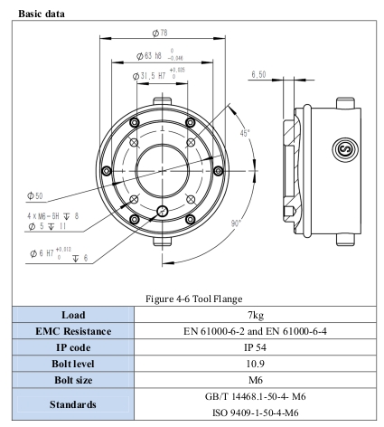
Tool installation#
The robot tool flange has four M6 threaded holes that can be used to connect the tool to the robot. These holes need to be tightened with a torque of 15N·m. If you need to adjust the tool position very accurately, you can also use Ø6 pin holes, add pins to fix. Figure 4-23 shows the pin hole positions and screw mounting positions.
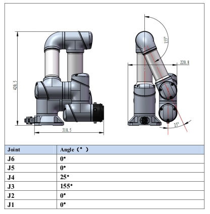
Packing posture#
The robot needs to move to a packing posture before packing. The joint angles corresponding to the packaging posture are shown in the table below.
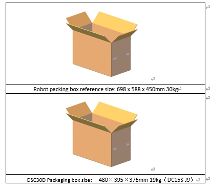
Shipping dimension#
The dimensions of the packing box provided are as follows.