Introduction#
Welding applications often require direct communication between the robot and the welder to reduce communication latency and thus achieve better weld quality.
Adaptation Instructions#
Before installing the Welding Process Package V2, you need to ensure that the robot’s software version is adapted, specifically:
Robot control software version |
V3.5.0 and up |
Robot Slave Firmware Versions |
V1.0.2 and up |
Robot Safety Controller Versions |
V2.1.0 and above |
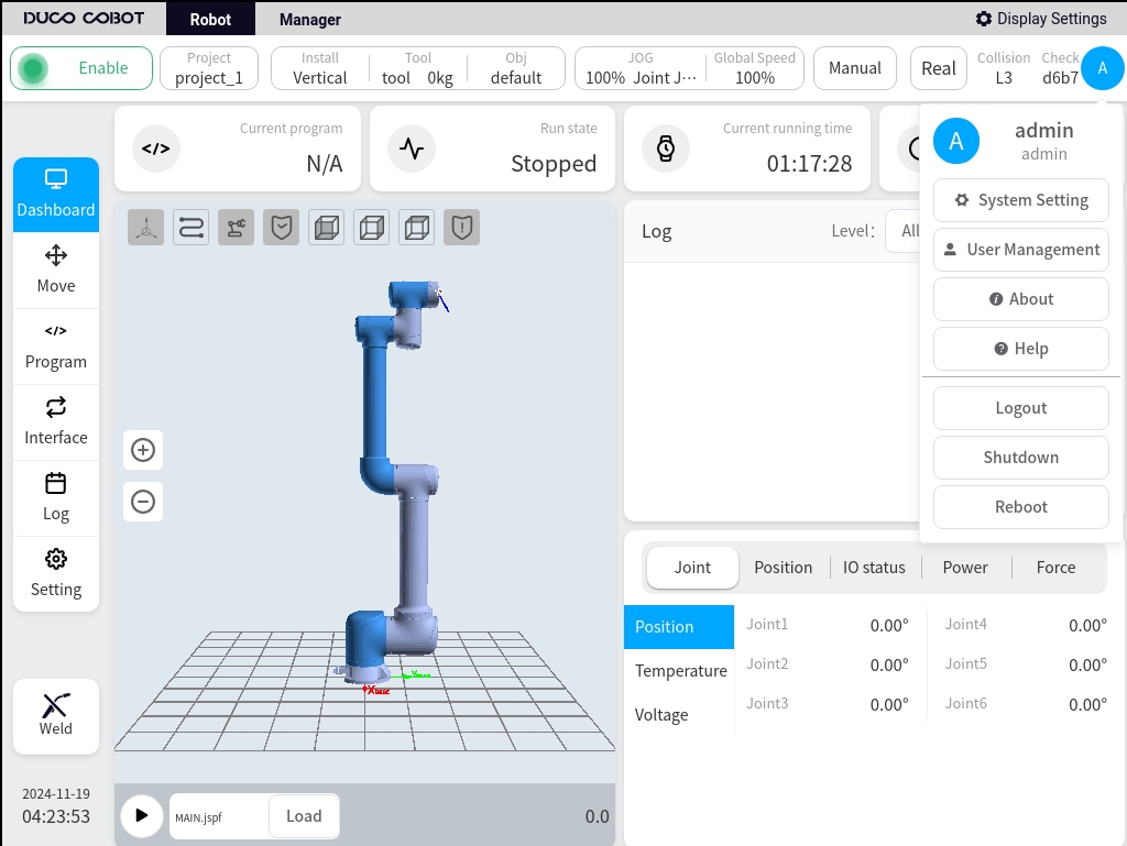
The version information of the robot can be found in the About screen after powering up the robot. To open the “About” screen, see chapter 7 of the DUCO CORE User Manual.
Welding process packages of version V2.0 and above are required to ensure that the robot’s software version is V2.7.0 and above.
The welder models supported by the current version are:
Welder connection#
When using CAN communication, you need to refer to the Collaborative Robot User’s Manual (Hardware Section), and the welder’s manual, and interface the CAN communication interface of the two. Take the example of adapting Aotai NBC-500RP Plus / NBC-350RL series welding machine:
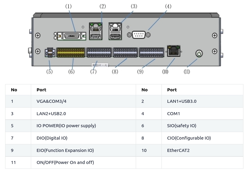
Check the Collaborative Robot User’s Manual (Hardware Section) to find the CAN communication interface, as shown below:
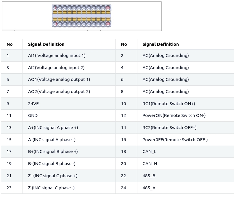
From the table, it is clear that CAN communication uses pins 11, 18, and 20.
Check the manual of the welder and find the CAN communication interface on the welder side, as shown in the following figure:
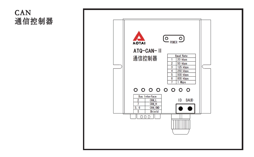
according to the instructions of the robot and the welding machine, connect the welding machine communication cable No. 2 to the corresponding line and the robot expansion interface pin 18.
No. 7 to the corresponding line and the robot to expand the interface pin 20, connect the No. 3/6 pin to the corresponding line to the robot expansion interface pin 11 to complete the wiring.
Installation and Uninstallation#
The Weld Process Package V2 plug-in package file is “weld.plugin” and the installation procedure is shown below:
Put the Welding Process Kit V2 plug-in package into a USB flash drive, the USB flash drive requires the format of FAT32.
After the robot system is started, insert a USB flash disk into the USB port on the robot control cabinet.
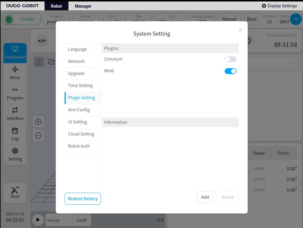
Login to the robot system using your admin account, click on the user avatar and select System Settings.
Select the plug-in management function, click the Add button.
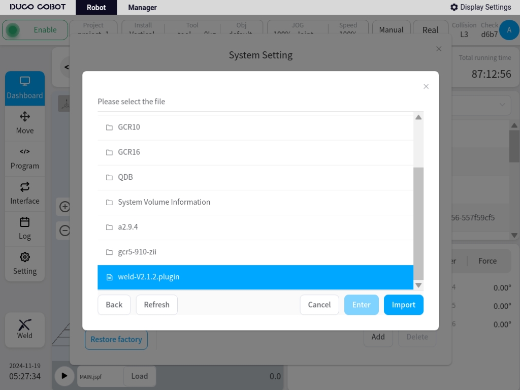
Select the USB flash drive and from the file list, find and select the “weld.plugin” package.
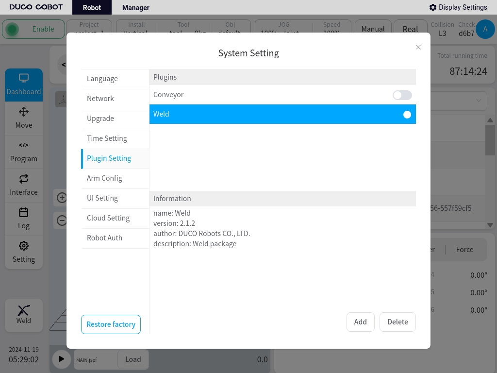
After the installation of the plug-in package is complete, as shown in the figure below, the top of the page will show a pop-up window plug-in package installation success.
And select the installed plug-ins in the region of the plug-in package, the bottom of the page details will show the name of the current plug-in package, version and other content.
After the installation of Welding Process Pack V2 is completed, the Process Pack Setup Portal will appear on the lower left side of the main page.
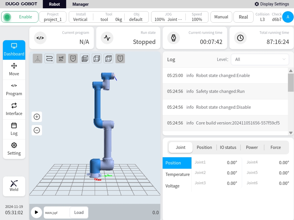
Click on this Process Kit Setup Entry button to access the Welding Process Kit V2 login page.
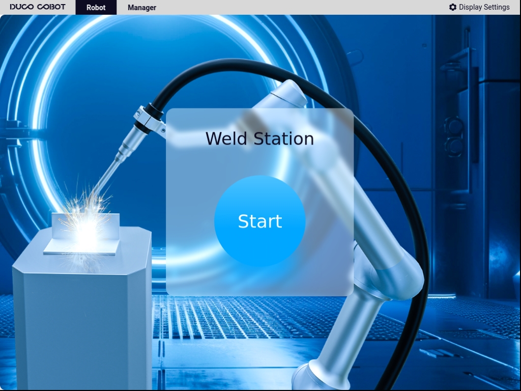
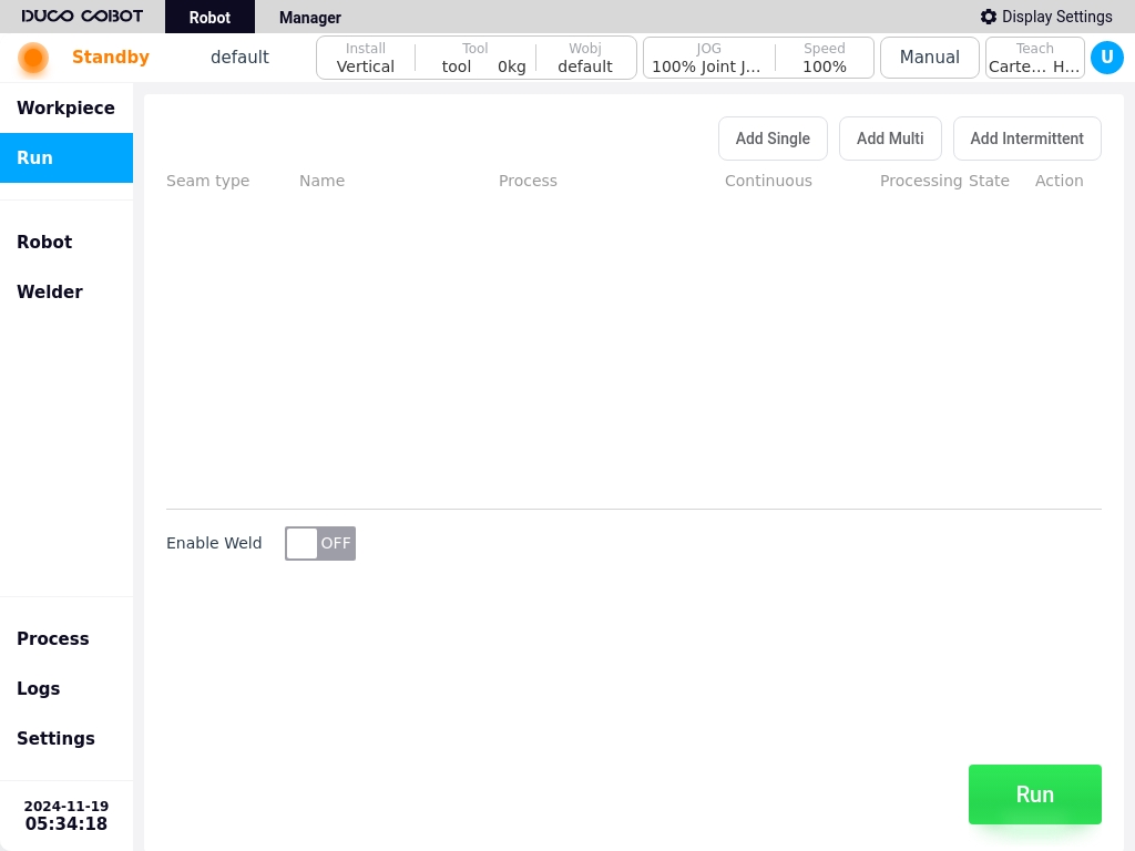
Click on the Login button to access Welding Process Kit V2 as shown below.
The installed Welding Process Package V2 can be temporarily disabled by going to the System Settings - Plug-in Settings page and turning off the enable signal.
Or click the Delete button to remove the plug-in package completely.
