Robot Programming#
When using the WeldPackage V2, it supports the implementation of the functions inside the robot programming as in version V1. This approach provides a greater degree of freedom.
Note
Calls to process libraries are not supported when used on the programming side of the robot
Starting condition#
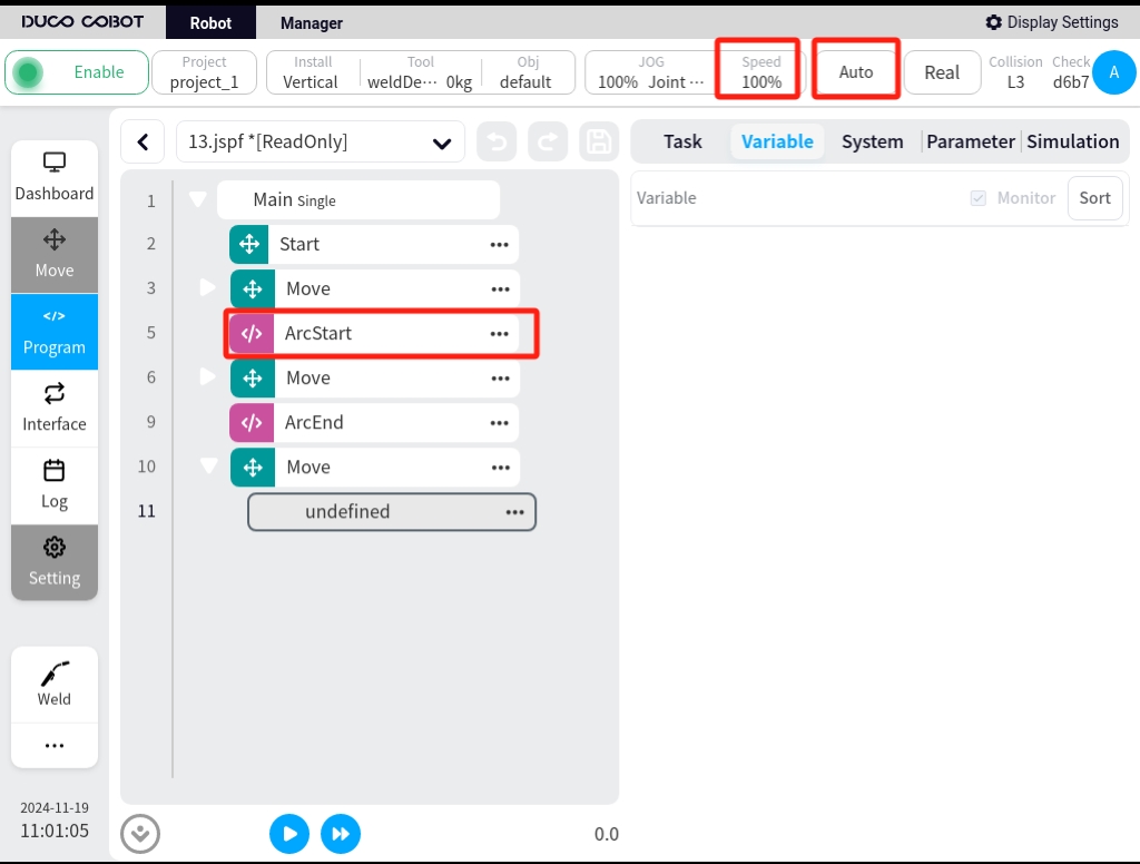
The robot sends an arc start signal to the welder, which needs to fulfill four necessary conditions.
Welding mode on
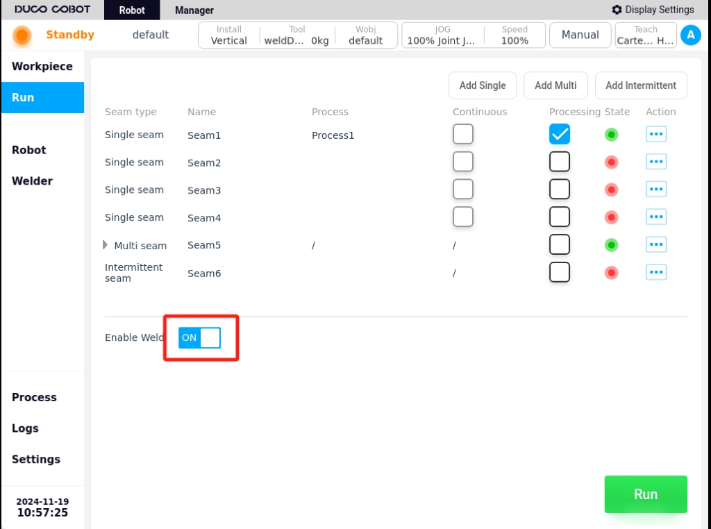
Robot motion mode is automatic mode
The global speed of the robot is set to 100%
In the robot script, there is an arc starting script
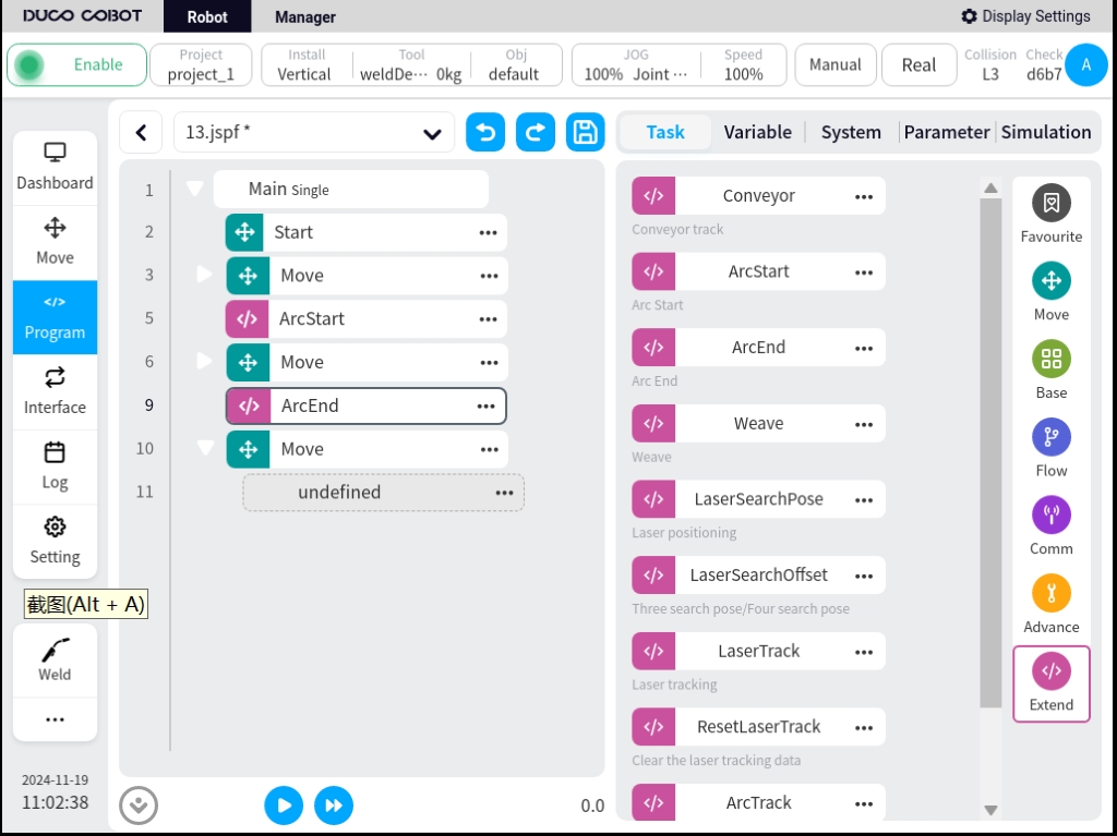
ArcStart function blocks#
Once the Welding Process Package has been installed and the Plug-in Package has been enabled, the two program function blocks, ArcStart and ArcEnd, can be seen in the Robot Program Interface, Extended Function Scripts column.
The Arc Start/Retract function block allows arc start/retract commands to be sent to the welder in two different modes. These are the mode of setting the arc start parameters and the mode of setting the JOB number. The Arc Start function block also allows for the setting of the multiplier when running empty, allowing the robot to run at high speeds when the welding mode or simulation is not turned on, so that the correctness of the welding trajectory can be quickly observed during the commissioning process. When it is necessary to change the welding parameters during the welding process while the robot is running, this can be realized by setting two ArcStart.
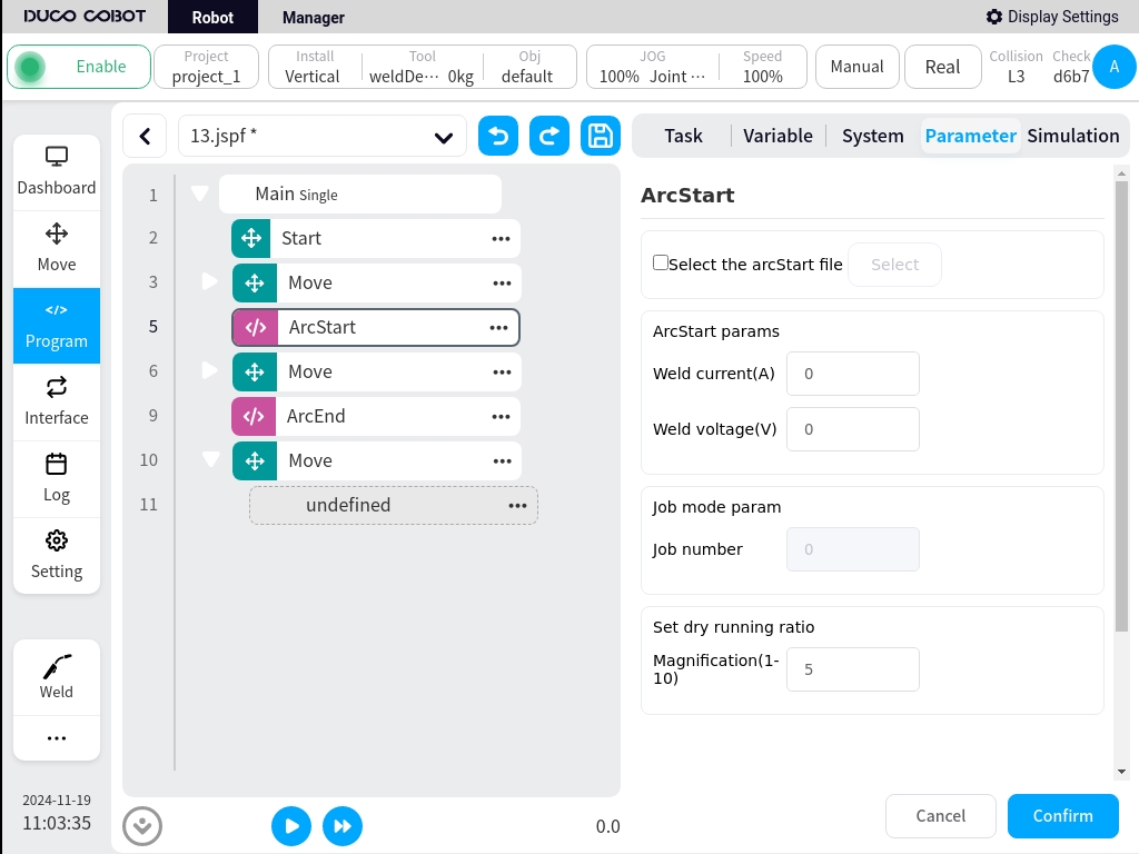
ArcStart parameters:
The welding current and voltage at arc start/close are given, and the unit of voltage is % if the control mode of the welder is set to unitary.
Job mode parameters:
To select the Job number to call, make sure the welder control mode is Job mode. When the Job mode parameter is set, the process file and arc start parameter become grayed out and cannot be edited.
Set dry running ratio:
After setting the dry running ratio, when the weld setup is set up with the air run function turned on and welder enable turned off, it will do a multiplier run for all robot motion scripts between ArcStart and ArcEnd. The actual running speed of the robot will be multiplied by the set multiplier. The calculation formula is:
Actual running speed = set weld speed * manual/automatic reduction ratio * global speed * multiplication rate
Take the example of setting the welding speed to 20mm/s, setting the global speed to 70% in manual mode, and setting the air run multiplier to 3:
The manual downsizing percentage is 25% and the automatic downsizing percentage is 100%.
Actual running speed = 10.5 mm/s.
Take the example of setting the welding speed to 20mm/s, setting the global speed to 80% in auto mode, and setting the air run multiplier to 3:
The manual downsizing percentage is 25% and the automatic downsizing percentage is 100%.
Actual running speed = 42mm/s.
Weave welding#
Version V1.2.0 and above of the Welding Process Package adds the weave function. In the “Expansion” command set in the programming interface, call the “weave” function block to enable the pendulum welding function. As shown in the figure below.
Normally, when using the weave function, it is programmed by adding a weave function block (Weave) after the existing ArcStart function block (ArcStart). In the weave, the trajectory to be welded is added. All motion commands added to the weave will have a swinging motion effect until all motion commands are completed. .. image:: ./image/10.jpg
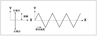
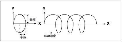
The business logic of pendulum welding is to superimpose a layer of periodic, regular pendulum trajectory on top of the original set motion trajectory. In the current version, the azimuth angle is 0° by default and cannot be set. As shown in the figure below.

Click on the weave function block to set the swing trajectory. The parameters that can be set are: trajectory type, reference plane, frequency, amplitude, OP. when choosing trapezoidal or sinusoidal trajectory, you need to add the left and right dwell time parameters.
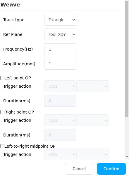
Trajectory type:
The following types are supported, Triangle, Sine, Arc, Trapezoid, Figure of 8
Note
Version 2.1 does not support custom trajectories
Triangle track: Standard pendulum welding mode. Usually used in scenarios such as large weld seams and multi-layer welding.
Sine Trajectory: Standard pendulum welding mode. Typically used in scenarios such as large weld seams and multi-layer welding.
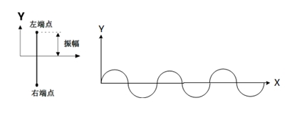
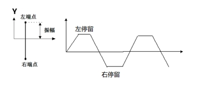
For sinusoidal trajectories, you can set the dwell time for the left and right endpoints, and you can choose whether or not to enable the main path synchronized dwells
Circular trajectory: mainly used in lap joints and cap welds with a large The circle radius is the same as the amplitude.
Trapezoidal Trajectory: Standard pendulum welding mode. Typically used in scenarios such as large weld seams and multi-layer welding.
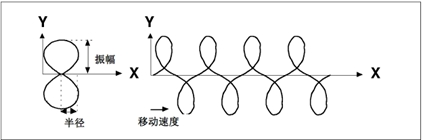
“8” trajectory: mainly in applications such as welding of thick plates and surface/external finish grinding, strength improvement, etc.
Reference plane:
Use the current tool coordinate system or workpiece coordinate system as a reference to set the plane where the swing trajectory takes effect. Supports tool XOY, tool XOZ, tool YOZ, workpiece XOY, workpiece XOZ, workpiece YOZ.
- Frequency:
The number of cycles per second that the oscillating trajectory executes.
- Amplitude:
The maximum value at which the boundary of the oscillating trajectory deviates from the reference trajectory.
- Left and right dwell times:
Used to define the length of the top and bottom edges of a trapezoidal or sinusoidal trajectory.
- Main Path Synchronized Dwell:
When the main path synchronized dwell is enabled, the robot stops moving when it reaches the ends of the sinusoidal trajectory; when the function is not enabled, the robot will continue to move in the direction of the main path when it is at the ends.
- Left endpoint OP:
Action performed when the swing reaches the left endpoint: controls the DO state and duration or triggers an event
- Right endpoint OP:
Action performed when the swing reaches the right endpoint: controls the DO state and duration or triggers an event
- Left to right midpoint OP:
Action performed when the pendulum crosses the midpoint during the movement from the left endpoint to the right endpoint: controls the DO state and duration or triggers an event
- Right to left midpoint OP:
Action performed when the pendulum crosses the midpoint during the movement from the right endpoint to the left endpoint: controls the DO state and duration or triggers an event
Arc tracking#
Arc tracking is mainly used in thick plate welding, where the welding trajectory of the robot is compensated by detecting the value of the current flowing between the wire and the processed workpiece during the welding process.
Compensation is only possible in the up and down direction and the left and right direction, and only in sinusoidal pendulum welding.
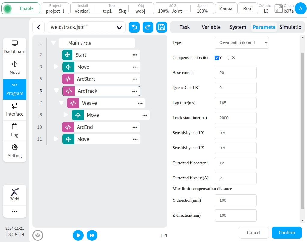
Arc tracking command: ArcTrack
Configuration parameters are:
Type: Used to set the type of arc tracking, with the following options:
End clearing path information, offset information for clearing records at the end of the trace
End retention path information, offset information for records retained at the end of the trace
Use the recorded path information to trace using the offset information from the last trace record (mainly used for multi-layer multi-pass welding)
Compensation direction: Select the direction to enable the compensation function, Y (left and right direction), Z (up and down direction). For sinusoidal pendulum welding, you can choose to enable Y and Z direction compensation, while other types can only enable Z direction compensation.
Reference current: Reference current value
Current-height scale factor: the scale factor of welding current and torch height, default value 4
Maximum Compensation Distance Limit: Maximum allowable offset of the left, right, up and down directions relative to the trajectory.
Multi-layer multi-pass welding#
Welding Process Package v1.4 and above, DUCO Core v2.9.0 and above
Welding of medium-thick plates often requires multiple welds on the same part to increase the weld width. The main principle is: record the trajectory of the first weld and the compensation amount; based on the recorded compensation amount, add the overall offset to realize the operation of the subsequent weld pass.
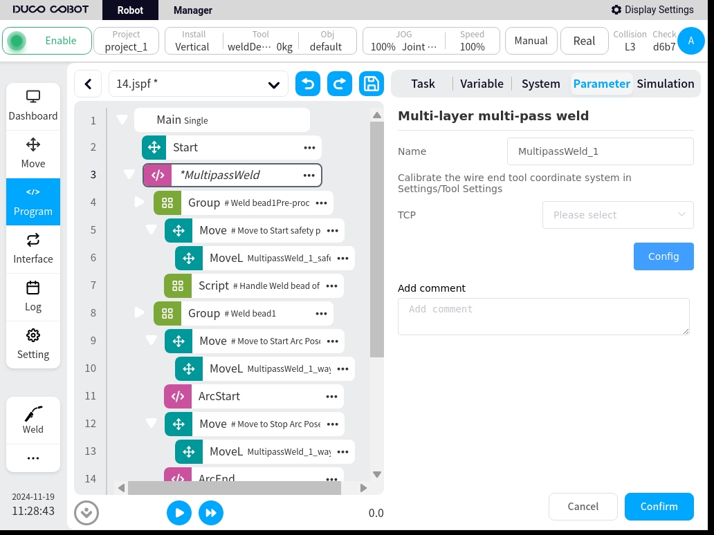
This process package provides a MultipassWeld function block to guide the user through the programming of a multi-layer, multi-pass welding operation.
On the programming page, in the command “Extensions”, look for the “MultipassWeld” function block. Add it to the program, click on it, and the configuration page will look like this
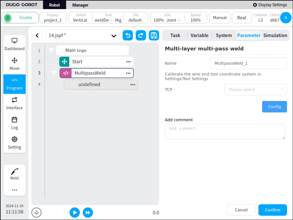
Configure the tool coordinate system: Teach the tool coordinate system with the end of the wire in the setup page.
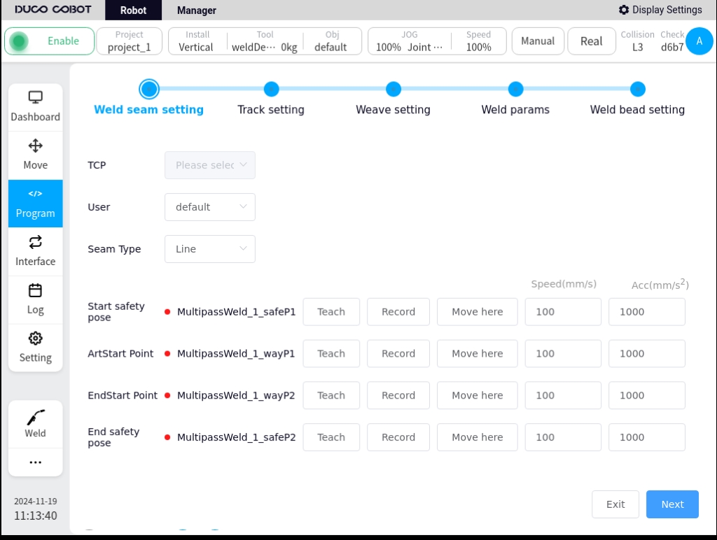
Click on Parameter Configuration to enter the Multilayer Multi-Pass Welding Guidance Configuration page. It is divided into the following steps, which can be switched by clicking Next or clicking on the navigation menu above.
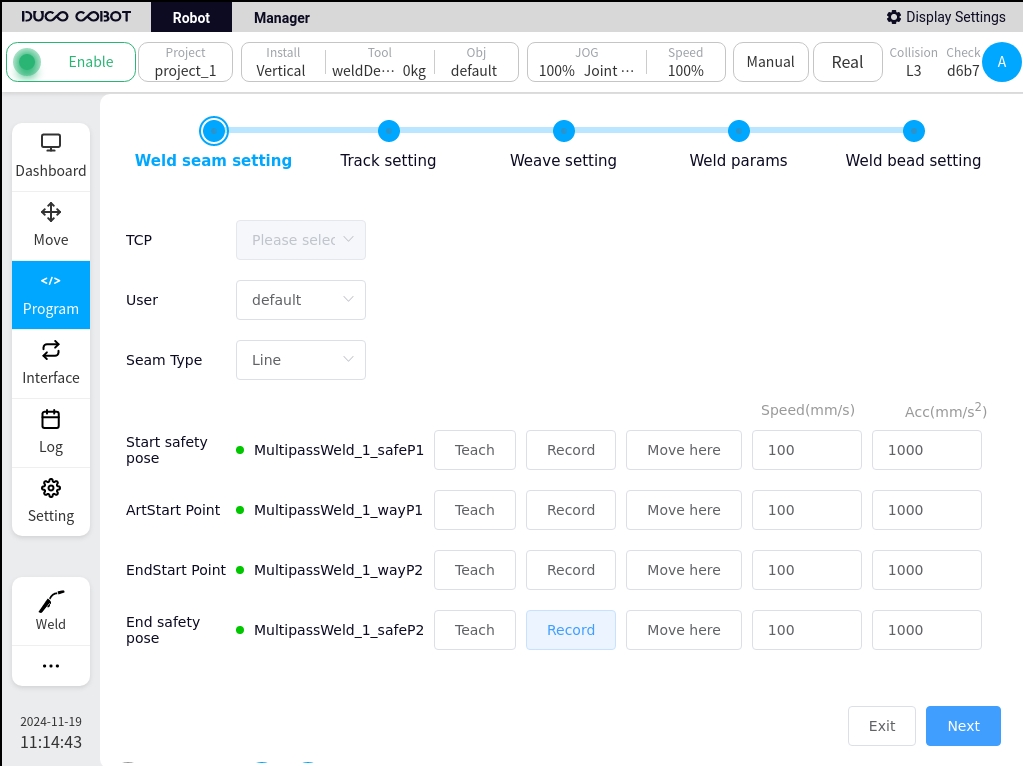
Weld configuration
Configuration of the initial weld’s point positions, mainly the workpiece coordinate system, the weld’s start safety point, the start point, the end point, and the end safety point. It is possible to teach the coordinates of the points as well as the speed and acceleration of each point.
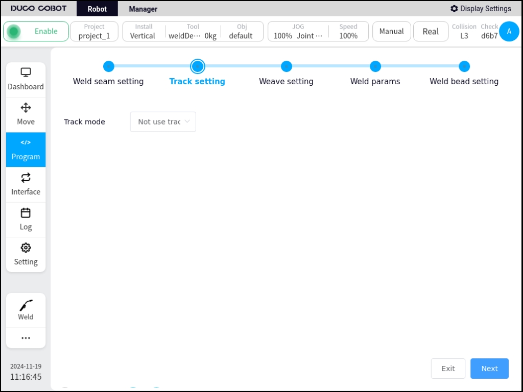
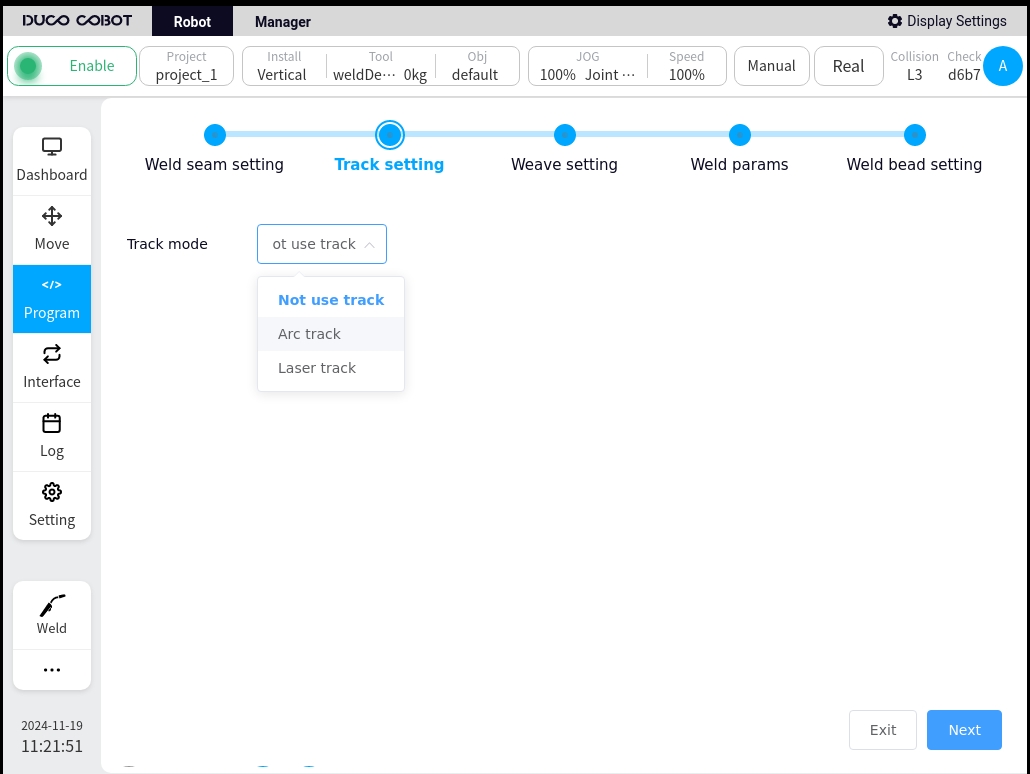
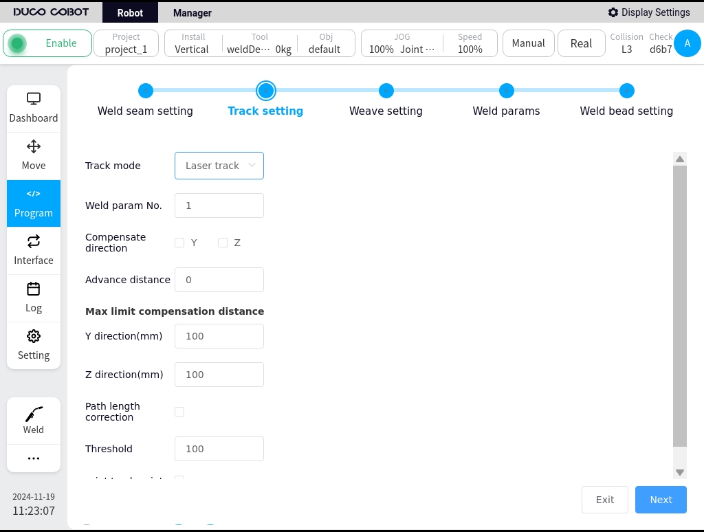
Tracking settings
Configure whether the weld uses tracking or not, you can choose not to use tracking, use arc tracking, or use laser tracking. When arc tracking is selected, the configuration parameters are detailed in section 5.4, Arc Tracking, and when laser tracking is selected, the configuration parameters are described in section 7.7, Laser Tracking.
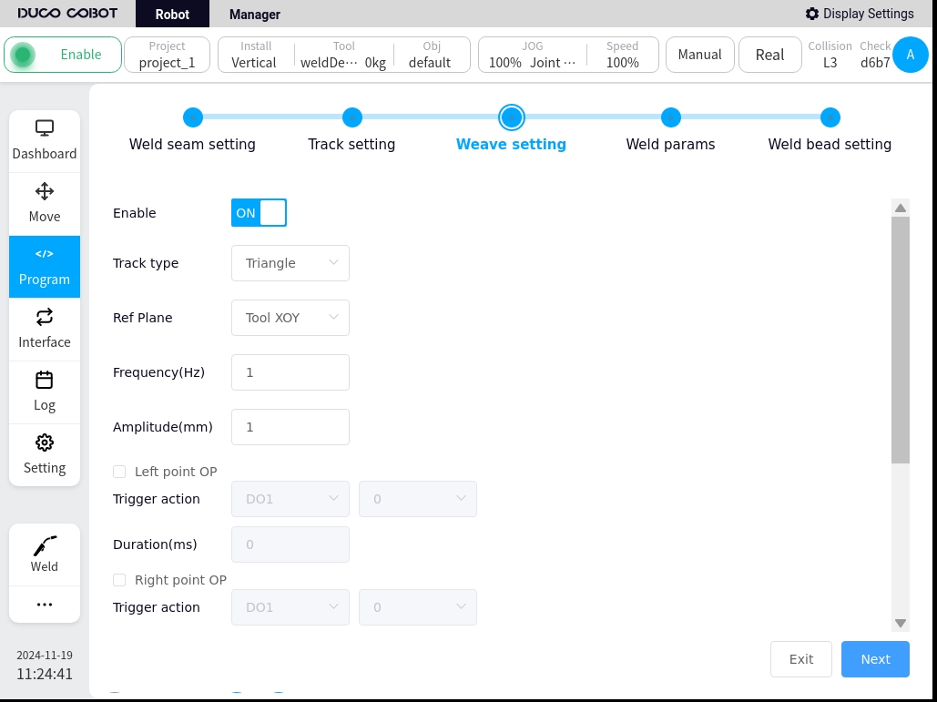
Pendulum welding setup
Select whether to enable pendulum welding, configure the type of pendulum welding, reference plane, frequency, amplitude, OP, etc. The specific configuration parameters are detailed in Section 5.3, “Pendulum Welding”.

Welding parameters
Configure the welding parameters, welding current, voltage, JOB number, etc. Specific configuration parameters are detailed in Section 5.2, Arc Start/Retract Function Block

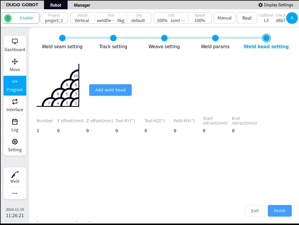
Welding channel setup
Configure the offset, indentation, tool attitude, etc. for each subsequent weld pass, and add up to 9 passes.
The parameters of the weld channel are:
Y offset: Y of the tool coordinate system
Z offset:
Tool-RY: the rotation of the tool in the Y direction of the tool’s reference tool coordinate system.
Tool-RZ: the rotation of the tool in the Z direction with reference to the tool coordinate system.
Path-RX: the amount of rotation of the tangent to the path at the start of the tool’s reference path coordinate system (for a straight line, i.e., the amount of rotation in the direction of the reference path)
Starting point indentation: the distance that the starting point of the weld is indented in the direction of the path.
End point indentation: the distance that the end point of the weld is indented in the direction of the path.
The default pendulum welding parameters, welding parameters, etc. for individual weld passes are the same as for the initial weld. You can set the parameters for individual weld passes individually by clicking the Edit button.
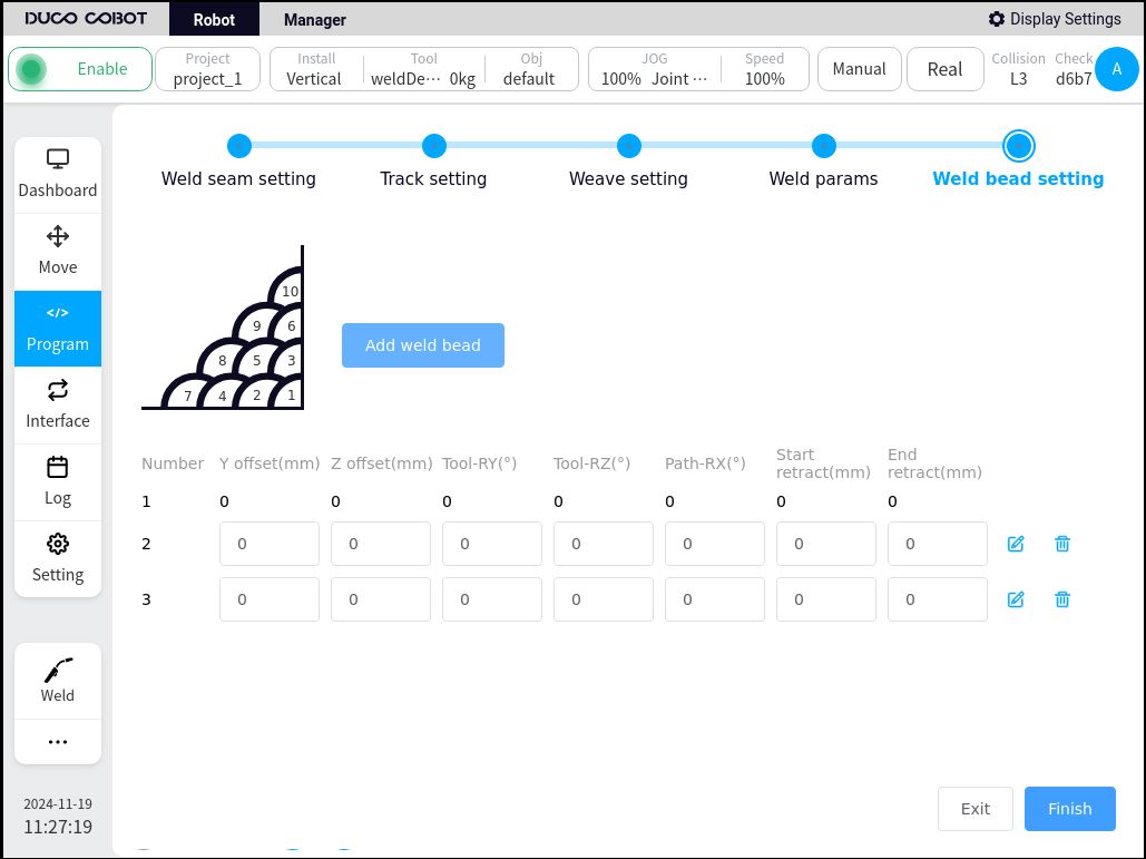
Detailed configuration of welding channels
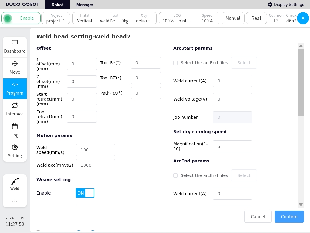
After the configuration is complete, click OK to automatically generate the program block. Note: The generated block cannot be edited with separate parameters, if you need to change the parameters, please set them in the parameter configuration of the MultipassWeld block.