Laser tracker#
Introduction#
The laser tracker recognizes the weld seam by acquiring laser images and obtaining features of the weld seam. The robot acquires the feature information it recognizes and realizes automatic monitoring and correction of the weld seam. In practical application, it can solve the problems of workpiece placement error, poor workpiece consistency, and weld seam deformation caused by welding heat.
The welding process package supports laser position finding and laser tracking functions.
laser communication link#
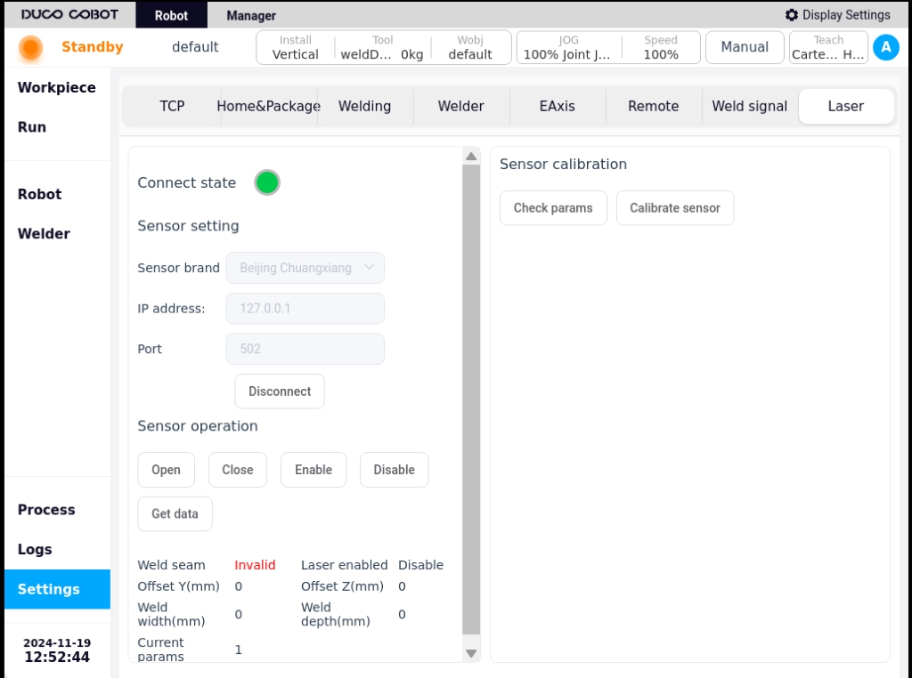
Use a network cable to connect the network port on the robot control cabinet to the laser sensor, and configure the IP address of the robot to the same network segment as the IP of the laser sensor. Enter the IP and port number of the laser sensor as shown and click Connect. The connection status will be displayed when the connection is successful. The connection settings for each manufacturer are as follows
Beijing CRNT:
You need to set the protocol of the laser to Modbus first using the Creative’s host computer. connection port number 502
Tangshan Yinglai:
The port number is set to 5020.
Suzhou FullVision:
The port number is set to 502
Laser sensor control
The laser sensor can be operated manually to turn the laser on/off and acquire the data detected by the laser.
laser calibration#
The calibration of the laser sensor is used to calculate the positional relationship between the robot TCP and the sensor. That is, based on the results of the calibration calculation, the feature points recognized by the laser can be converted to their position in the robot coordinate system.
Calibration preparation:
Install the welding torch and adjust the length of the welding wire to the length used during the welding operation.
Install the laser sensor according to the installation requirements of the laser sensor and the site conditions.
Prepare the spikes to be used for calibrating the robot TCP.
prepare switches and other network equipment to connect laser sensors, laser sensors used by the host computer, the robot, set it in the same network segment, to ensure that the normal communication
Make sure that the laser image is visible on the laser sensor’s host computer.
Verify that the laser switch and data acquisition work properly in the sensor setup page of the robot welding process kit.
Calibration process:
Tool (TCP) calibration, that is, calibration of the position of the end of the wire, at this time the length of the wire is the actual welding wire length. Calibration method see basic settings / TCP calibration
Set the calibrated TCP as the current TCP
Take a marking point on the weld seam, move the robot so that its TCP is aligned with the marking point, and click record.
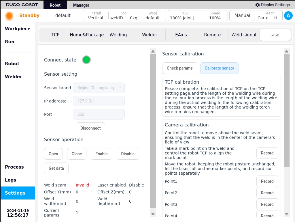
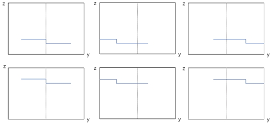
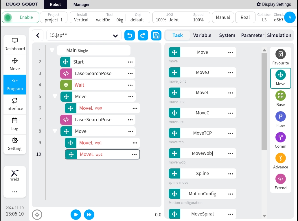
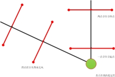
keep the robot attitude unchanged, turn on the laser, turn on the enable, move the robot, let the laser fall on the marking point, observe the laser image on the laser software in the marking process, in turn, make the laser image for the six states in the following figure, record the point 1-6
Click Calibration Calculation, the calibration error and calculation result will be displayed below. If each value is less than 1mm, the calibration is valid, otherwise recalibrate.
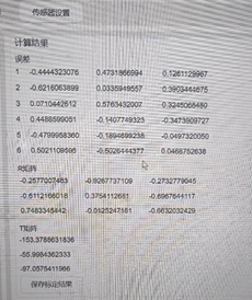
Click Save Calibration Results to save the calculation results. Note: The calculation results are stored in the current project of the robot, so it is recommended to save the project at this time to prevent loss.
Attention:
Robot TCP needs to be calibrated before calibration to ensure calibration accuracy
Before calibration, set the calibrated tool coordinate system as the current one.
When recording 7 points, the length of the welding wire is consistent with the calibration of the TCP and also with the length of the welding wire during the welding process.
When recording 7 points, the robot’s attitude cannot be changed
Ensure that the laser image detection is stable when recording the 7 points.
Calibration accuracy verification
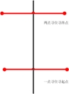
After calibrating the sensors and the robot, the accuracy of the calibration can be verified using single point seek.Write the following program, using the function blocks LaserSearchPose and MoveL. LaserSearchPose will turn on and enable the laser, obtain information about the position of the feature point recognized by the laser, convert it to its value in the robot’s base scale system, and assign the value to a variable. moveL moves to the variable. Run the program to check if the robot TCP moves to the recognized feature point.
Note
Note: Please make sure that the TCP at this time is the TCP used for the above calibration.
Programming function blocks#
There are three function blocks associated with the laser sensor: LaserSerachPose, LaserSearchOffset, and LaserTrack.
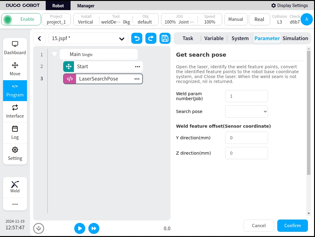
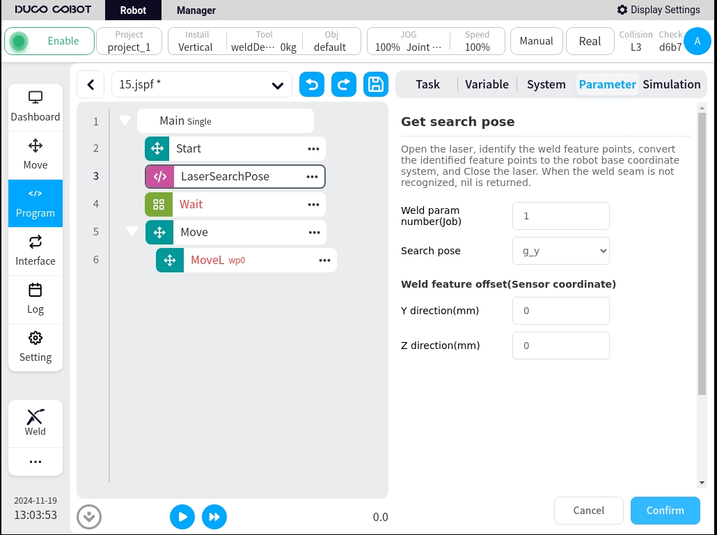
LaserSearchPose
It is mainly used to obtain the position of the feature point recognized by the laser under the base coordinate system of the robot. This function block encapsulates the following operations: select the Job number to be used, turn on and enable the laser, get the position information of the feature point recognized by the laser, get the value of the current TCP of the robot under the base coordinate system, calculate the position information of the feature point under the base coordinate system of the robot according to the calibration relationship, and assign the value to the pose type variable. If no weld seam is detected, return nil.The configuration page is as follows
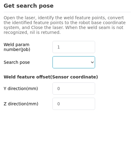
Weld Mode Parameters: i.e. Job number, a set of parameters set and saved at the laser tracker end: e.g. weld type, exposure, detection capability, etc.
Finding site: the result of a calculation that can be associated with a variable of type pose
Weld feature point offset: add an offset to the recognized feature point and calculate the position after point conversion after the offset. It can be used to deal with robot error, mismatch between inspection point and welding process, etc. (If the laser tracker provides the function, it can also be set at the laser tracker side)
LaserSearchOffset
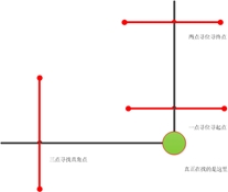
It is mainly used to calculate the position of the coordinate system obtained by three-point or four-point seeking.
The configuration page is as follows
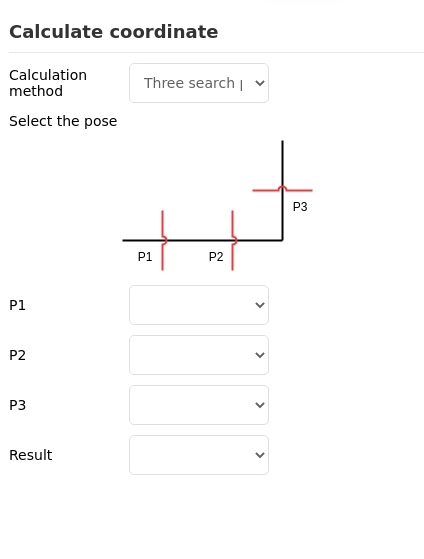
The following settings are available
Calculation method: choose three-point or four-point search
Select Points: Associated Points Information
Result: the result of the calculation, associated to the pose type variable
LaserTrack
Realization of laser tracking function.
The main realized functions: turn on and enable the laser, set the Job number used by the laser, set the compensation direction and advance distance, acquire the characteristic points of the weld seam in real time, calculate the deviation and compensate it to the actual trajectory.
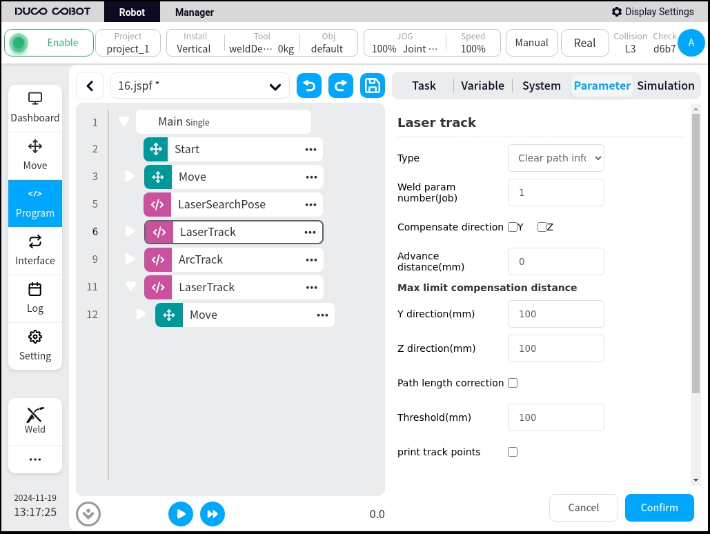
The configuration page is as follows
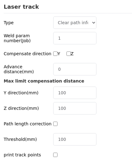
The following settings are available
Weld pattern parameters: Job number
Compensation direction: Select whether to enable compensation in Y or Z direction.
Advance distance: Set the distance between the laser line and the welding torch in mm.
Maximum compensation distance limit: Maximum permissible deviation of the taught trajectory from the laser-measured trajectory
Weld feature point offset: offset is added to the recognized feature point (can also be set on the laser tracker side if the laser tracker provides the function)
Script#
The following scripts are added to the welding process package and can be called when programming with scripts
Turn on the laser.
_plugin_weld.open_laser()
Turn off the laser.
_plugin_weld.close_laser()
Enable Laser (Required for Creation Laser Sensor Recall)
_plugin_weld.enable_laser()
Down Enable Laser (Required for Creation Laser Sensor Recall)
_plugin_weld.disable_laser()
Setting the weld type parameter (Job number)
_plugin_weld.set_laser_weld_type(type)
Position searching, the function is the same as LaserSearchPose function block, turn on the laser, get the feature point of the weld seam, calculate its position in the robot coordinate system, turn off the laser.
_plugin_weld.search_pose(pose, offset)
pose: pose type, robot TCP pose, in m, rad
offset: number_list type, offset of weld feature point {y, z}, default {0, 0}, unit: mm
Return value: pose type, the position of the feature point in the robot’s coordinate system, in m, rad, nil means no weld is detected
Similar to search_pose, the laser is not switched on and off, the weld feature points are acquired and their position in the robot coordinate system is computed
_plugin_weld.get_laser_search_pose(pose, offset)
pose: pose type, robot TCP pose, in m, rad
offset: number_list type, offset of weld feature point {y, z}, default {0, 0}, unit: mm
Return Value: Pose type, the position of the feature point in the robot coordinate system, in m, rad, nil means no weld is detected.
Acquisition of raw laser data
_plugin_weld.get_laser_raw_data()
Returns the following array {status, y, z, width, depth}, which represents
status: boolean indicates whether a weld is detected or not
y: number, Y-coordinate of the weld feature in mm.
z: number, z-coordinate of the weld feature in mm.
width: number, width of the detected weld in mm.
depth: number, depth of the detected weld in mm.
Laser positioning#
single-point seeker (computing)
Suitable for applications such as spot welding
A programming example is shown below:
two-point searches
Suitable for applications such as intermittent short welding
An example of programming is as follows
Three-point seeker/four-point seeker
The basic principle is that a workpiece coordinate system is established based on the point position of the laser positioning, and the deviation from the original workpiece coordinate system is calculated to obtain the offset of the weld seam on the workpiece. It can be used for welding complex structural parts. Four-point positioning is better than three-point positioning to deal with the incoming material error and assembly error of the workpiece.
The following is a demo of three-point seeking, and four-point seeking is similar to three-point seeking.

Variable Definition
variable name |
type |
|
|---|---|---|
P1 |
pose |
first search point |
P2 |
pose |
second search point |
P3 |
pose |
third search point |
teach_pose |
pose |
result of three-point seek computation |
g_enable_offset |
boolean |
Controls the operation of the program. When false, it is used to do |
g_base_pose |
pose |
computed initial artifact coordinate system |
g_pose |
pose |
result of three seek calculations |
g_offset |
pose |
deviation from initial coordinate system |
Program description
Three rows, first locus.
5 line seek, get the seek result, save in variable p1
6 rows, second locus.
8 line seek, get the result of the seek and save it in the variable p2.
9 rows, third locus.
11 line seek, get the seek result, save it in variable p3
12 rows Three-point position finding, calculating the coordinate system determined by p1,p2,p3, stored in the variable teach_pose
Lines 13-16 If variable g_enable_offse is false, assign the value of teach_pose to g_base_pose; otherwise, assign the value to variable g_pose
17 lines Execute subsequent procedures when g_enable_offset is true
18 line script Calculate the deviation of the coordinate systems of g_base_pose and g_pose using pose_offset() and assign the result to the variable g_offset
20 lines Add g_offset as a coordinate system offset to the current coordinate system
Rows 21-24 Actual work points, using the workpiece coordinate system.
The actual use process is as follows:
Instruct the robot to determine the laser’s seeking point
Set up the workpiece, set the value of g_enable_offset to false, and run the program.
Check the value of g_base_pose in the variable area, create a new workpiece coordinate system wobj1, and use the value of g_base_pose for the workpiece coordinate system.
Set wobj1 as the current workpiece coordinate system, and use this coordinate system as the reference to teach the workpiece’s trajectory, i.e., the points in lines 22-24.
Set the value of g_enable_offset to true, run the program, and execute the normal workflow.
The above demo uses a workpiece coordinate system, and by performing the three-point positioning calculation for the first time, an initial workpiece coordinate system is obtained, based on which the work points are taught. It is guaranteed that if the workpiece is shifted due to placement, etc., the deviation of the coordinate system obtained by three-point positioning from the initial coordinate system can be calculated, and the deviation can be added to the workpiece coordinate system so that the trajectory can adapt to the change.
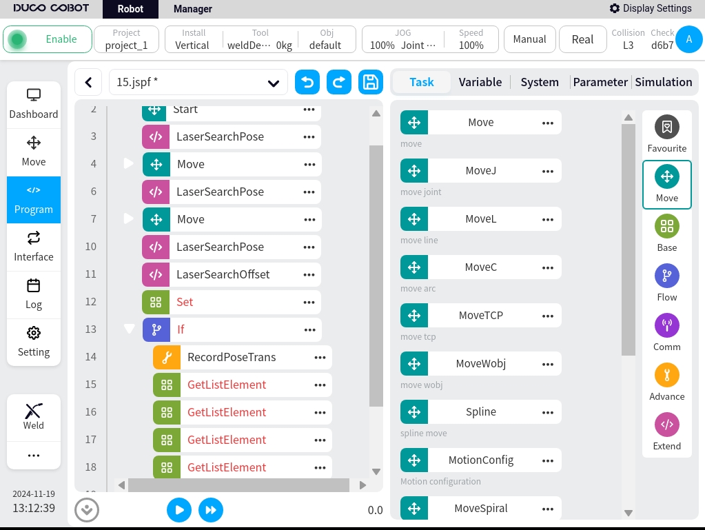
Since this Demo needs to set up the coordinate system of the workpiece, in some cases the demonstration needs to switch the coordinate system frequently, which may be cumbersome. You can refer to the following Demo, which uses the RecordPoseTrans function block, and can all be programmed based on the base coordinate system.
Variable Definition
variable name |
type |
|
|---|---|---|
P1 |
pose |
first sought site acquired |
P2 |
pose |
Acquired second seek site |
P3 |
pose |
Acquired third seeker site |
teach_pose |
pose |
result of three-point seek computation |
g_enable_offset |
boolean |
Controls the operation of the program. When false, it is used to do |
g_base_pose |
pose |
computed initial artifact coordinate system |
g_result_list |
pose_list |
position of the actual operating point in the base coordinate system |
g_way_pose1 |
pose |
first job point |
g_way_pose2 |
pose |
second job point |
g_way_pose3 |
pose |
third job point |
g_way_pose4 |
pose |
fourth_operation_point |
Program description
Three rows, first locus.
5 line seek, get the seek result, save in variable p1
6 rows, second locus.
8 line seek, get the result of the seek and save it in the variable p2.
9 rows, third locus.
11 line seek, get the seek result, save it in variable p3
12 rows Three-point position finding, calculating the coordinate system determined by p1,p2,p3, stored in the variable teach_pose
Line 13 Assign teach_pose value to g_pose
14 lines Execute subsequent procedures when g_enable_offset is true
15 lines The operation point teaches the conversion and saves the result in the variable g_result_list.
Lines 16-19 Get each point from g_result_list and assign it to each job point variable
20-24 Lines Execute the actual job, with points using the individual job point variables.
The actual use process is as follows:
Teach the robot to determine the laser’s search point.
Set up the workpiece, set the value of g_enable_offset to false, and run the program.
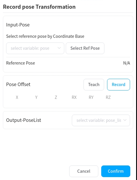
in the variable area to view the value of g_base_pose, open the RecordPoseTrans function block, as shown in the figure, in the input reference position, select the variable g_base_pose, click on the “set to the base” button, the base position at the base position will display the value of the base position at this time.
In the operation point offset, teach the addition of operation points, and in the output, select a pose_list type variable to store the results of the calculated operation points.
Set the value of g_enable_offset to true, run the program, and execute the normal workflow.
In contrast to the previous demo, variables are used as actual job points, and the points are calculated by RecordPoseTrans. The coordinate system obtained from the first use is used as a reference to teach each work point position and is added to the RecordPoseTrans block. If the workpiece is subsequently shifted, the RecordPoseTrans function block calculates the value of each job point in the base coordinate system based on the coordinate system calculated by the position finding.
Laser tracking#
When it is necessary to detect changes in the weld seam in real time during the welding process, the laser tracking function is used.
example
Program description
4 rows. Robot turns on tracking at point wp1.
5 rows Starting point seeks bits and puts the result in the variable start
6 lines Turn on tracking, do not turn off tracking at end of setup
Row 7. Move to the start of the arc.
Row 9. Arc up.
10 lines Enable tracking, disable tracking at end of setup
Row 11 Teach a primitive trajectory wp0
The robot will perform the following operations, turn on and enable the laser, acquire the arc start point, turn on tracking and move to the arc start point, start the arc, turn on tracking, calculate the deviation from the taught trajectory based on the feature points obtained from the real-time acquisition laser sensor, and compensate the deviation to the taught trajectory, so that the robot TCP will run in accordance with the detected weld seam.
Error Handler#
Weld with or without inspection
LaserSearchPose can determine whether its return value is nil to determine whether the weld is detected. Examples are as follows:
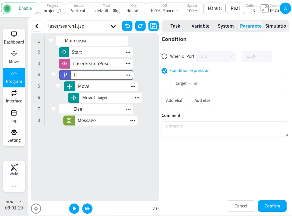
LaserSearchPose puts the seek result in the variable target, If the condition determines whether target is nil to execute the logic when a weld is detected and not detected.
Three/four-point seeker position deviation over-protection
In some cases the weld may be detected incorrectly, resulting in an excessive deviation from the calculated workpiece coordinate system, and a deviation limit can be added to prevent safety issues such as gun bumping.
Examples are shown below:
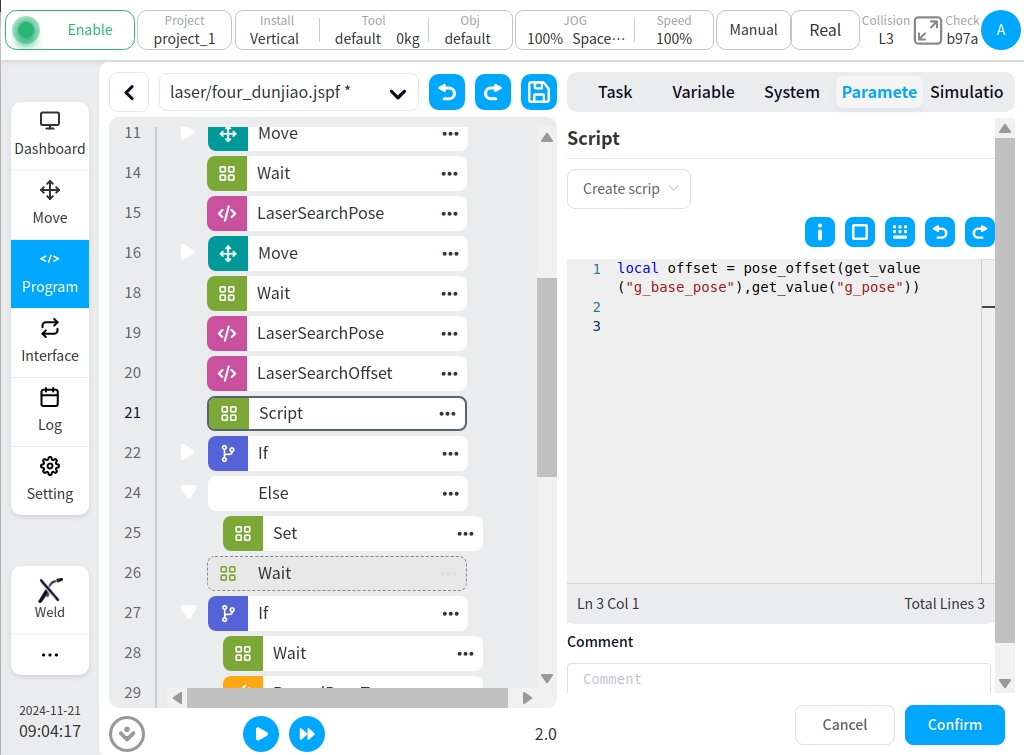
The Script function block uses the pose_offset script to calculate the deviation between the original and the newly computed coordinate system, adding execution logic to determine if the deviation is greater than a certain range.