External Axis Configuration#
The External Axis Configuration sub-page is used for external axis communication settings, axis configuration, and program configuration, as shown below.
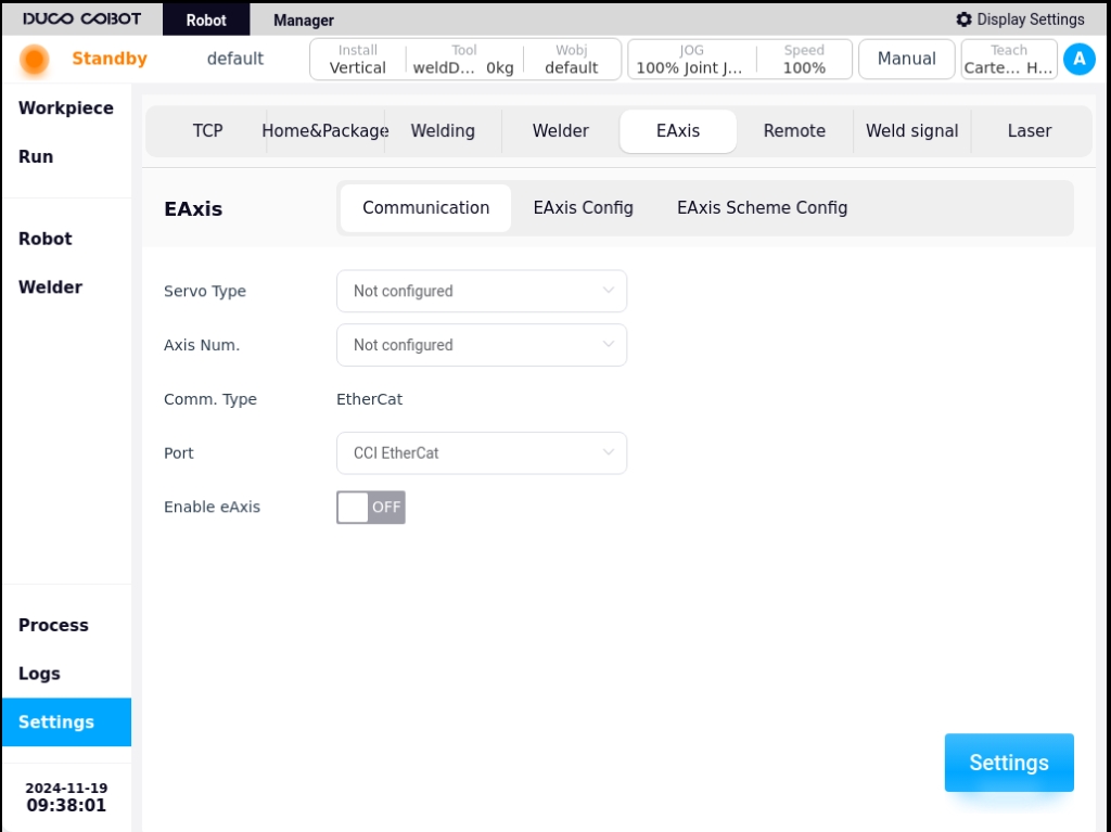
1. Communication settings#
The communication settings page allows you to configure the servo model, number of axes, input port, and display the communication method. The servo model and axis number are not configured by default, the input port is only the Ethercat port of the control cabinet at present, and the communication mode is Ethercat by default.
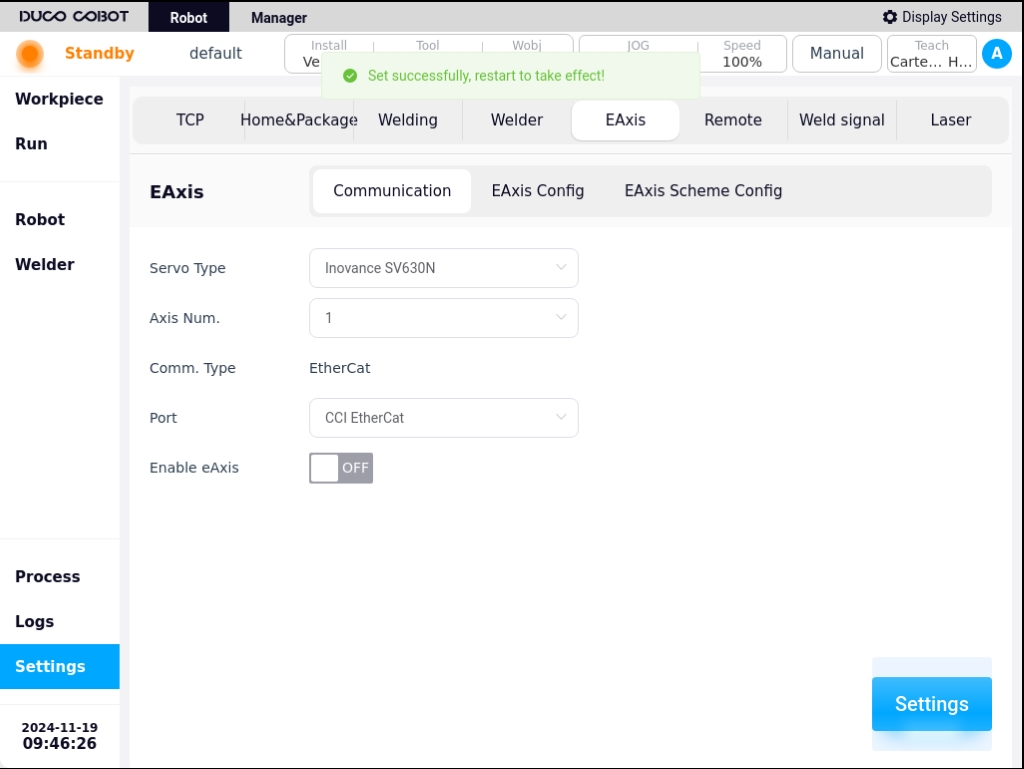
Choose to configure the servo model, the number of axes, as shown in the figure below, and then click on the “Settings” button, a pop-up message “Setting is successful, restart the control cabinet to take effect! The message will pop up “Setting is successful, restart the control cabinet to take effect!”.
If the topology configured by the user is different from the topology currently in effect on the system, click the “Set” button and a pop-up box will appear in the interface, as shown in the following figure:
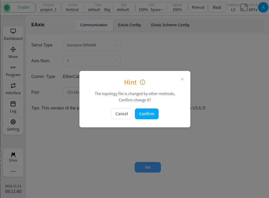
If you do not want to modify the topology currently stored in the system, click the “Cancel” button; if you confirm the modification, click the “Confirm” button.
2. Shaft configuration#
The Axis Configuration page displays basic information such as axis name, axis type, axis position, etc. It allows you to perform point-to-point movement of the axis position, enable or disable operation of the axis, as well as configuration of the axis parameters. One external axis corresponds to one actual single-degree-of-freedom servo unit.
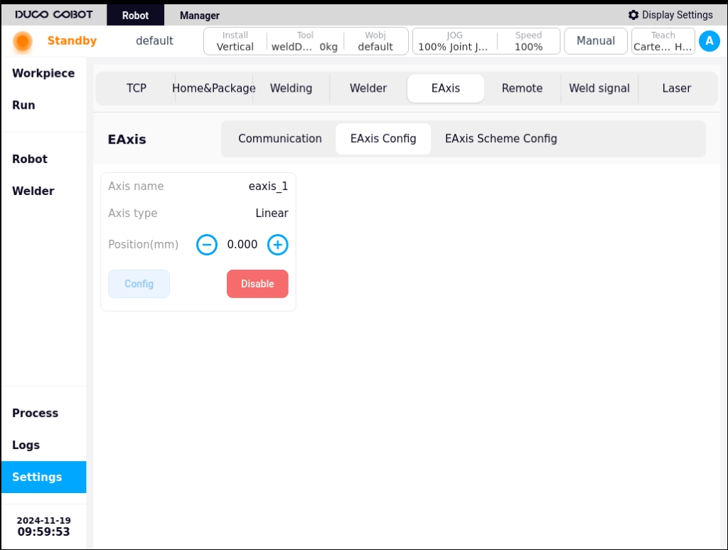
When the external axis is enabled by clicking the Enable button, the external axis can be moved in the reverse or forward direction by pressing and holding the left  icon or the right
  icon on the axis position display.
Note
Note: When the external axis break is enabled, no axis pointing operation can be performed.
Click the “Configuration” button, the external axis parameter configuration pop-up box will appear as shown in the figure below, the configurable parameters are axis type, axis control mode, reference speed, reference acceleration, The configurable parameters are axis type, axis control mode, reference speed, reference acceleration, maximum speed, maximum acceleration, encoder type, encoder resolution, zero offset, guide range, direction of motion, upper limit position, lower limit position.
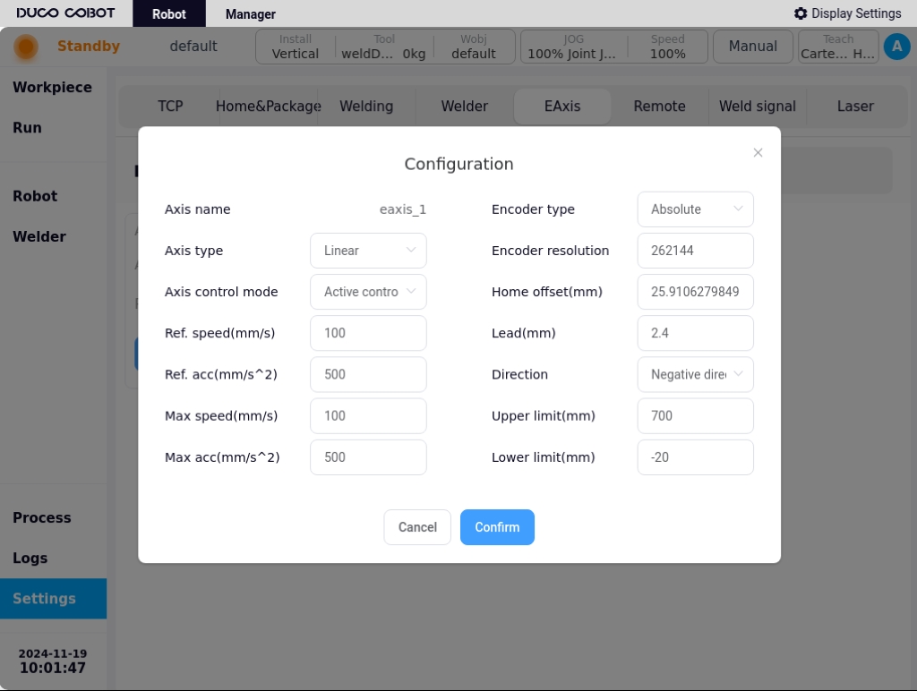
Parameter description:
Axis type: Linear guides or translators;
Axis control modes: active control mode or cooperative control mode. In active control mode, the external axes are directly generated and controlled by the robot controller for planning instructions; In cooperative control mode, the external axes are controlled by independent controllers and communicate with the robot controller, and the robot carries out cooperative control based on the external axis commands. The robot maintains a specific relationship with the external axis coordinate system;
Reference speed: This speed will be used as a reference speed in mm/s or °/s for external axis pointing movements;
Reference Acceleration: This acceleration will be used as the reference acceleration in mm/s^2 or °/s^2 for the pointwise motion of the external axis;
Maximum speed: This speed will be used as the maximum speed constraint and monitoring parameter in mm/s or °/s for the joint planning of movements of external axes;
Maximum Acceleration: This acceleration will be used as a parameter for acceleration constraints and monitoring during the joint planning of the movement of the external axes, in mm/s^2 or °/s^2;
Encoder type: incremental or absolute;
Encoder resolution: a dimensionless parameter used to convert the number of encoder communication data cnt into a scale factor of the actual angle value, encoder cnt/number of encoder bits = actual angle;
Zero Offset: only shows configurable and effective if the encoder type is absolute, default is 0, unit is mm or °, user can modify it directly or quickly by setting the current position as zero position;
Lead: Configurable and valid only if the external axis type is a linear guide, in mm, describes the displacement distance generated by the linear guide when the encoder is rotated by 360°, encoder cnt/encoder position * lead = actual position of the linear guide;
Direction of motion: Forward or reverse, describes the relationship between the encoder’s increasing direction and the actual shaft’s direction of motion, forward is the same direction, reverse is the opposite reverse;
Upper limit/lower limit: to describe the absolute range of motion of the external axis with reference to the current zero position, exceeding the limit will trigger the corresponding safety stop operation in mm or °.
Note
Note: Configuration of external axis parameters is not possible after the external axis is enabled.
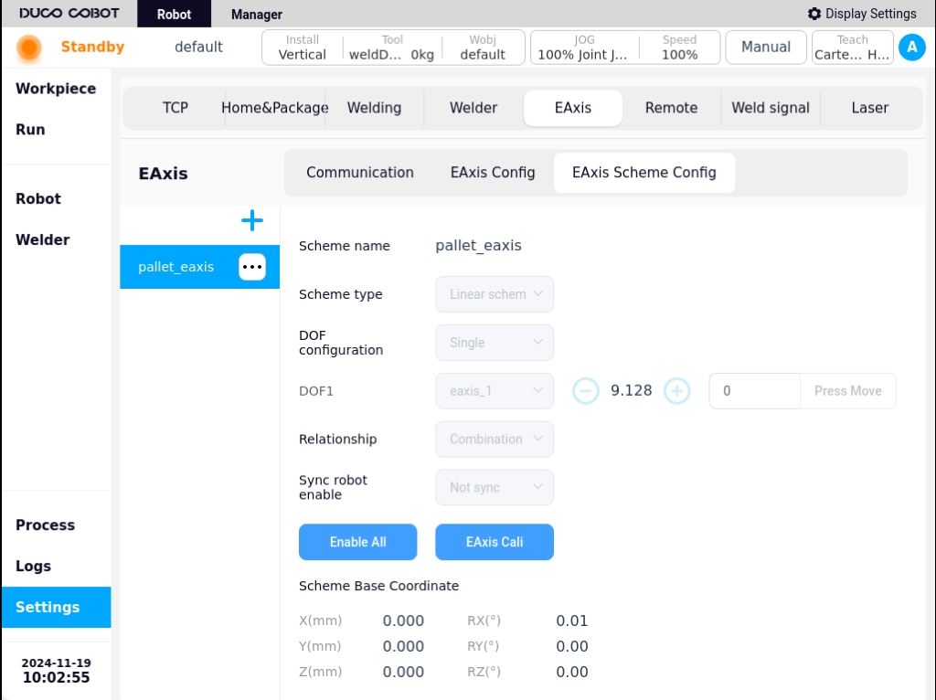
3. Program configuration#
The Program Configuration page allows you to create a new external axis program, as well as edit or delete an existing external axis program. On the left side of the page is the external axis scheme navigation tab, on the right side of the page is the external axis scheme parameter content corresponding to the external axis scheme tab, as well as all enable/disable buttons, external axis calibration, external axis tap buttons. On the right side of the page are the parameters of the external axis scheme corresponding to the external axis scheme tabs, as well as the buttons for All Enable/Disable, External Axis Calibration, External Axis Tap, and you can manually input the target position of the external axis, and so on. You can also enter the target position of the external axis manually by long-pressing the “Press and hold to move” button to move it to the manually entered target position.
Clicking on the  icon in the upper right corner of the left section of the page will bring up the virtual keyboard as follows:
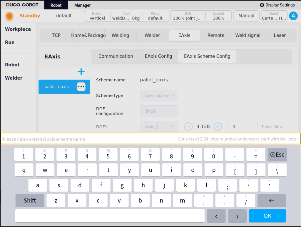
After entering the name of the newly created external axis scheme, e.g. “scheme_test” is displayed as shown in the figure below, the left navigation tab area will display the name of the newly created external axis scheme “scheme_test”, and the color of the font is red, which means that the scheme is invalid, i.e. it is a scheme without configured external axis scheme parameters. If the font color is red, it means that the external axis scheme is invalid, i.e., it is a scheme that has not been configured with external axis scheme parameters. Only when the font color is black, it means the external axis scheme is valid. The content area on the right side displays the content that needs to be configured for this new external axis scheme. The parameters that can be configured are: scheme type, degree of freedom configuration, axis-robot relationship, and synchronized robot enable.

Parameter description:
Type of program: Linear guide program or indexing machine program;
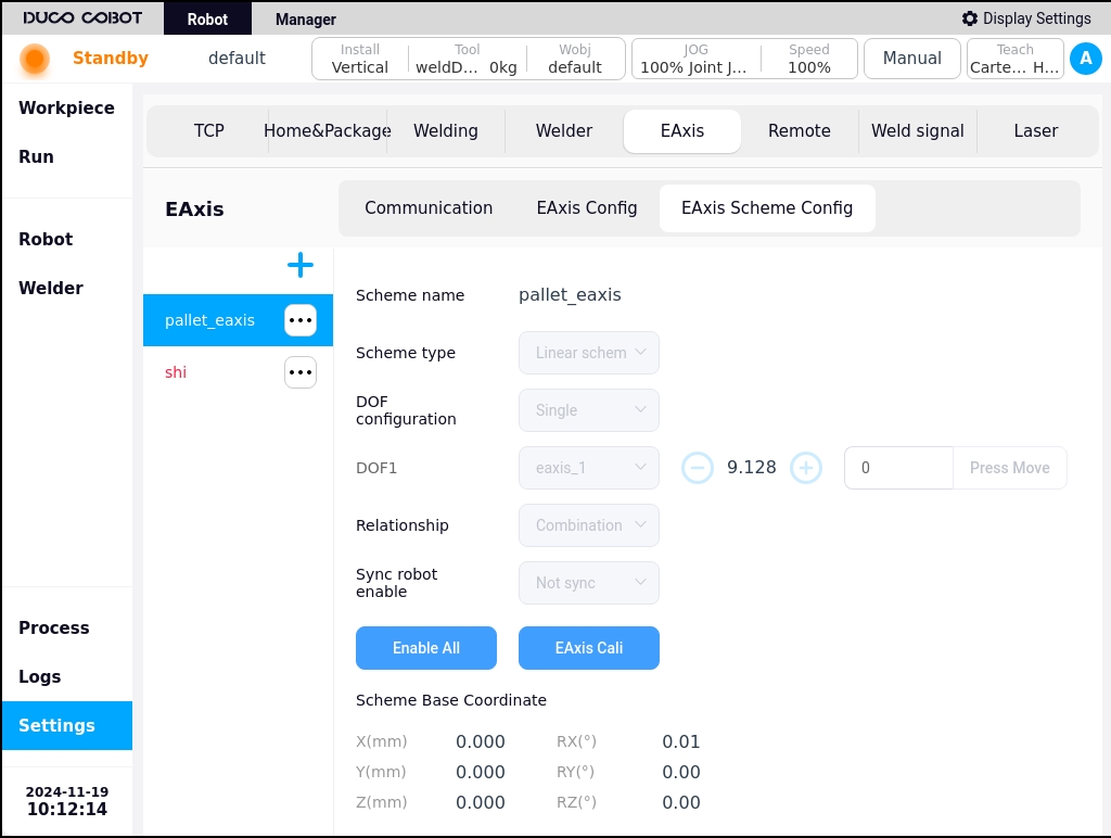
Degree of Freedom Configuration: The linear guide program currently supports only single degree of freedom, and the variator program supports single degree of freedom and two degrees of freedom. After selecting the degree of freedom, you can bind the degree of freedom to the external axis according to the number of degrees of freedom selected. As shown in the figure below, the single degree of freedom linear guide program degrees of freedom 1 bound linear guide external axis eaxis_3;
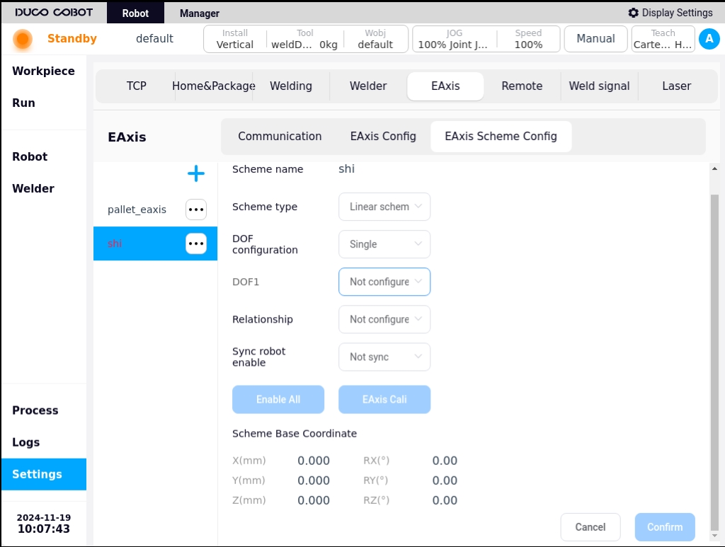
Axis-robot relationship: independent or combined, i.e., the external axis is independent of the robot or the robot is fixed to the external axis;
Note
Note: Axis-robot combinations only support single-degree-of-freedom external axis.
Synchronized Robot Enable: The default is not synchronized, if configured as “Synchronized”, the external axis scheme will synchronize the enable/disable operation after the robot completes the enable/disable;
Schematic base coordinate system: describes the position of the external axis base coordinate system in the world coordinate system, which by default coincides with the world coordinate system, and which is calibrated by the external axis calibration process.
After configuring the above configurable parameters, as shown in the figure below, you can click the “OK” button at the bottom right corner of the page to complete the configuration of the external axis scheme.

In the external axis scheme editing state, the “Enable All” or “Disable All” and “External Axis Calibration” buttons on the page are disabled, and the external axis tap operation buttons are inoperable. The External Axis Push buttons cannot be operated; External axis program enable/disable operations and external axis calibration are only available when the external axis program is not edited. The external axis tap buttons can only be operated when the external axis scheme is enabled, i.e. all external axes are enabled for tap operation.
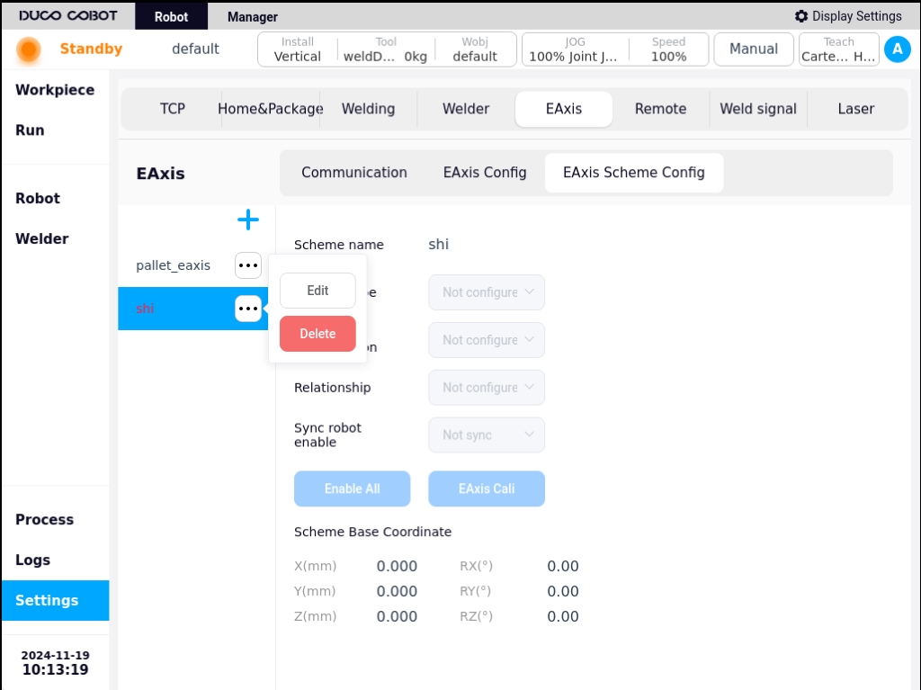
Clicking on the  icon after the external axis scheme name on the left side of the page will bring up a popup box that displays “Edit” and “Delete” buttons, allowing you to edit or delete the selected external axis scheme.
4. External axis calibration#
The external axis calibration process is used to calibrate the base coordinate system of the external axis scheme. In the non-editing state of the external axis program, click the “External Axis Calibration” button on the page to enter the external axis calibration process page. According to the different types of external axes, the external axis calibration is divided into two types: linear guide calibration and indexer calibration.
Linear guide calibration#
Depending on the type of relationship between the axes and the robot, there are two types of linear guideway calibration: combined and independent. The external axis program “scheme_test” is used as an example to introduce the calibration process of the combined linear guide program.
Click the “External Axis Calibration” button on the page as shown below:
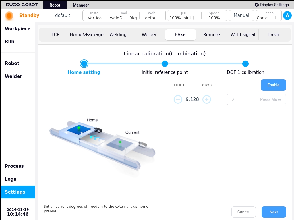
Determine the zero point: You can press and hold the icons on the left and right sides of the external axis position display to move the external axis, determine the zero point position of the external axis, and then click the “Next” button;
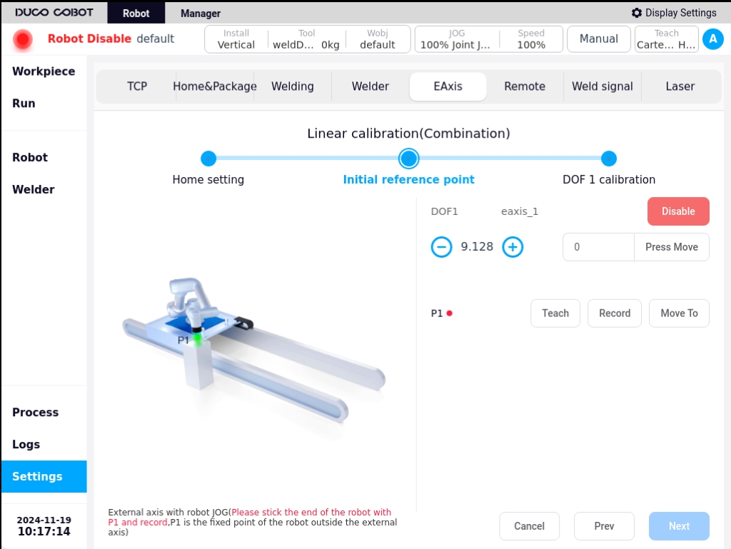
Initial reference point: P1 point is a fixed point outside the robot and the external axis, respectively JOG external axis and the robot, so that the robot end and P1 point paste and record; teach the robot or external axis position, P1 point after the display from | A5 | | A6 | click on the “Next” button;
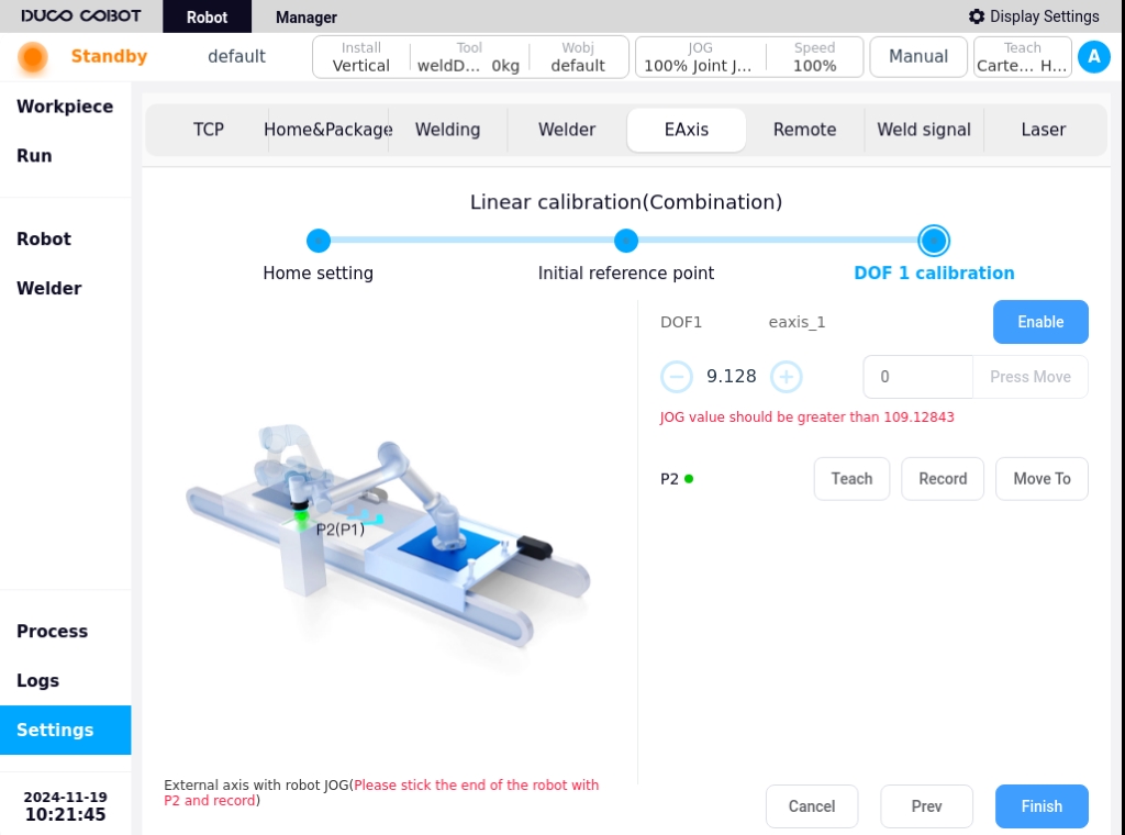
Degree of freedom 1 calibration: Similarly, JOG the external axis with the robot, so that the end of the robot and the P2 point (in the physical environment, that is, the original P1 point) affixed to the record; demonstration of teaching and record the robot end position points, click “Finish”.

Shifter Calibration#
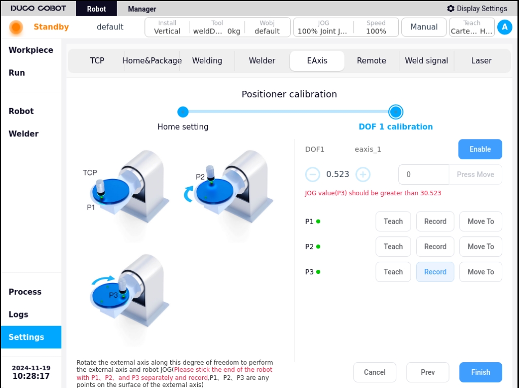
When the external axis type is a shifter, the external axis calibration is the shifter calibration. Here we take the external axis solution of single-degree-of-freedom indexer type as an example to introduce the calibration process of the indexer solution. Click on the “External Axis Calibration” button on the page as shown below:
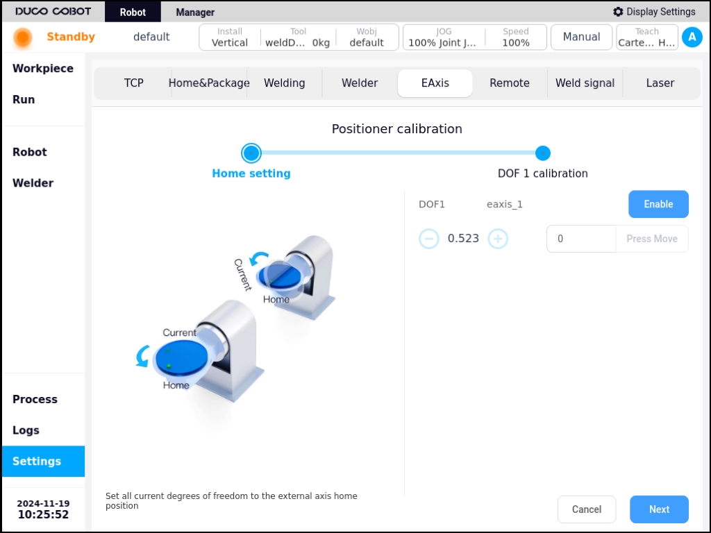
Determine the zero point: You can press and hold the icons on the left and right sides of the external axis position display to move the external axis, determine the zero point position of the external axis, and then click the “Next” button;
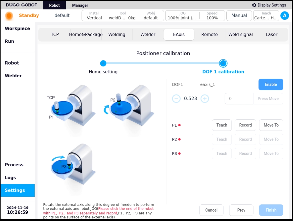
Degree of freedom 1 calibration: P1, P2, P3 are any point on the surface of the external axis, JOG external axis and the robot, so that the end of the robot and the P1, P2, P3 points were affixed to the merger record; demonstration of teaching and recording of the robot’s end position points, click on the “Finish” can be.
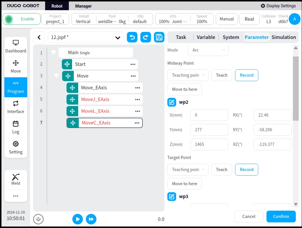
5. External axis programming function block#
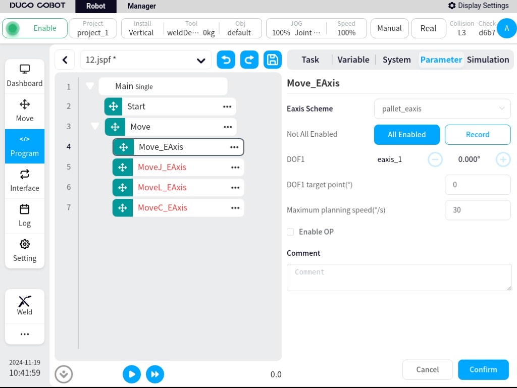
There are four function blocks related to external axes: Move_Eaxis, MoveJ_Eaxis, MoveL_Eaxis, and MoveC_Eaxis.
Move_Eaxis
Command block for separate movement of external axes. Parameters can be set:
External Axis Program: name of the target external axis program.
Degree of Freedom Target Point: The position of the degree of freedom corresponding to the target external axis scheme, the recorded position degree of freedom and unit change according to the degree of freedom set by the external axis scheme and the type of external axis scheme, the unit is ° or mm.
Maximum planning speed: Maximum planning speed of the external axes, changed according to the type of the corresponding external axis program, in °/s or mm/s.
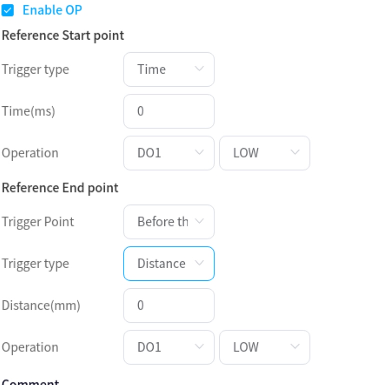
Enable OP: The OP function allows you to set the general-purpose digital output port status or operate customized events during trace execution.
If OP is enabled, the following configuration is required:
Can be triggered after the start of the trajectory and before/after the end of the trajectory
Trigger type: can choose no trigger, time trigger, distance trigger
Trigger delay: Setting time, unit ms
Trigger distance: set the distance, unit mm
Trigger action: select the port and port status, or operate a customized event

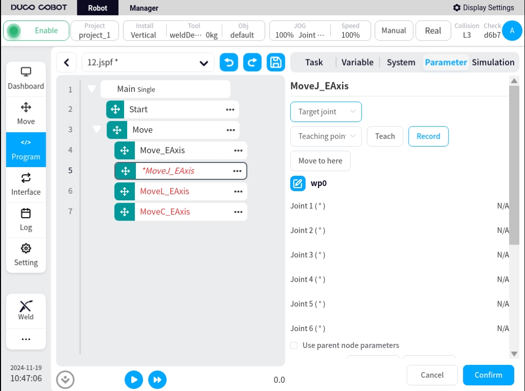
MoveJ_Eaxis
External axis and robot joint motion. The robot moves according to the joint motion and can choose to move to a target joint or a target pose. Parameters can be set:
Target position: can be set by way of demonstration or set as a variable, which can be changed manually after the demonstration is set.
Use parent node coordinate system: can be set when selecting the target position attitude, when checked, this function block uses the reference coordinate system set by the parent node Move function block, checked by default.
Reference coordinate system: can be set when selecting the target position attitude, when the parent node coordinate system is unchecked, the reference coordinate system can be set separately for this function block.
Use parent node parameters: when checked, this function block uses the parameters of joint angular velocity and joint angular acceleration set by the parent node Move function block; when unchecked, you need to set the joint angular velocity and joint angular acceleration for this function block individually, checked by default.
Joint angular velocity: unit °/s, can be entered directly or by selecting the variable.
Joint angular acceleration: unit °/s2, can be entered directly or by selecting the variable.
Fusion radius: unit mm0 means no fusion.
Enable OP: The OP function allows you to set the general-purpose digital output port status or operate customized events during trace execution.
The configuration of the external axis parameters is the same as Move_EAxis and will not be repeated here.
If OP is enabled, the following configuration is required:
Can be triggered after the start of the trajectory and before/after the end of the trajectory
Trigger type: can choose no trigger, time trigger, distance trigger
Trigger delay: Setting time, unit ms
Trigger action: select the port and port status, or operate a customized event
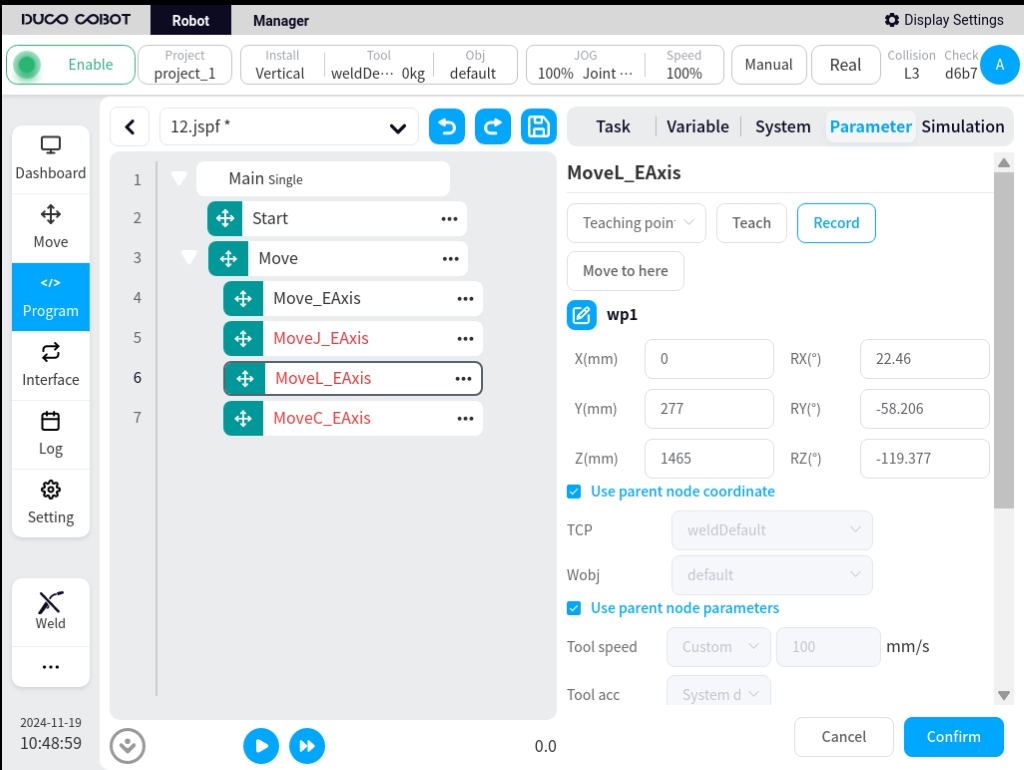
MoveL_Eaxis
The external axis moves in a straight line with the robot. The robot moves in a straight line to the target attitude, which can be parameterized:
Target attitude: can be set by way of demonstration or set as a variable, which can be changed manually after the demonstration is set.
Use parent node coordinate system: when checked, this function block uses the reference coordinate system set by the parent node Move function block, checked by default.
Reference coordinate system: when the Use parent node coordinate system is unchecked, you can set the reference coordinate system for the function block separately.
Use parent node parameters: when checked, the function block uses the end velocity and end acceleration parameters set by the parent node Move function block; when unchecked, you need to set the end velocity and end acceleration for the function block individually, default is checked.
End speed: unit mm/s, can be entered directly or by selecting a variable.
End acceleration: unit mm/s2, can be entered directly or by selecting a variable.
Fusion radius: unit mm, 0 means no fusion
Enable OP: The OP function allows you to set the general-purpose digital output port status or operate customized events during trace execution.
OP parameter configuration is the same as Move_EAxis.
The configuration of the external axis parameters is the same as Move_EAxis and will not be repeated here.
MoveC_Eaxis
External axis with robot circular motion. The robot moves according to an arc or a full circle, which can be parameterized:
Pattern: Arc or full circle
Midpoint Attitude/Midpoint 1: Can be set by way of demonstration or set as a variable, which can be changed manually after the demonstration is set.
Target Attitude/Midpoint 2: Can be set by demonstration or set as a variable, which can be changed manually after the demonstration is set.
Use parent node coordinate system: when checked, this function block uses the reference coordinate system set by the parent node Move function block, checked by default.
Reference coordinate system: when the Use parent node coordinate system is unchecked, you can set the reference coordinate system for the function block separately.
Use parent node parameters: when checked, the function block uses the end velocity and end acceleration parameters set by the parent node Move function block; when unchecked, you need to set the end velocity and end acceleration for the function block individually, default is checked.
End speed: unit mm/s, can be entered directly or by selecting a variable.
End acceleration: unit mm/s2, can be entered directly or by selecting a variable.
Fusion radius: unit mm, 0 means no fusion
Attitude control mode: If “consistent with the end point” is selected, the robot’s attitude is planned according to the end point attitude for the attitude in the circular arc path; if “consistent with the starting point” is selected, the robot’s attitude is planned according to the starting point attitude for the attitude in the circular arc path, and the attitude during the path is consistent with the starting point; if “constrained by the center of the circle” is selected, the robot’s attitude is constrained by the attitude change relative to the circular arc motion. If “consistent with start point” is selected, the robot’s pose is planned according to the start point pose, and the pose during the path is consistent with the start point; if “constrained by center of circle” is selected, the robot’s pose is constrained by the change of the pose with respect to the movement of the circular arc.
Enable OP: The OP function allows you to set the general-purpose digital output port status or operate customized events during trace execution.
OP parameter configuration is the same as Move_EAxis.
The configuration of the external axis parameters is the same as Move_EAxis and will not be repeated here.