Welding execution#
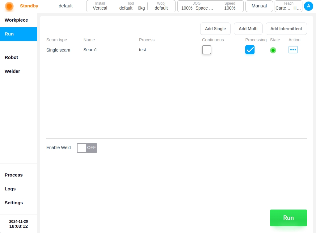
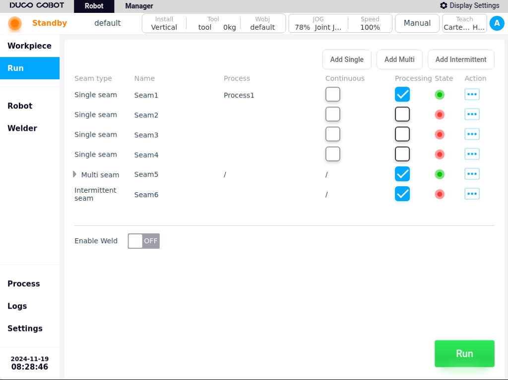
Click “Run” in the navigation bar to enter the Weld Execution page, as shown below.
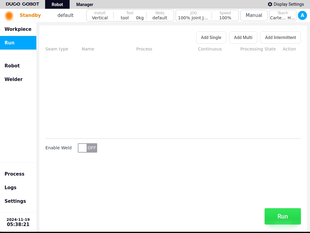
The Weld Execution page is mainly used for adding weld seams, creating weld tasks, displaying the list of weld tasks, and fine-tuning some of the weld parameters during the weld execution process.
You can add a single weld, a multi-layer weld and an intermittent weld by using the different buttons in the upper right corner of the page.
Single pass weld#
Click the “Add Single Weld” button in the upper right corner of the page to bring up the virtual keyboard, which displays the weld name “Weld x” by default, as shown in the figure below.
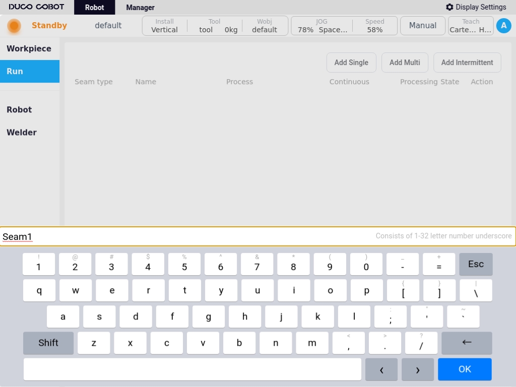
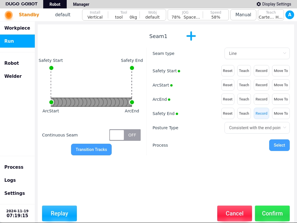
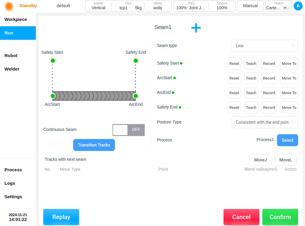
Users can also customize the weld name. After confirming the weld name, such as “Weld 1”, click the “OK” button on the keyboard to enter the single weld definition page, as shown in the figure below. As shown in the figure below.
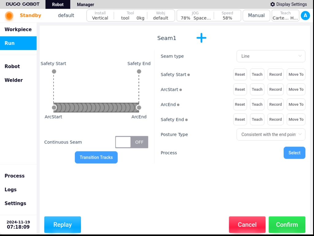
Welding seam type: Four options are available: straight line, arc, full circle, and multi-point mode;
Starting Safety Point: The safe position from the arc start point before starting to weld;
Arc Start Point: Position of arc ignition prior to the start of welding;
Arc closing point: The position where the arc is extinguished after finishing the weld;
End Safety Point: The safe position from the arc closing point after finishing the weld;
Attitude constraints: Used to set the attitude relationship between the torch and the weld seam. Unconstrained: Executed according to the torch attitude during the demonstration; Consistent with the starting point attitude: During the welding process, the torch maintains the attitude at the starting point; Constrained by the center of the circle: The torch attitude remains unchanged with respect to the circle arc
Process: The name of the process file used is displayed, and clicking the “Select” button after it opens the single-pass process file selection dialog box, where you can select the process file used for the weld;
Continuous Weld: Configure whether the weld is continuous or not; when it is continuous, the current weld is continuous with the next section of the weld without restarting the arc, and the closing point of the current weld is the starting point of the next weld; When it is not continuous, the next weld needs to restart the arc, and the current weld trajectory point has an arc closing point and an end safety point.
To teach a point, click the “Teach Point” button after the corresponding point to jump to the robot control page. In the robot control page, teach the robot to determine the point of use, and then jump back to the current weld editing page after teaching is completed and recorded. Users can also teach the point directly through the teach pendant, click the corresponding point and click “Record current point”. Click the button of “Record Current Point” to finish the teaching record. Press and hold the “Move to this point” button to move the robot to this point. Click “Reset” button to clear the value of the point, and the point status light will be restored to gray. When the points are taught sequentially, the corresponding point status light will change from gray to green as shown in the following figure.
Click the “Select” button after the process, the pop-up single-pass process file selection dialog box is shown in the figure below.
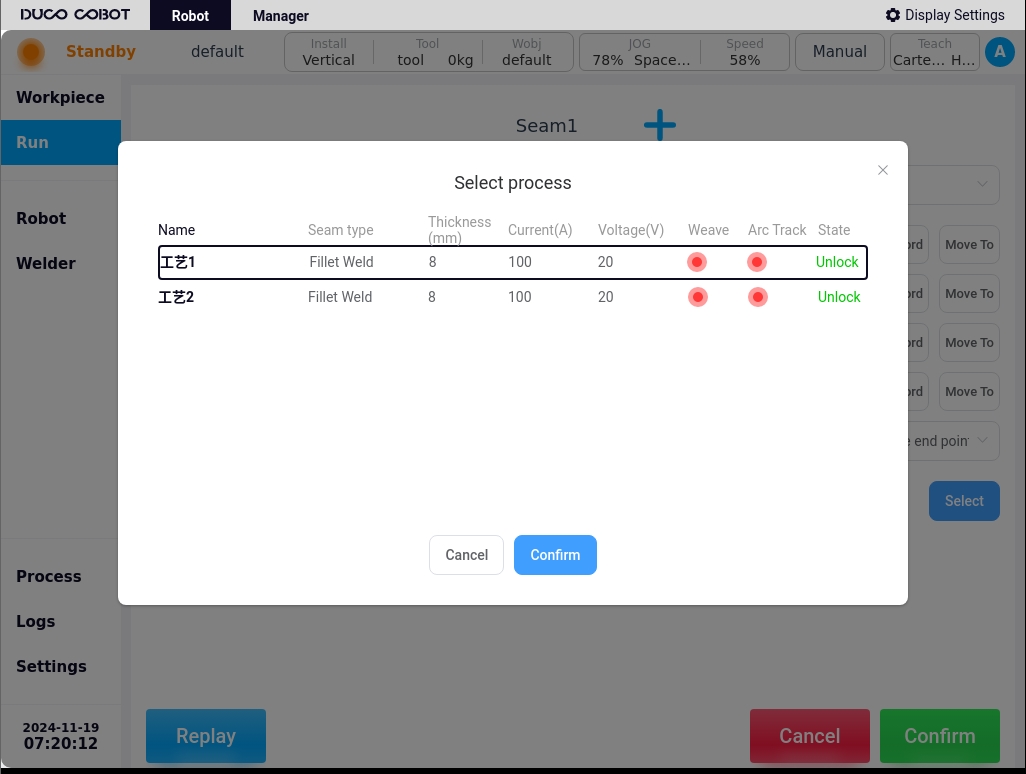
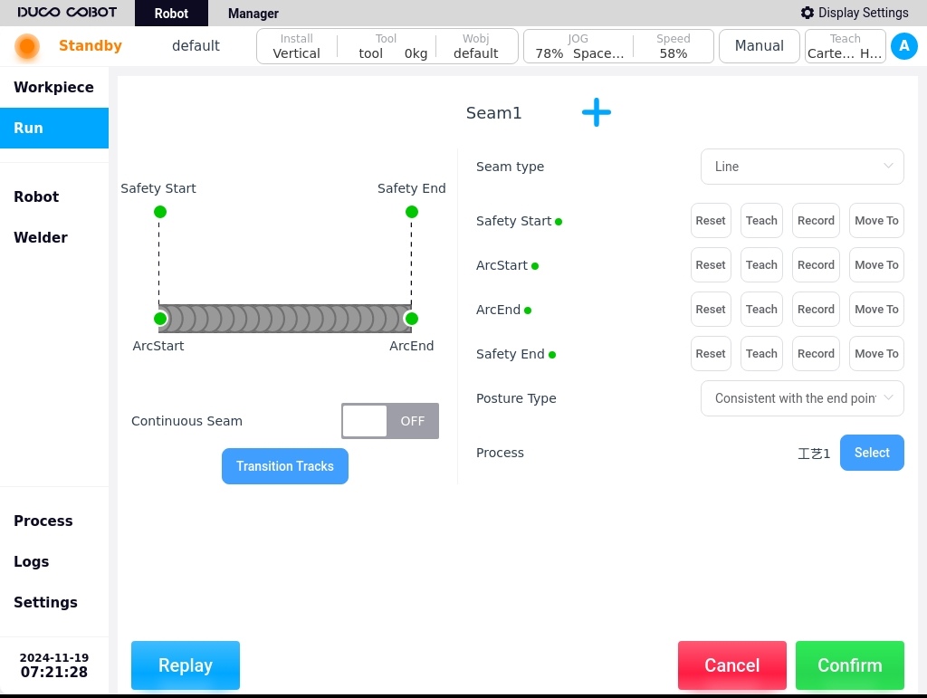
Select the required process file, such as selecting the “process 1”, click “OK” button, select the process dialog box disappears, the weld editing page after the process is displayed in the following chart.
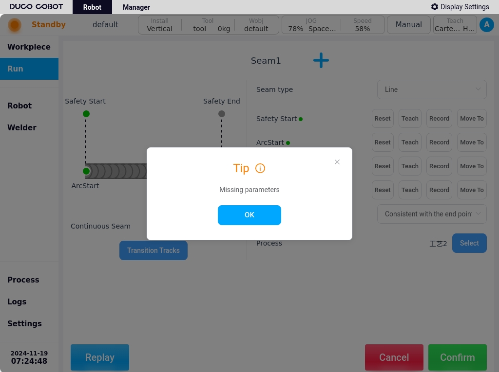
Users can click the “Repeat” button at the bottom left corner of the page, and the robot will run according to the taught points. When the point record is incomplete or the process file is not selected, click the “Repeat” button to pop up a prompt dialog box, as shown in the figure below. As shown in the figure below.
Select the type of weld, in order to teach the beginning of the safety point, the starting point, the closing point and the end of the safety point, configure the attitude constraints and whether the continuous weld, as well as selecting a good process file, and then click the “OK” button on the right corner of the page to save the weld configuration information. Click the “OK” button in the lower right corner of the page to save the seam configuration information, OK will add a weld to the task list of the workpiece, as shown in the figure below. If you want to abandon the current changes Click the “Cancel” button to exit to the welding execution page.
Users can also add a weld by clicking on the  icon on the current weld editing page, and the weld name will be generated as “Weld x” by default.
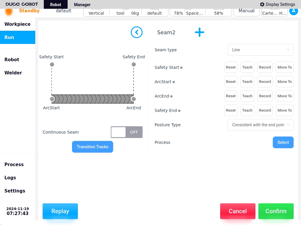
For example, if you click the add icon on the “Weld 1” editing page, you will enter the “Weld 2” editing page, as shown in the figure below.
icon on the current weld editing page, and the weld name will be generated as “Weld x” by default.
For example, if you click the add icon on the “Weld 1” editing page, you will enter the “Weld 2” editing page, as shown in the figure below.
Similarly, after configuring the weld configuration information, click the “OK” button to save the weld configuration information and add it to the list of weld tasks for the current workpiece to return to the weld execution page.
Users can add multiple weld tasks sequentially through the icon, and switch to different welds to edit the corresponding weld information through the  and
and  icons.
After editing the weld configuration information, click the “Confirm” button to return to the weld execution page.
icons.
After editing the weld configuration information, click the “Confirm” button to return to the weld execution page.
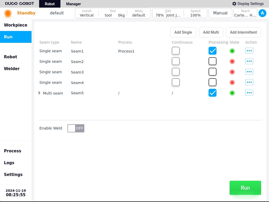
For example, in the “Weld 2” editing page, click the Add icon twice in a row to add “Weld 3” and “Weld 4”, and finally click the “Confirm” button to return to the welding execution page as shown below. Finally, click the “Confirm” button to return to the weld execution page, as shown in the figure below.
Multi-layer, multi-pass welds#
Click the “Add Multi-Layer Multi-Pass Weld” button at the top right corner of the page to bring up the virtual keyboard, which displays the weld name “Weld x” by default. Users can also customize the weld name. After confirming the weld name, such as “Weld 5”, click the “OK” button to enter the multi-layer multi-pass weld definition page, as shown in the figure below.

Basic Configuration Information#
Welding seam type: Options are straight line, arc, full circle, and composite trajectory;
Bevel Type: Options are Natural, Single V, V-Shape, Steep Edge Bevel, U-Bevel, Single Steep Edge Bevel, J-Bevel;
Sub-pass deviation datum: Weld coordinate system offset datum, optionally relative to the root pass, relative to the previous pass;
Click the “Root Path Definition” button to enter the Root Path Definition page, as shown below.
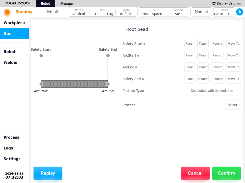
When the type of weld seam is straight line, arc or circle, the configuration information required for the definition of the root weld path is the same as that for the corresponding type of single-pass weld seam, and will not be repeated here.
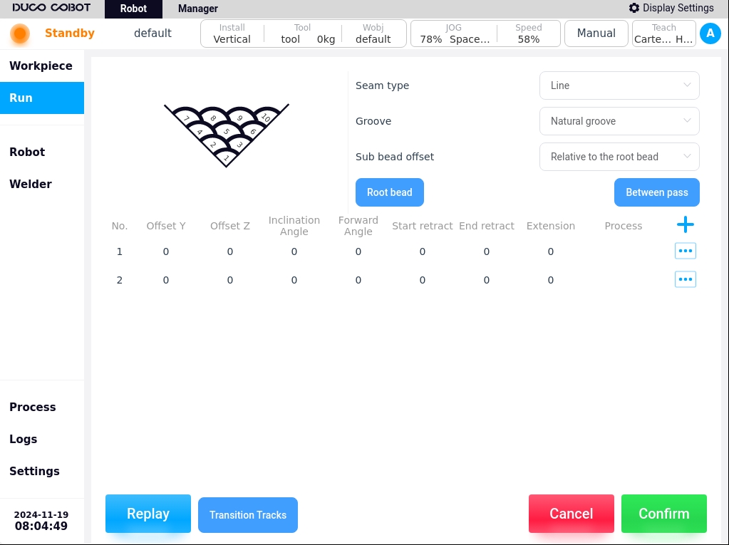
When the weld type is Composite Trajectory and the Type default is Linear + Linear, the Root Weld Path Trajectory Definition page is shown below.
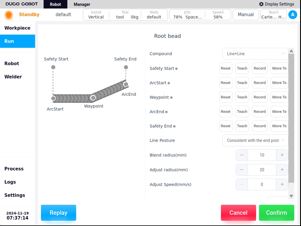
Among the points to be modeled in the Root Weld Path Definition page are the Start Safety Point, Start Arc Point, Excess Point, Finish Arc Point, and End Safety Point. The configured parameters are: straight line segment attitude constraint, fusion radius and process. The composite trajectory types are straight line + straight line, straight line + arc, straight line + arc + straight line, arc + straight line + arc, totaling four types.
When the composite trajectory is selected as straight line + arc, the points that need to be taught in the definition page of the root weld path trajectory are the start safety point, arc start point, excess point, intermediate point, arc closing point and end safety point. Configuration parameters relative to the straight line + straight line composite trajectory also need to configure the arc segment attitude constraints, adjustment radius, that is: straight line segment attitude constraints, arc segment attitude constraints, fusion radius, adjustment radius and process.
When the composite trajectory is selected as straight line + arc + straight line, the points that need to be taught in the definition page of the trajectory of the root weld channel are the starting safety point, starting arc point, over point, intermediate point, over point, closing arc point, and ending safety point. The configuration parameters are the same as those required for Straight Line + Circular Arc.
When the composite trajectory is arc + straight line + arc, the points to be shown on the root weld path trajectory definition page are the start safety point, arc start point, intermediate point, excessive point, excessive point, intermediate point, arc closing point, and end safety point. The configuration parameters are the same as those required for straight line + arc.
Note
Note: Composite trajectory transitions are rounded by default.
Click the icon in the upper right corner of the current multi-layer multi-pass weld list to add a weld, e.g., add a weld number 2 as shown in the following figure.

The weld pass list mainly displays the weld pass number, Y offset, Z offset, tilt angle, push/pull angle, start indent, end indent, dry elongation, process name, and the weld pass operation icon.
Click on the weld pass operation icon  and the popup window will be displayed as follows.
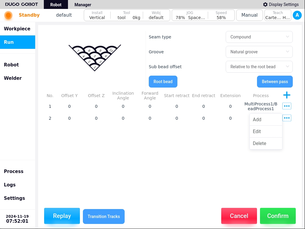
New: Clicking the “New” button will add a new single weld path after the currently selected path;
Note
Note: Clicking on the serial number 1 channel operation icon only adds new functions.
Edit: Click the “Edit” button to enter the weld channel edit page, you can edit the above information mainly displayed in the weld channel list;
Delete: Clicking “Delete” will bring up a confirmation dialog box, after confirmation, you can delete the welding channel.
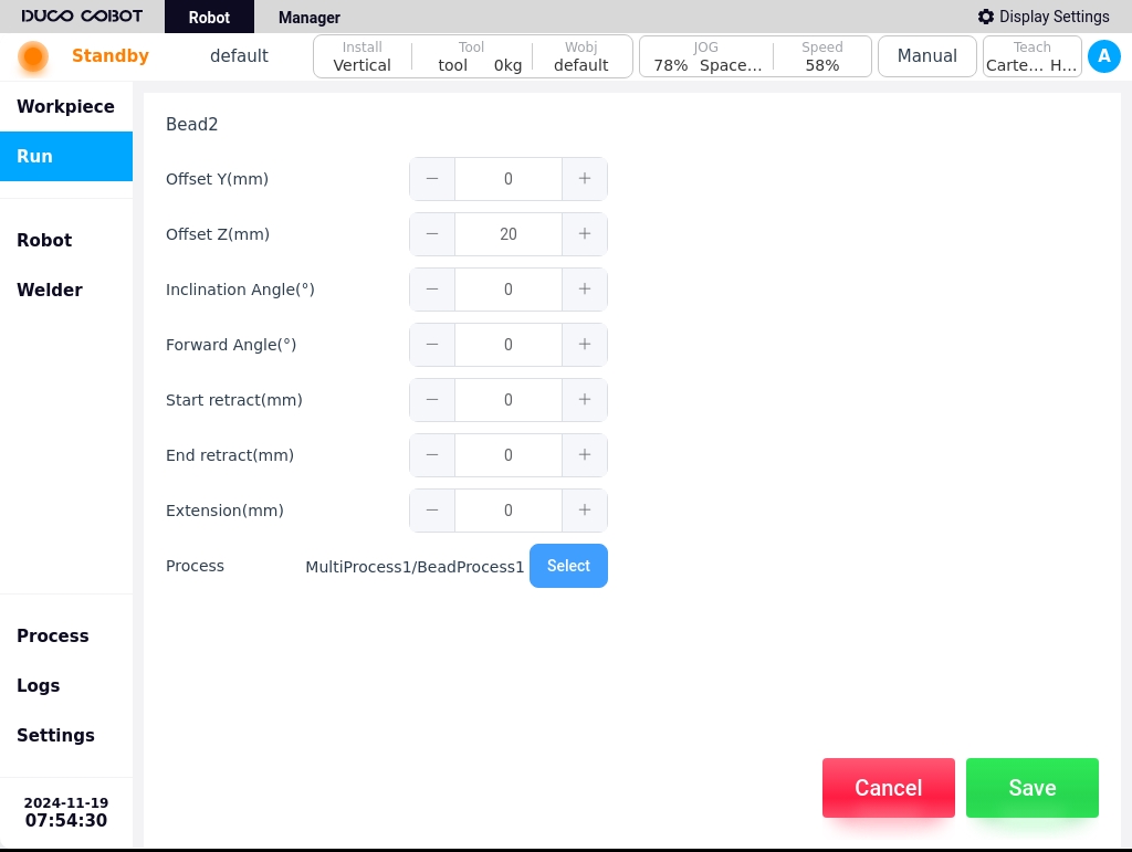
For example, click the “Edit” button in the pop-up window of the weld channel 2 operation icon to enter the weld channel 2 edit page, as shown in the following figure.
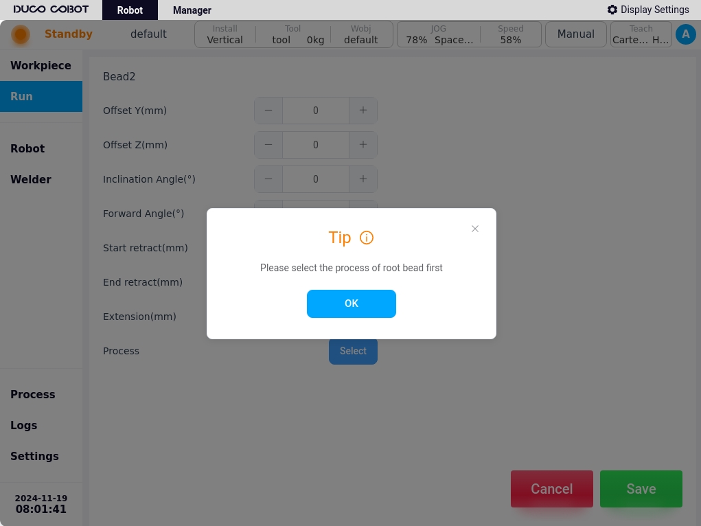
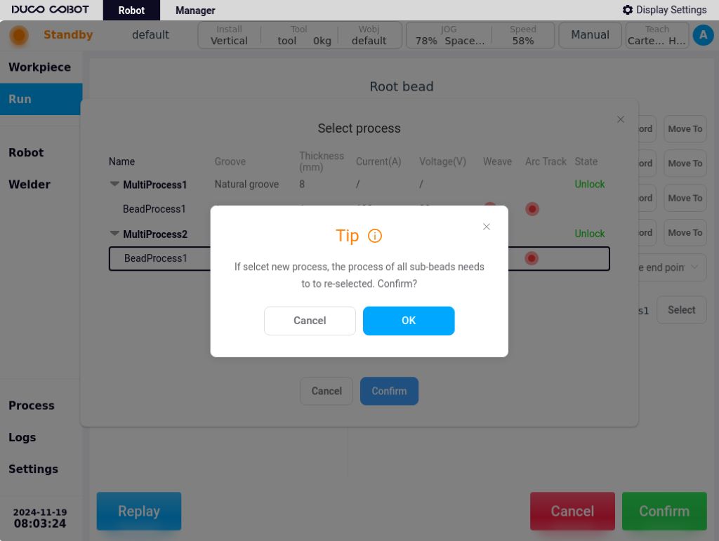
When selecting a process, the Multilayer Multi-Pass Process File dialog box opens, and the process for the root weld pass must be selected first, otherwise a pop-up window will prompt the user as shown below.
The process selected for a sub-pass can only select a single pass process from the process group selected for the root pass. If you want to change the process group, you need to select another process group in the root channel. A pop-up window will appear as shown below.
After confirmation, users can select other groups of process files, such as selecting “Multi-layer multi-channel process 2 / weld channel process 1”, the selection is confirmed and will be cleared of other weld channel selected process files, as shown in the figure below.As shown in the figure below.
After configuring the weld channel information, click the “Confirm” button to return to the weld execution page, as shown in the following figure.
Weld channel definition#
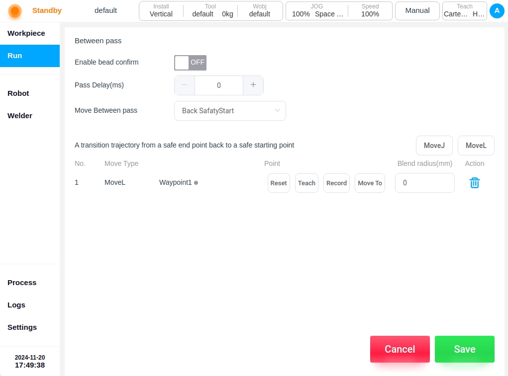
For multi-layer, multi-pass welds, you can configure the definition of the passes, by clicking on the “Define Passes” button, you will enter the passes definition page. The following options can be configured:
Enable weld channel confirmation:
If Enable is selected, each time a weld is completed, a popup confirmation or a button confirmation is required to proceed to the next weld. Please configure the confirmation method in Basic Settings/Welding Signal.
Weld Path Delay:
Without enabling the weld pass confirmation, you can set the weld pass delay time so that after completing the operation of one weld, you can delay the operation of the next weld for a certain period of time.
Movement between weld channels:
You can choose between “Return to safe point” and “Reciprocating motion”, with “Return to safe point” as the default. If “Return to safe point” is selected, after each weld is completed, the robot will return to the safe starting point for the next weld. If “Reciprocate” is selected, after each weld is completed, the robot will work in the opposite direction of the previous weld.
If you select “Return to safe point”. By default, the robot moves from the safe end point to the safe start point in a straight line, which in some cases may be unreachable or collision problem. You can add a transition point and select the way to move to the transition point (straight line/joint). As shown in the picture:
Note
The speed at which the robot runs in the transition trajectory is defined in the process file
Note
When reciprocating motion is selected, the position offset is based on the direction of travel of the root weld channel.
Intermittent weld#
Click the “Add Intermittent Weld” button at the top right corner of the page to bring up the virtual keyboard, which displays the weld name “Weld x” by default. Users can also customize the weld name. After confirming the weld name, such as “Weld 6”, click the “OK” button to enter the intermittent weld definition page, as shown in the figure below.
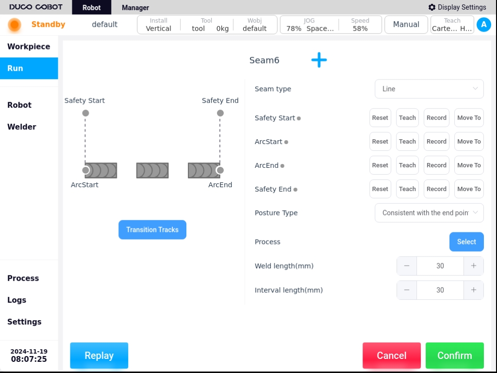
The configuration information required for an interrupted seam definition is similar to that of a single-pass seam definition and will not be repeated here. The difference is that there is no continuous seam parameter configuration for interrupted seams.
In addition, the intermittent weld needs to be configured with two parameters: weld length and interval length. After configuring the weld channel information, click the “Confirm” button to return to the welding execution page, as shown in the figure below.
Transition track#
When there are multiple weld tasks in the Weld Task List, and you return to the safe end point after executing a job, by default the robot will move to the safe start point of the next job weld by joint movement. In some cases, the robot cannot move safely due to the presence of an obstacle, for example. You can add transition points at the end of each weld. Select how the robot moves to the transition point (linear/articulated).
The transition trajectory of a single weld page is defined as follows
The transition trajectory of a multi-layer, multi-pass weld page is defined as follows
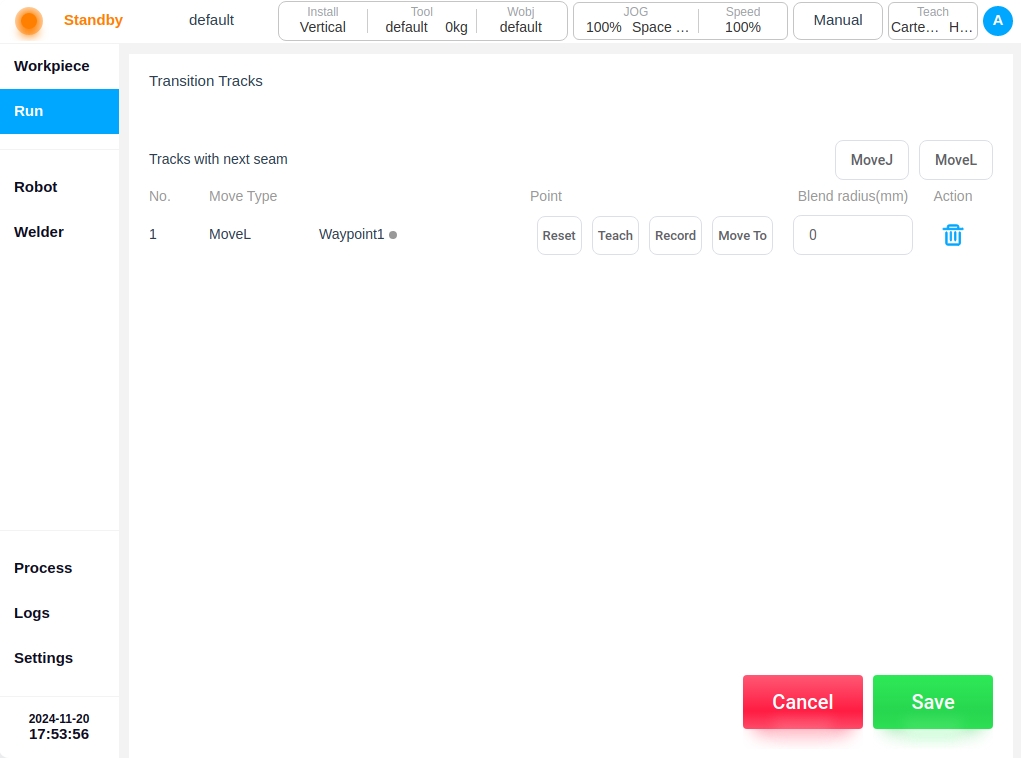
Note
The speed at which the robot runs in the transition trajectory is defined in the process file
Welding tasks#
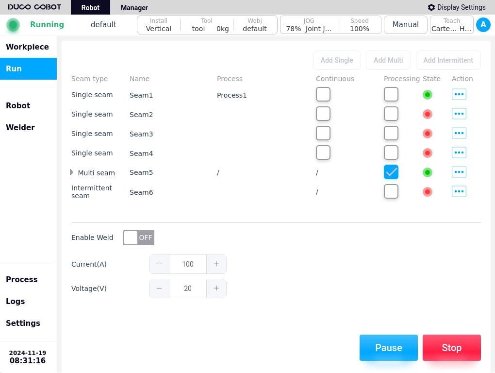
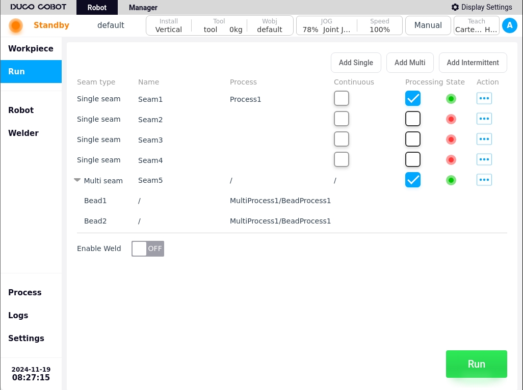
The Weld Job List displays a list of all welds in the current workpiece, in the order they were added. Each weld displays information including type, weld name, process file,
The information displayed for each weld includes the type, weld name, process file, whether the weld is continuous with the next one, whether it is processed, status, and the weld task operation icon. Processing is checked by default, and consecutive weld passes can only be checked or unchecked at the same time;
The status bar for completed weld configuration shows a green status light, and the status bar for incomplete weld configuration shows a red status light. Click on any weld in the current workpiece welding task list on the Weld Execution page.icon , the popup window will be displayed as follows.
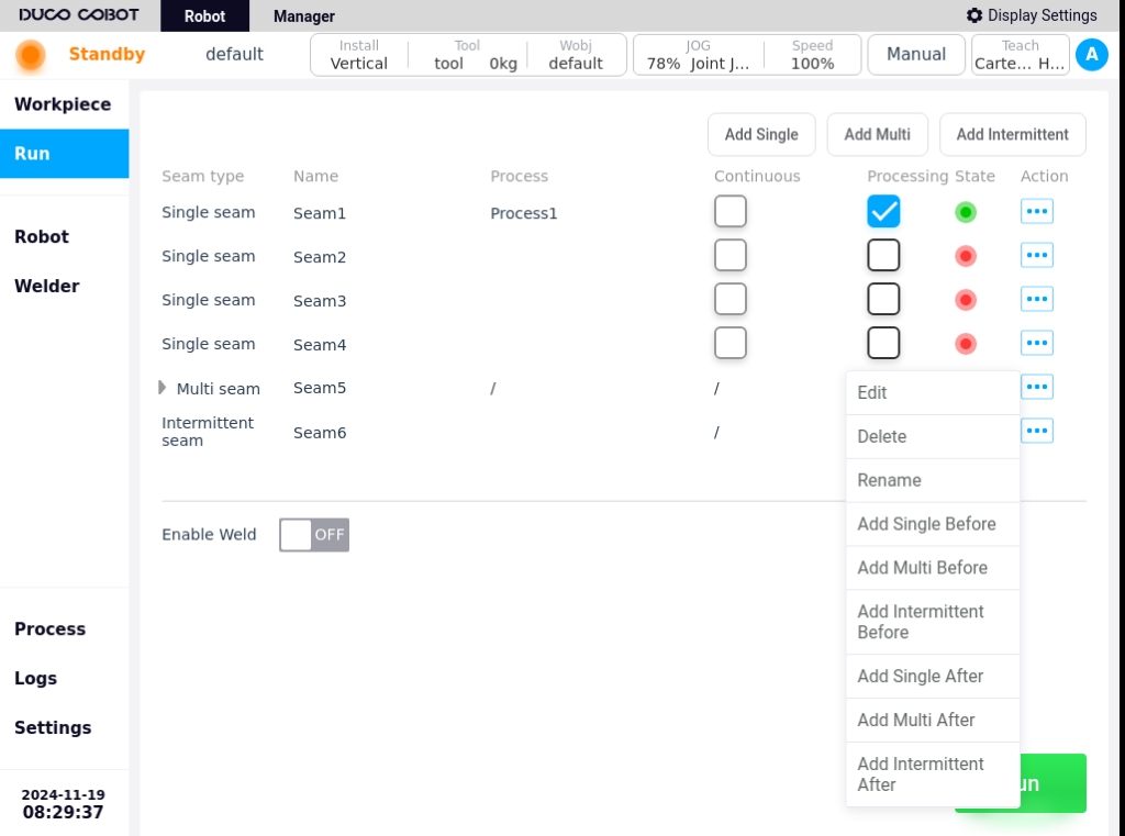
Edit: Click “Edit” to enter the editing page of the selected weld task, and you can edit the configuration information of the weld.
Delete: Clicking “Delete” will bring up a confirmation dialog box, and the task can be deleted after confirmation.
Note
Note: If the deleted weld has a continuous weld relationship with the front and back weld, a dialog box will pop up indicating that there is an associated weld, and you will need to re-determine the position of the front and back weld after deletion.
Rename: Click “Rename” button, the keyboard will pop up, enter the new name of the weld, OK can be modified.
Adding single weld: Click “Add single weld” button, the keyboard will pop up, confirm the name of the weld, and then enter the editing page of the new single weld.
After confirming the weld configuration information, you can add a single weld task before the current weld task.
Adding multiple welds forward: Click “Add Multiple Welds Forward” button, the keyboard will pop up, confirm the weld name, and then enter the Add Multiple Welds task editing page, and confirm the weld name.
After confirming the weld configuration information, you can add a multi-layer multi-pass weld task before the current task.
Add Intermittent Seam: Click “Add Intermittent Seam” button, the keyboard will pop up, confirm the seam name, and then enter the Add Intermittent Seam page.
After confirming the weld configuration information, you can add a new intermittent weld task before the current weld task.
Add single weld backward: Click “Add single weld backward” button, the keyboard will pop up, confirm the name of the weld, and enter the Add single weld task edit page.
After confirming the weld configuration information, you can add a new one-pass weld task after the current weld task.
Adding multiple welds backward: Click “Add multiple welds backward” button, the keyboard will pop up, confirm the name of the weld, and enter the Add Multiple Welds task editing page.
After confirming the weld configuration information, you can add a multi-layer multi-pass weld task after the current one.
Add Intermittent Seam: Click “Add Intermittent Seam” button, the keyboard will pop up, confirm the seam name, and then enter the Add Intermittent Seam page.
After confirming the weld configuration information, you can add a new intermittent weld task after the current weld task.
After checking the weld to be processed, click the “Start” button at the bottom right corner of the weld execution page to start executing the weld task. If there are any unfinished configurations for the selected weld, a pop-up window will be displayed as shown below.
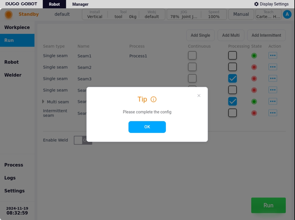
After confirming and configuring the weld seams that are checked for processing, the welding task can only be executed when the status bar of all checked weld seams shows a green status light.
Welding Mode When this parameter is enabled, the arc will start to weld, and when it is not enabled, it will weld with an empty running track. If you need to fine-tune some parameters during execution, you need to turn on the welding online fine-tuning switch. You can turn on the “Enable online fine-tuning” switch in the “Basic Settings–Welding Settings” page. When running a weld, the parameters that can be adjusted are weld current, weld voltage. If you enable the Pendulum setting, you can also adjust the pendulum amplitude, pendulum frequency, and dwell time on both sides, as shown in the following figure.