


Welder connection#
The current version supports welding types including gas-shielded welding, argon arc welding, laser welding; different welding types support different types of welders and communications, as follows:
Welding power supply can choose digital communication and analog communication, according to the actual needs of the choice
digital communication#
When using CAN communication, you need to refer to the Collaborative Robot User’s Manual (Hardware Section), and the welder’s manual, and interface the CAN communication ports of both. A 120Ω termination resistor has been connected inside the CAN port of the robot control cabinet. There is no need to connect a separate resistor. Take the example of Aotai NBC-500RP Plus / NBC-350RL series welding machine:
Check the Collaborative Robot User’s Manual (Hardware Section) to find the CAN communication interface, as shown below:

From the table, it is clear that CAN communication uses pins 11, 18, and 20.
Check the manual of the welder and find the CAN communication interface on the welder side, as shown in the following figure:
3. Connect the welder communication cable #2 to the corresponding line to the robot expansion interface pin 18, as described in the robot and welder manual. Connect line 7 to pin 20 of the Robot Expansion Interface. Connect the No. 3/6 pin-to-pin line to the robot expansion interface pin 11 to complete the wiring.
analog communication#
Wiring Instructions
When connecting the Multi-Collaborative Robot to the welding power source for analog communication, two sets of relays are required, and the number of relay sets is selected according to the function actually used. The specific wiring method differs according to the type of port of the welding power source. The details are as follows:
When the welding power port type is PNP, the wiring is as follows.

When the welding power port type is NPN, the wiring is as follows.

Welding machine power supply given welding current and welding voltage into the robot controller 0-10V analog voltage output interface (AO interface)
The actual current and voltage returned by the welder’s power supply are connected to the robot controller’s analog voltage input interface (AI interface).
The robot-side IO correspondence table is as follows
Terminal Name |
Port Name |
Access Explanation |
|---|---|---|
DIO |
DI1 (Port 5) |
Arc start success signal |
DI2 (Connector 7) |
Preparation Signal |
|
DI3 (Port 9) |
Successful seek signal |
|
DO1 (Port 6) |
Arc Start Signal |
|
DO2 (Connector 8) |
Wire Feed Signal |
|
DO3 (Connector 10) |
Filament Return Signal |
|
DO4 (Connector 12) |
Gas Detection Signal |
|
DO5 (Interface 14) |
Robot Ready |
|
DO6 (Interface 16) |
Seek Enable |
|
DO7 (Connector 18) |
JOB1 signal |
|
DO8 (Connector 20) |
JOB2 signal |
|
CIO |
DO9 (Interface 6) |
JOB3 signal |
EIO |
AI1 (Interface 1) |
Welding Current |
AI2 (Port 3) |
Welding Voltage |
|
AO1 (Connector 5) |
Given Current |
|
AO2 (Port 7) |
Given Voltage |
Software operation#
Configure the communication mode of the welding machine, the specific operation is as follows: Click on the welding equipment to enter the welding type selection page, the welding type includes gas shielded welding, argon arc welding, laser welding; select the current welding machine type, click OK to enter the welding equipment configuration page;

Select “Digital Communication” for the communication mode, and click the “Connect” button in the lower right corner to take effect.
Welder adaptation (gas welding):
The current version of the welder models that support digital communication are:
Welder Manufacturers |
Welder Models |
Communication Protocol |
|---|---|---|
AUTO TAI |
NBC-500RP Plus / NBC-350RL |
CAN |
General Heavy Duty |
RB_P Series |
CAN |
MEGMEET |
DeviceNet/CAN |
|
Wiltek |
DeviceNet |
|
OTC |
DeviceNet |
|
EWM |
DeviceNet |
|
Panasonic |
DeviceNet |
|
WECO |
Modbus TCP |
|
Must be high |
CAN |
|
Kemppi |
Modbus TCP |
|
Spirex |
Modbus TCP |
|
Vogner |
DeviceNet |
|
CLOOS |
DeviceNet |
Caution
When Configuring MEGMEET, Add Welding Machine Parameter Settings:
1.For Artsen series welding machines: N00 SiA, N01 2, N02 1, N05 OFF, N06 ON, N10 ON, P05 ON, P02 DF/DN;
2.For Dex2 series welding machines: N03 2, N05 ON, N10 SiA;
Adaptation of welding machines (TIG welding):
The welder models that support digital communication in the current version are:
Welding Machine Manufacturer |
Welding Machine Model |
Communication Protocol |
|---|---|---|
Aotai |
WSM-400R / WSM-315 |
CAN |
Hezong |
WSM-400 |
CAN |
Shanghai General |
WSM-400T-pro |
DeviceNet/CAN |
EWM |
Tetrix |
DeviceNet |
Welder adaptation (laser welding):
The welder models that support digital communication in the current version are:
Welding Machine Manufacturer |
Welding Machine Model |
Communication Protocol |
|---|---|---|
DUCO |
Standard |
Modbus TCP |
Select “Analog Communication” for the communication mode, and click the “Connect” button in the lower right corner to take effect.
Analog communication (gas welding):
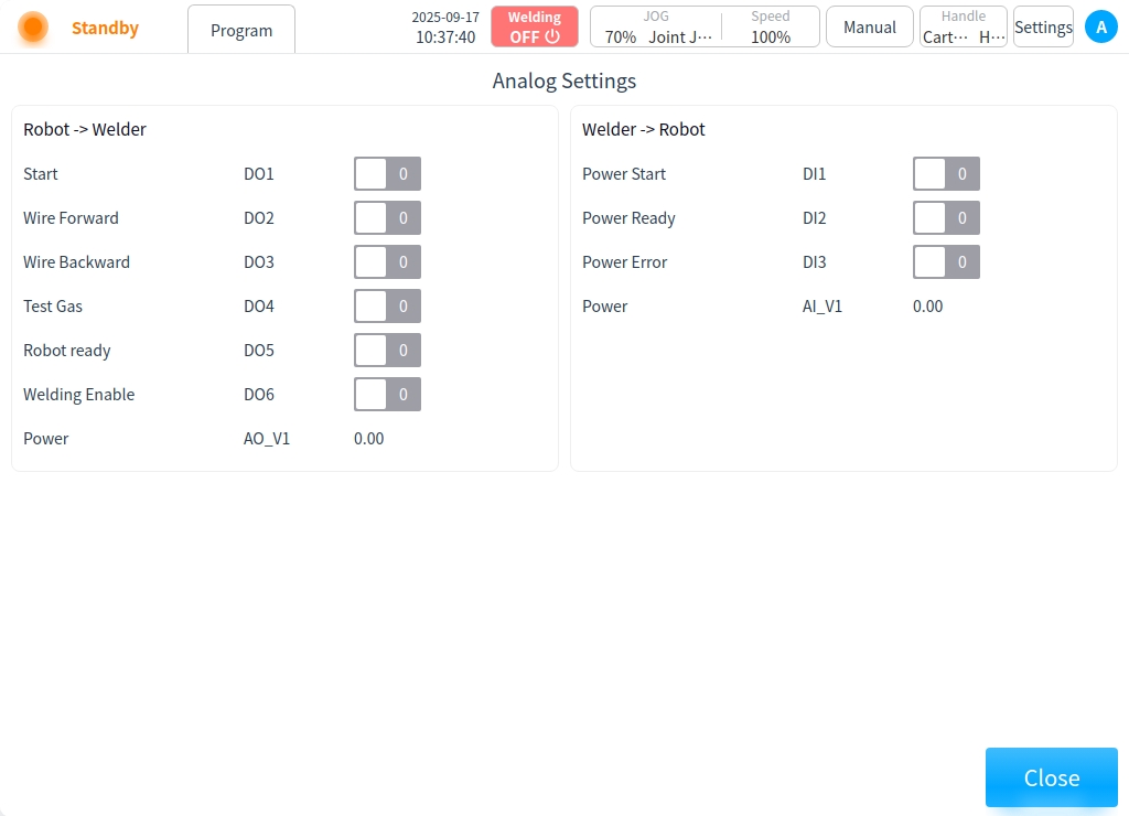
Click “IO Correspondence Table” to enter the IO Correspondence Table page, you can check the IO signal correspondence and status.

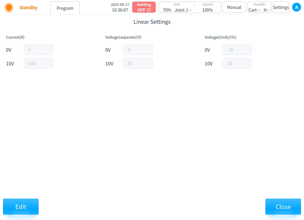
Click on the “Linearization” setting and click on the “Edit” button to set the correspondence between welding current and voltage and analog quantity.

Analog communication (TIG welding):
Click “IO Correspondence Table” to enter the IO Correspondence Table page, you can check the IO signal correspondence and status.

Click on the “Linearization” setting and click on the “Edit” button to set the correspondence between welding current and voltage and analog quantity.
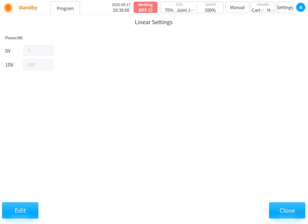
Analog communication (laser welding):
Click “IO Correspondence Table” to enter the IO Correspondence Table page, you can check the IO signal correspondence and status.
Click on the “Linearization” setting and click on the “Edit” button to set the correspondence between welding current and voltage and analog quantity.
When the setting is completed, the analog communication setting is finished. Welding operations can be executed in the welding process package, and information such as process parameters can be set directly in the process library.